Downloaded 649 times
![The solution will be
V= Vm 1 ( )
V= V (1‐ cos2πf t)
m n
Where fn =
Expression For RRRV(Rate Of Rise Of Restriking
Voltage)
V= Vm 1 ( )
V
RRRV = =
RRRV will be maximum when
=1
or t=
Hence, maximum value of RRRV
[
RRRVmax =
V
]
Further the peak of restriking voltage occurs when v is maximum i.e., when
= 0
or = 0 = sinπ
t √LC](https://image.slidesharecdn.com/circuitbreakerarcphenomena-130322210416-phpapp01/75/Circuit-breaker-arc-phenomena-10-2048.jpg)


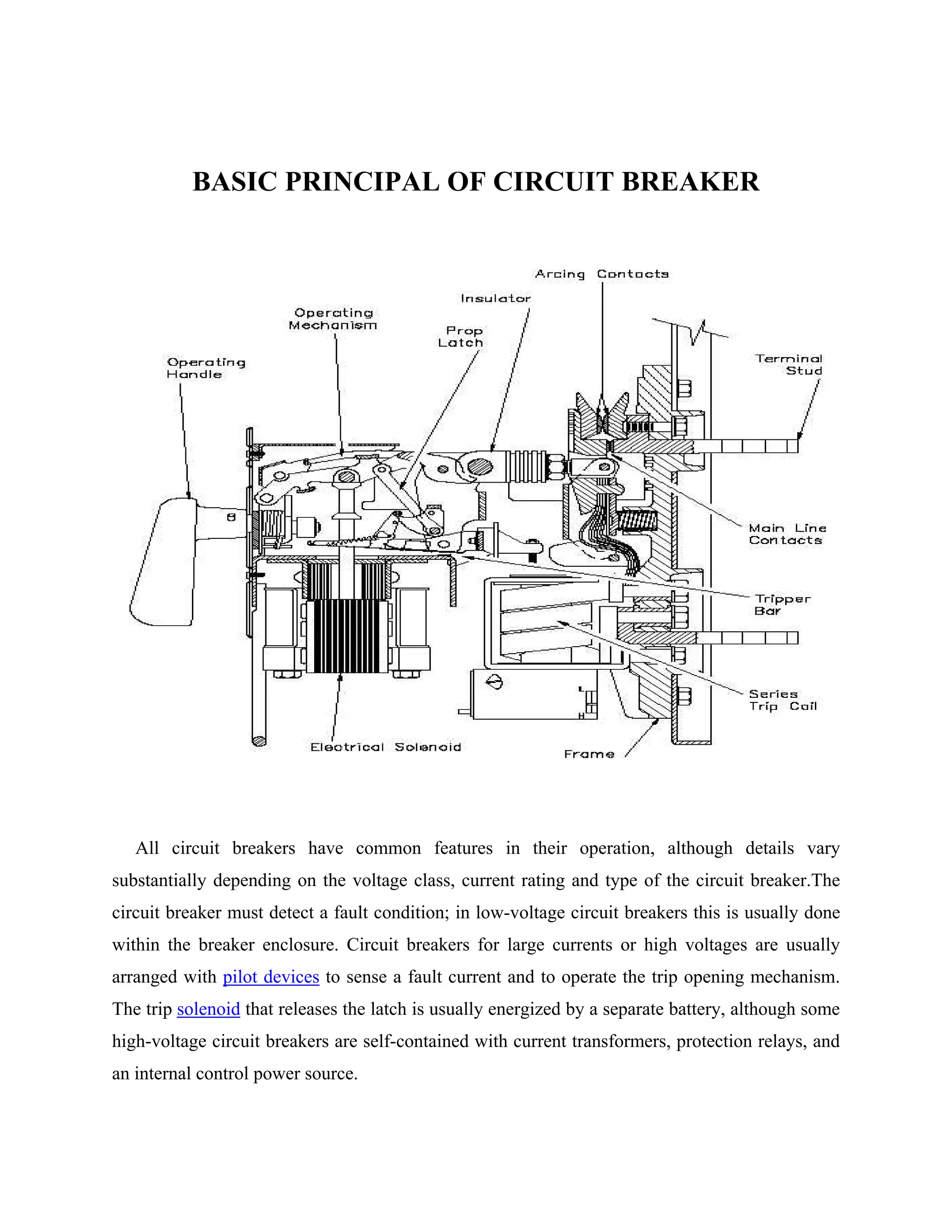
A circuit breaker is a device used to protect electrical circuits from damage caused by short circuits or overloads. It functions by automatically opening a circuit when excess current is detected. When a fault occurs, the circuit breaker detects it and uses stored mechanical energy to separate its contacts, interrupting the current. This creates an electric arc that must be contained and extinguished in a controlled way before the contacts can be re-closed to restore power. Common circuit breaker components detect faults, open contacts, extinguish arcs through techniques like lengthening or splitting it, and reclose contacts once faults have cleared.


