This document discusses separately excited DC motor drives fed by single-phase and three-phase converters. It describes the basic circuit of a single-phase separately excited DC motor drive using a semi-converter or full-converter. Equations for back EMF, average back EMF, developed torque, and average developed torque are provided. Operation is analyzed for both continuous and discontinuous armature current. Three-phase fully controlled converter fed drives are also introduced. Four-quadrant operation, time ratio control, and current limit control methods are summarized.
Closed Loop Speed Control of a BLDC Motor Drive Using Adaptive Fuzzy Tuned PI...IJERA Editor
Brushless DC Motors are widely used for many industrial applications because of their high efficiency, high
torque and low volume. This paper proposed an improved Adaptive Fuzzy PI controller to control the speed of
BLDC motor. This paper provides an overview of different tuning methods of PID Controller applied to control
the speed of the transfer function model of the BLDC motor drive and then to the mathematical model of the
BLDC motor drive. It is difficult to tune the parameters and get satisfied control characteristics by using normal
conventional PI controller. The experimental results verify that Adaptive Fuzzy PI controller has better control
performance than the conventional PI controller. The modeling, control and simulation of the BLDC motor have
been done using the MATLAB/SIMULINK software. Also, the dynamic characteristics of the BLDC motor (i.e.
speed and torque) as well as currents and voltages of the inverter components are observed by using the
developed model.
Experimental Investigations of the Self-Controlled Synchronous Motor Connecte...IJPEDS-IAES
This paper concerns the experimental investigations of the three-phase line
commutated SCR inverter fed synchronous motor. The fabricated system
consists of a line-commuted inverter, a three-phase synchronous motor with
the excitation winding connected in series to the inverter input, a terminal
voltage sensor and a gate-pulse generating circuit. The firing pulses for SCRs
of the inverter are generated by the microprocessor in proper sequence with
the help of synchronizing signal derived from the terminal voltages of the
synchronous machine. The steady state performance characteristics are
obtained experimentally using the fabricated system. The experimental
results show that a three-phase synchronous motor supplied by a line
commutated inverter with the excitation winding connected in series to the dc
link provide excellent characteristics of the conventional dc series motor.
A survey on Single Phase to Three Phase Cyclo-Converter fed Induction MotorIJSRD
In various application of electrical energy especially in in industrial areas there are two type of current, Direct Current and Alternating Current are used. Generally fixed voltage, constant frequency Single-Phase or Three-Phase AC is easily available, yet for different applications various types of magnitudes and/or frequencies are essential. This paper presents a survey on 1-̉ۢ to 3-̉ۢ cycloconverter technique using thyristor with 3-̉ۢ induction motor along load frequency analysis. The cycloconverter is inspected in its utmost straight forward form without further output filters or elaborate control technique.
Fuzzy logic Control & Minimizing Commutation Torque Ripple for Brushless DC M...Editor IJMTER
Brushless dc motor still suffers from commutation torque ripple, which mainly depends
on speed and transient line current in the commutation interval. This paper presents a novel circuit
topology and a dc link voltage control strategy to keep incoming and outgoing phase currents
changing at the same rate during commutation. A dc–dc single-ended primary inductor converter
(SEPIC) and a switch selection circuit are employed in front of the inverter. The desired
commutation voltage is accomplished by the SEPIC converter. The dc link voltage control strategy is
carried out by the switch selection circuit to separate two procedures, adjusting the SEPIC converter
and regulating speed. The cause of commutation ripple is analyzed, and the way to obtain the desired
dc link voltage is introduced in detail. Finally, simulation and experimental results show that,
compared with the dc–dc converter, the proposed method can obtain the desired voltage much faster
and minimize commutation torque ripple more efficiently at both high and low speeds and the closed
loop control is achieved by Fuzzy logic control.
Development of a Novel Three Phase Grid-Tied Multilevel Inverter TopologyIAES-IJPEDS
The conventional line-commutated ac-to-dc converters/ inverters have square-shaped line current. It contains higher-order harmonics which generates EMI and it causes more heating of the core of distribution or power transformers. PWM based inverters using MOSFET/IGBT have higher switching losses, and the power handling capability and reliability are quite low in comparison to thyristors/ SCR. A thyristor based forced commutated inverters are not suitable for PWM applications due to the problems of commutation circuits. A pure sinusoidal voltage output or waveform with low harmonic contents is most desirable for ac load using dc to ac conversion. This paper presents a new multilevel inverter topology in which three phase ac- to-dc converter circuits are used in inversion mode by controlling the switching angle. Due to natural commutation, no separate circuit is required for synchronization. In this paper simulation and analysis are done for grid-tied three-phase 6-pulse, Two three-phase, 3-pulse and 12-pulse converter. These converters are analysed for different battery voltage and different switching angle combinations in order to reduce the total harmonic distortion (THD). Three-phase harmonic filters are further added to the grid side to reduce the harmonic content in the line current. A comparative study of these converters is also presented in this paper.
USE OF ARNO CONVERTER AND MOTOR-GENERATOR SET TO CONVERT A SINGLE-PHASE AC SU...IAEME Publication
This method is used to control the speed of a three-phase induction motor by using a three-phase to three-phase cycloconverter from a single-phase supply and to compare the use of ARNO converter and motor-generator set to convert a single-phase supply to a three-phase supply. ARNO converter is a rotating device which convert single-phase AC to three-phase AC. The three-phase supply needed for the three-phase induction motors which used in blowers, exhausters an oil pumps. A motor-generator set is a device for converting electrical power to another form. They are used to convert frequency, voltage or phase of power. Thus, both ARNO converter and motor-generator set have been used here one at a time to convert a single-phase AC supply to three-phase AC. Both have their own advantages and disadvantages
IJRET : International Journal of Research in Engineering and Technology is an international peer reviewed, online journal published by eSAT Publishing House for the enhancement of research in various disciplines of Engineering and Technology. The aim and scope of the journal is to provide an academic medium and an important reference for the advancement and dissemination of research results that support high-level learning, teaching and research in the fields of Engineering and Technology. We bring together Scientists, Academician, Field Engineers, Scholars and Students of related fields of Engineering and Technology.
International Journal of Engineering Research and Applications (IJERA) is an open access online peer reviewed international journal that publishes research and review articles in the fields of Computer Science, Neural Networks, Electrical Engineering, Software Engineering, Information Technology, Mechanical Engineering, Chemical Engineering, Plastic Engineering, Food Technology, Textile Engineering, Nano Technology & science, Power Electronics, Electronics & Communication Engineering, Computational mathematics, Image processing, Civil Engineering, Structural Engineering, Environmental Engineering, VLSI Testing & Low Power VLSI Design etc.
Simulation of 3-phase matrix converter using space vector modulationIJECEIAES
This paper illustrates the simulation of 3-phase matrix converter using Space Vector Modulation (SVM). Variable AC output voltage engendered using matrix converter with bidirectional power switches controlled by appropriate switching pulse. The conventional PWM converter engenders switching common mode voltage across the load system terminals, which cause to common mode current and its leads to bearing failure in load drive. These problems can be rectified using SVM and which minimize the effect on the harmonic fluctuation in AC output voltage and stress on the power switch is reduced using bidirectional switch for proposed 3-phase matrix converter. The simulation results have been presented to validate the proposed system using matlab / simulink.
Performance of Six-Pulse Line-Commutated Converter in DC Motor Drive ApplicationZunAib Ali
This paper presents the speed control of DC motor using six pulse controlled rectifier. The
conventional Proportional Integral (PI) control is used for firing angle control. The armature current is fed
back and compared with reference current representing desired speed values. The proposed system is
simulated using SimPowerSystem and Control System Matlab toolbox. The time domain plot of reference
and actual armature current are shown in results section. The results are satisfactory with deleterious effect
on input current. The frequency plot of input current is provided to show the harmonic contents, generated
as a result of control operation.
A Soft Switching Control Strategy Based On Interleaved Boost Converter for BL...IAES-IJPEDS
In this paper, Zero-Voltage-Transition (ZVT) based two-cell interleaved
boost Power Factor Correction (PFC) converter for permanent magnet
brushless DC motor (PMBLDCM) drive has been proposed.For achieving
soft switching, only one switch is used in auxiliary circuit which reduces the
torque ripple and switching losses. In this proposed control strategy, the DC
link voltage is which is proportional to the desired speed of the BLDC motor
controlled with interleaved boost converter. In this paper, six switch and four
switch VSI is implemented with interleaved boost converter topology. A
comparison is made between the six switch and four switch VSI fed
PMBLDC Motor drive and torque Analysis as been done. To validate the
proposed work, simulation study is presented. The results showed that
proposed converter control strategy operating under soft switching mode
improves the efficiency in wide range of the speed control.
A Novel Control Strategy of Indirect Matrix Converter Using Space Vector Modu...IJPEDS-IAES
This paper introduces a control scheme of Indirect Matrix Converter which includes space vector modulation to stabilize the frequency variations. The terminal voltage and frequency of any synchronous machine can be controlled easily with this scheme. Further the control strategy is proposed and implemented in Matlab/Simulink Embedded system which gives significant better performance compared to conventional control technique like better Total Harmonic Distortion (THD), more output voltage with same Modulation Index, less switching stress and less switching loss. This method might prove effective for wind energy conversion system using DFIG as the DFIG speed is close to synchronous speed. The complete control strategy is verified using MATLAB/Simulink.
Computer Science
Active and Programmable Networks
Active safety systems
Ad Hoc & Sensor Network
Ad hoc networks for pervasive communications
Adaptive, autonomic and context-aware computing
Advance Computing technology and their application
Advanced Computing Architectures and New Programming Models
Advanced control and measurement
Aeronautical Engineering,
Agent-based middleware
Alert applications
Automotive, marine and aero-space control and all other control applications
Autonomic and self-managing middleware
Autonomous vehicle
Biochemistry
Bioinformatics
BioTechnology(Chemistry, Mathematics, Statistics, Geology)
Broadband and intelligent networks
Broadband wireless technologies
CAD/CAM/CAT/CIM
Call admission and flow/congestion control
Capacity planning and dimensioning
Changing Access to Patient Information
Channel capacity modelling and analysis
Civil Engineering,
Cloud Computing and Applications
Collaborative applications
Communication application
Communication architectures for pervasive computing
Communication systems
Computational intelligence
Computer and microprocessor-based control
Computer Architecture and Embedded Systems
Computer Business
Computer Sciences and Applications
Computer Vision
Computer-based information systems in health care
Computing Ethics
Computing Practices & Applications
Congestion and/or Flow Control
Content Distribution
Context-awareness and middleware
Creativity in Internet management and retailing
Cross-layer design and Physical layer based issue
Cryptography
Data Base Management
Data fusion
Data Mining
Data retrieval
Data Storage Management
Decision analysis methods
Decision making
Digital Economy and Digital Divide
Digital signal processing theory
Distributed Sensor Networks
Drives automation
Drug Design,
Drug Development
DSP implementation
E-Business
E-Commerce
E-Government
Electronic transceiver device for Retail Marketing Industries
Electronics Engineering,
Embeded Computer System
Emerging advances in business and its applications
Emerging signal processing areas
Enabling technologies for pervasive systems
Energy-efficient and green pervasive computing
Environmental Engineering,
Estimation and identification techniques
Evaluation techniques for middleware solutions
Event-based, publish/subscribe, and message-oriented middleware
Evolutionary computing and intelligent systems
Expert approaches
Facilities planning and management
Flexible manufacturing systems
Formal methods and tools for designing
Fuzzy algorithms
Fuzzy logics
GPS and location-based app
1.Wireless Communication System_Wireless communication is a broad term that i...JeyaPerumal1
Wireless communication involves the transmission of information over a distance without the help of wires, cables or any other forms of electrical conductors.
Wireless communication is a broad term that incorporates all procedures and forms of connecting and communicating between two or more devices using a wireless signal through wireless communication technologies and devices.
Features of Wireless Communication
The evolution of wireless technology has brought many advancements with its effective features.
The transmitted distance can be anywhere between a few meters (for example, a television's remote control) and thousands of kilometers (for example, radio communication).
Wireless communication can be used for cellular telephony, wireless access to the internet, wireless home networking, and so on.
APNIC Foundation, presented by Ellisha Heppner at the PNG DNS Forum 2024APNIC
Ellisha Heppner, Grant Management Lead, presented an update on APNIC Foundation to the PNG DNS Forum held from 6 to 10 May, 2024 in Port Moresby, Papua New Guinea.
Multi-cluster Kubernetes Networking- Patterns, Projects and GuidelinesSanjeev Rampal
Talk presented at Kubernetes Community Day, New York, May 2024.
Technical summary of Multi-Cluster Kubernetes Networking architectures with focus on 4 key topics.
1) Key patterns for Multi-cluster architectures
2) Architectural comparison of several OSS/ CNCF projects to address these patterns
3) Evolution trends for the APIs of these projects
4) Some design recommendations & guidelines for adopting/ deploying these solutions.
Bridging the Digital Gap Brad Spiegel Macon, GA Initiative.pptxBrad Spiegel Macon GA
Brad Spiegel Macon GA’s journey exemplifies the profound impact that one individual can have on their community. Through his unwavering dedication to digital inclusion, he’s not only bridging the gap in Macon but also setting an example for others to follow.
This 7-second Brain Wave Ritual Attracts Money To You.!nirahealhty
Discover the power of a simple 7-second brain wave ritual that can attract wealth and abundance into your life. By tapping into specific brain frequencies, this technique helps you manifest financial success effortlessly. Ready to transform your financial future? Try this powerful ritual and start attracting money today!
# Internet Security: Safeguarding Your Digital World
In the contemporary digital age, the internet is a cornerstone of our daily lives. It connects us to vast amounts of information, provides platforms for communication, enables commerce, and offers endless entertainment. However, with these conveniences come significant security challenges. Internet security is essential to protect our digital identities, sensitive data, and overall online experience. This comprehensive guide explores the multifaceted world of internet security, providing insights into its importance, common threats, and effective strategies to safeguard your digital world.
## Understanding Internet Security
Internet security encompasses the measures and protocols used to protect information, devices, and networks from unauthorized access, attacks, and damage. It involves a wide range of practices designed to safeguard data confidentiality, integrity, and availability. Effective internet security is crucial for individuals, businesses, and governments alike, as cyber threats continue to evolve in complexity and scale.
### Key Components of Internet Security
1. **Confidentiality**: Ensuring that information is accessible only to those authorized to access it.
2. **Integrity**: Protecting information from being altered or tampered with by unauthorized parties.
3. **Availability**: Ensuring that authorized users have reliable access to information and resources when needed.
## Common Internet Security Threats
Cyber threats are numerous and constantly evolving. Understanding these threats is the first step in protecting against them. Some of the most common internet security threats include:
### Malware
Malware, or malicious software, is designed to harm, exploit, or otherwise compromise a device, network, or service. Common types of malware include:
- **Viruses**: Programs that attach themselves to legitimate software and replicate, spreading to other programs and files.
- **Worms**: Standalone malware that replicates itself to spread to other computers.
- **Trojan Horses**: Malicious software disguised as legitimate software.
- **Ransomware**: Malware that encrypts a user's files and demands a ransom for the decryption key.
- **Spyware**: Software that secretly monitors and collects user information.
### Phishing
Phishing is a social engineering attack that aims to steal sensitive information such as usernames, passwords, and credit card details. Attackers often masquerade as trusted entities in email or other communication channels, tricking victims into providing their information.
### Man-in-the-Middle (MitM) Attacks
MitM attacks occur when an attacker intercepts and potentially alters communication between two parties without their knowledge. This can lead to the unauthorized acquisition of sensitive information.
### Denial-of-Service (DoS) and Distributed Denial-of-Service (DDoS) Attacks
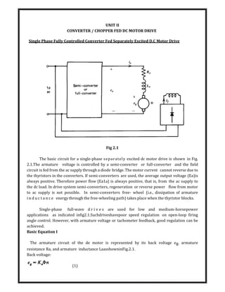
1. UNIT II
CONVERTER / CHOPPER FED DC MOTOR DRIVE
Single Phase Fully Controlled Converter Fed Separately Excited D.C Motor Drive
Fig 2.1
The basic circuit for a single-phase separately excited dc motor drive is shown in Fig.
2.1.The armature voltage is controlled by a semi-converter or full-converter and the field
circuit is fed from the ac supply through a diode bridge. The motor current cannot reverse due to
the thyristors in the converters. If semi-converters are used, the average output voltage (Ea)is
always positive. Therefore power flow (Ea1a) is always positive, that is, from the ac supply to
the dc load. In drive system semi-converters, regeneration or reverse power flow from motor
to ac supply is not possible. In semi-converters free- wheel (i.e., dissipation of armature
i n d u c t a n c e energy through the free-wheeling path) takes place when the thyristor blocks.
Single-phase full-wave d r i v e s are used for low and medium-horsepower
applications as indicated infig2.1.Suchdriveshavepoor speed regulation on open-loop firing
angle control. However, with armature voltage or tachometer feedback, good regulation can be
achieved.
Basic Equation I
The armature circuit of the de motor is represented by its back voltage eg, armature
resistance Ra, and armature inductance LaasshowninFig.2.1.
Back voltage:
(1)
3. Interms of average values,
(6)
Note that the inductance La does not absorb any average voltage. From eequation 2
and 6, the average speed is
In single-phase converters, the armature voltage ea and current t, change with time. This
is unlike the M-G set drive in which both ea and t, are essentially constant. In phase-controlled
converters, the armature current ia may not even be continuous. In fact, for most operating
conditions, t, is discontinuous. This makes prediction of performance difficult. Analysis is
simplified if continuity of armature current can be assumed. Analysis for both continuous and
discontinuous current is presented in the following sections
Continuous Armature Current
Let us assume that the armature current is continuous over the whole range of operation.
Typical voltage and current waveforms are shown in Figs.2.2 and 2.3 for semi-converter
and full-converter systems, respectively. The thyristors are symmetrically triggered. In the
semi-converter systemshowninFig.2.2, thyristor Sl is triggered at an angle a and S2atan
anglea+7T with respect to the supply voltage v. In the full-converter systemshowninFig.2.3,
thyristors S1, and S3 are simultaneously triggered at a, thyristors S2andS4aretriggeredat7T +a.
In Fig. 2.2, the motor is connected to the input supply for the period a<wt<7T through Sl
and D2, and the motor terminal voltage ea is the same as the supply input voltage v. Beyond 7T, ea
tends to reverse as the input voltage changes polarity. This will forward-bias the free-wheeling
diode and DFW w i l l start conducting. The motor current ia, which was flowing from the
supply through Sl' is transferred to DFW (i.e., Sl commutates). The motor terminals are
shorted through thefree-wheelingdiodeduring7T <wt <(7T +a), making zero. Energy from the
supply is therefore delivered to the armature
Circuit when the thyristor conducts (a to7T). This energy is partially stored in the
inductance, partially stored in the kinetic energy (K.E.) of the moving system, and partially
used to supply the mechanical load. During the free-wheeling period, 7T to7T +a, energy is
recovered from the inductance and is converted to mechanical form to supplement the K.E.in
supplying the mechanical load. The free- wheeling armature current continues to produce
electromagnetic torque in the motor. No energy is feedback to the supply during this period.
4. In Fig.2.3, the motor is always connected to the input supply through the thyristors.
Thyristors Sl and S3conduct during the interval a<wt <(7T +a) and connect the motor to the
supply. At 7T +a, thyristors S2 and S4aretriggered.Immediately the supply voltage appears across
the thyristors Sl and S3asareverse- bias voltage and turns them off. This is called natural or line
commutation. The motor current Ia, which was flowing from the supply through Sl and
S3'istransferred toS2and S4.During ato7T, energy flows from the input supply to the motor (both
v and Ia repositive, and eo and io are positive, signifying positive power flow). However, during
7T to 7T +a, some of the motor system energy is feedback to the input supply(v and I have
opposite polarities and likewise ea and io' signifying reverse power flow).
In Fig.2.3c voltage and current waveforms are shown for a firing angle greater than 90°.The
average motor terminal voltage Eo is negative. If the motor back emf Eg is reversed, it will
behave as a de- generator and will feed power back to the ac supply. This is known as the
inversion operation of the converter, and this mode of operation is used in the regenerative
5. braking of the motor.
Torque Speed Characteristics
For a semi-converter with free-wheeling action the armature circuit equations are:
Single-Phase Separately Excited DC Motor Drives
The armature circuit equation for a full-converter is:
6. DISCONTINUOUS ARMATURE CURRENT
The torque-speed characteristics shown in Fig.2.4b are drawn on the crude assumption
that the armature current is continuous over the whole range of operation. It is very doubtful
that the armature current will be continuous at high values of the firing angle a, high speed, and
low values of torque. In fact, armature current is discontinuous for these operating conditions. If
the armature current is discontinuous, the no-load speeds will be higher than those shown
in Fig.2.4b, and the speed regulation will be significantly poor in the region of discontinuous
armature current. The motor performance
7. . I
The waveforms with semi-converter and full-converter w i t h discontinuous
armature current areshowninFig.2.5andFig.2.6, respectively.
In Fig. 2.5, the motor is connected to the input supply for the period a<wI <71' through
S, and Dz.Beyond 71', the motor terminal is shorted through the free-wheeling diode DFW' The
armature current decays to zero at before the thyristor S2 is triggered at71' +a, thereby
making the armature current discontinuous. During a to 71' (i.e., the conduction period of the
8. thyristor S,), motor terminal voltage ea is the same as the supply voltage v. However, during the
motor current free-wheels through DFW and so ea s zero. The motor coasts and the motor
terminal voltage ea is the same as the back voltage InFig.2.6, the motor is connected to the supply
during a<wt<{3 and it Coasts during {3<wI <71' +a. As long as the motor is connected to the
supply, its terminal voltage is the same as the input supply voltage.
If the armature current can be assumed to be continuous, the torque-speed
characteristics can be calculated merely from average values ofthe motor terminal voltage and
current. In the discontinuous current mode, these calculations are cumbersome. The difficulty
arises in the calculation of the average motor terminal voltage Ea, because (called the extinction
angle, the instant at which the thyristor or motor current becomes zero) depends on, the
average speed N, average armature current la' and the firing angle a. A general approach,
valid for both continuous and discontinuous armature current, is therefore necessary.
Three Phase Fully Controlled Converter Fed Separately Excited D.C Motor Drive
Three phase controlled rectifiers are used in large power DC motor drives. Three phase
controlled rectifier gives more number of voltage per cycle of supply frequency. This makes motor
current continuous and filter requirement also less.
The number of voltage pulses per cycle depends upon the number of thyristors
and their connections for three phase controlled rectifiers. In three phase drives, the armature
circuit is connected to the output of a three phase controlled rectifier.
Three phase drives are used for high power applications up to megawatts power level.
The ripple frequency of armature voltage is greater than that of the single phase drives
and its requires less inductance in the armature circuit to reduce the armature current
ripple
Three phase full converter are used in industrial application up to 1500KW drives. It is
a two quadrant converter.
Principle of Operation
9. Three phase full converter bridge circuit connected across the armature terminals is
shown fig. The voltage and current waveforms of the converter. The circuit works as a three AC to
DC converter for firing angle delay 00
< α < 900
and as a line commutated inverter for 900
< α <
1800
. A three full converter fed DC motor is performed where generation of power is required.
10. Four Quadrant Operation of a Converters
The bi-directional boost converter is the IPQC version of the conventional thyristor dual
converters. Their topology is derived from ac-ac matrix converters using four quadrant
switches (4QSWs). Since no four-quadrant switch is currently commercially available the
realized by embedding a transistor inside a diode bridge or by inverse parallel connections of
transistors as shown in Fig (1). Power IGBT employed because they have the advantage so high
switching frequency and small pulse and notch widths. Topology of a single-phase bi-directional
boost converter using typeI 4QSWsis shown in Fig(2).
In the circuit shown in Fig (2), here are four4QSWs, two in each limb. Each 4QSW comprises two
2QSWs (two quadrant switches), each two-quadrant switch consisting of a IGBTT with series
diode, connected in inverse-parallel. The operation of the bi-directional boost converter in boost
11. mode and in a particular quadrant in the V-I plane shown in Fig (3) is determined by the
conditioning of the switching states of two sets (I and II) of devices. In the single-phase version
each set comprises four IGBTs; set(A) IGBTs–T11,T22,T33,T44 and set(B)I GBTTs-
T1,T2,T3,T4.corresponding to the four quadrants in the buck and boost modes pertaining to the
rectification and inversion operations
12. Time Ratio Control (TRC)
In this control scheme, time ratio Ton/T (duty ratio) is varied. This is realized by two
different ways called Constant Frequency System and Variable Frequency System as described
below:
Constant Frequency System
In this scheme, on-time is varied but chopping frequency f is kept constant. Variation of
Ton means adjustment of pulse width, as such this scheme is also called pulse-width-modulation
scheme.
Variable Frequency System
In this technique, the chopping frequency f is varied and either (i) on-time Ton is kept
constant or (ii) off-time Toff is kept constant. This method of controlling duty ratio is also
called Frequency- modulation scheme.
Current- Limit Control
In this control strategy, the on and off of chopper circuit is decided by the previous
set value of load current. The two set values are maximum load current and minimum load
current.
When the load current reaches the upper limit, chopper is switched off. When the
load current falls below lower limit, the chopper is switched on. Switching frequency of chopper
can be controlled by setting maximum and minimum level of current.
Current limit control involves feedback loop, the trigger circuit for the chopper is
therefore more complex. PWM technique is the commonly chosen control strategy for the power
control in chopper circuit
13. UNIT – II
TWO MARKS
1. What is the use of flywheel? Where it is used?
It is used for load equalization. It is mounted on the motor shaft in compound motor.
2. What are the advantages of series motor?
The advantages of series motors are,
High starting torque
Heavy torque overloads.
3. Define and mention different types of braking in a dc motor?
In breaking the motor works as a generator developing a negative torque which
opposes the motion. Types are regenerative braking, dynamic or rheostat braking and
plugging or reverse voltage braking.
4. How the D.C. motor is affected at the time of starting?
A D.C. motor is started with full supply voltage across its terminals, a very high
current will flow, which may damage the motor due to heavy sparking at commuter and
heating of the winding. Therefore, it is necessary top limit the current to a safe value
during starting.
5. List the drawbacks of armature resistance control?
In armature resistance control speed is varied by wasting power in external
resistors that are connected in series with the armature. since it is an inefficient method
of speed control it was used in intermittent load applications where the duration of
low speed operations forms only a small proportion of total running time.
6. What is static Ward-Leonard drive?
Controlled rectifiers are used to get variable d.c. voltage from an a.c. source of
fixed voltage controlled rectifier fed dc drives are also known as static Ward-Leonard
drive.
7. What is aline commutated inverter?
Full converter with firing angle delay greater than 90 deg. is called line
commutated inverter. such an operation is used in regenerative braking mode of a dc
motor in which case a back emf is greater than applied voltage.
8. Mention the methods of armature voltage controlled dc motor?
When the supplied voltage is ac,
Ward-Leonard schemes
Transformer with taps and un controlled rectifier bridge Static Ward-Leonard
scheme or controlled rectifiers
14. when the supply is dc:
Chopper control
9. How is the stator winding changed during constant torque and constant
horsepower operations?
For constant torque operation, the change of stator winding is made form
series - star to parallel - star, while for constant horsepower operation the change
is made from series-delta to parallel-star. Regenerative braking takes place during
changeover from higher to lower speeds.
10.Define positive and negative motor torque.
Positive motor torque is defined as the torque which produces acceleration or
the positive rate of change of speed in forward direction. Positive load torque is negative
if it produces deceleration.
11.Write the expression for average o/p voltage of full converter fed dc drives?
Vm=(2Vm/pi)cospi.........continuous conduction
Vm=[Vm(cos alpha-cos beta)+(pi+alpha+beta)]/pi] discontinuous conduction
12.What are the disadvantages of conventional Ward-Leonard schemes?
Higher initial cost due to use of two additional
mcs. Heavy weight and size.
Needs more floor space and proper foundation. Required frequent maintenance
13.Mention the drawbacks of rectifier fed dc drives?
Distortion of supply.
Low power factor.
Ripple in motor current
14.What are the advantages in operating choppers at high frequency?
The operation at a high frequency improves motor performance by reducing
current ripple and eliminating discontinuous conduction.
15.Why self commutated devices are preferred over thyristors for chopper circuits?
Self commutated devices such as power MOSFETs power transistors, IGBTs,
GTOs and IGCTs are preferred over thyristors for building choppers because they can
be commutated by a low power control signal and don't need commutation circuit.
16.State the advantages of dc chopper drives?
DC chopper device has the advantages of high efficiency, flexibility in control,
light weight, small size, quick response and regeneration down to very low speed.
15. 17.What are the advantages of closed loop c of dc drives?
Closed loop control system has the adv. of improved accuracy, fast dynamic
response and reduced effects of disturbance and system non-linearities.
18.What are the types of control strategies in dc chopper?
Time ratio control.
Current limit control.
19.What are the adv. of using PI controller in closed loop ctrl. of dc drive?
Stabilize the drive
Adjust the damping ratio at the desired value
Makes the steady state speed error close to zero by integral action and filters
out noise again due to the integral action.
20.What are the different methods of braking applied to the induction motor?
Regenerative braking
Plugging,
Dynamic braking.
21.What are the different methods of speed control of IM?
Stator voltage control, Supply frequency control, Rotor resistance control,
Slip power recovery control.
22.What is meant by stator voltage control.?
The speed of the IM can be changed by changing the stator voltage. Because
the torque is proportional to the square of the voltage.
23.Mention the application of stator voltage control.
This method is suitable for applications where torque demand reduced with speed,
which points towards its suitability for fan and pump drives.
24.Mention the applications of ac drives.
AC drives are used in a no. of applications such as fans, blowers, mill run-out
tables, cranes, conveyors, traction etc.
25.What are the three regions in the speed-torque characteristics in the IM?
Motoring region (0<=s<=1)
Generating region(s<0)
Plugging region (1<=s<=2) where s is the slip.
26.What are the advantages of stator voltage control method?
The control circuitry is simple
Compact size
Quick response time
16. There is considerable savings in energy and thus it is economical method as
compared to other methods of speed ctrl.
27.What is meant by soft start?
The ac voltage controllers show a step less control of supply voltage from zero to
rated voltage they are used for soft start for motors.
28.List the adv of squirrel cage IM?
Cheaper
light in weight
Rugged in construction
More efficient
Require less maintenance
It can be operated in dirty and explosive environment
29.Define slip
The difference between the synchronous speed (Ns)and actual speed(N)of the
rotor is known as slip speed. the % of slip is gn by,
%slip s=[(Ns-N)/Ns]x 100
30.Define base speed.
The synchronous speed corresponding to the rated freq is called the base speed.