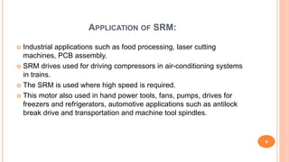
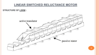
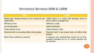
ANALYSIS OF LINEAR SWITCHED
RELUCTANCE MOTOR
1
Under the Guidance of :
Prof. Nisarg Dave
Presented by :
Akshay Lakhani (15BEE156)
Maulik Ankola (14BEE151)
CONTENTS :
 What is SRM?
 Construction and Working of SRM
 Application of SRM
 Working and Construction of LSRM
 Difference between SRM and LSRM
2
WHAT IS SRM ?
 Concept of SRM- Since 1969 (approx.)
 Also known as : -
Variable Reluctance Motor
Brushless Reluctance Motor
Commutated Reluctance Motor
 The switched reluctance motor (SRM) is a type of a stepper motor,
an electric motor that runs by reluctance torque. Unlike common
DC motor types, power is delivered to windings in the stator (case)
rather than the rotor.
3
SWITCHED RELUCTANCE MOTOR
4
Construction:
Three phase 6/4 pole SRM Physical structure of 10/8 SRM
 The Switched Reluctance Motor is a doubly Salient and Singly exited machine
with independent windings of the stator.
 The SRM has salient poles on both the rotor and the stator, but only the stator
poles carry windings.
 In Rotor pole no magnet and windings are present.
 Two rotor poles are aligned to the two stator poles, another set of rotor poles
is out of alignment with respect to a different set of stator poles.
 Two opposite side of stator pole is connected in Series.
 Material of core is laminated.
 Combinations of stator and rotor is 6/4.
Where, 6-Stator Poles
4-Rotor Poles
5
WORKING PRINCIPLE :-
6
Cycle Phase A Phase B Phase C Position
1 ON OFF OFF 0
OFF ON OFF 30
OFF OFF ON 60
2 ON OFF OFF 90
OFF ON OFF 120
OFF OFF ON 150
3 ON OFF OFF 180
0⁰ 30⁰ 60⁰
OPERATING WAVEFORM :
7
 La - Aligned Inductance
 Lu - Unaligned Inductance
 Ia* - Reference Current
 Ia - Actual Current
 ∆i – Hysteresis Window Band
APPLICATION OF SRM:
 Industrial applications such as food processing, laser cutting
machines, PCB assembly.
 SRM drives used for driving compressors in air-conditioning systems
in trains.
 The SRM is used where high speed is required.
 This motor also used in hand power tools, fans, pumps, drives for
freezers and refrigerators, automotive applications such as antilock
break drive and transportation and machine tool spindles.
6
LINEAR SWITCHED RELUCTANCE MOTOR
9
STRUCTURE OF LSRM :
CONSTRUCTION OF LSRM
10
Side view Front view
Translator
Stator
Direction of motionDirection of motion
WORKING OF LSRM
 Linear Switched Reluctance Motor works on the principle of switched reluctance
principle where the translator is made up of magnetic material which gets aligned to
a magnetic field so that the reluctance seen by the translator is minimum, thus for a
rotating type we see rotation and for a linear type we see linear translation.
 In linear SRM winding is on either Stator or Translator. In this case we considered
active stator and passive translator and longitudinal flux path configuration.
 The bearings are attached to translator and it is placed on channels and under that
phase windings are wound as to produce enough magnetic field for the motion of
translator.
 When first phase is excited at that time due to flow of current and a number of turns
on the stator teeth a magnetic field is produced, due to this magnetic field the
translator being a soft magnetic piece aligns itself to lowest reluctance path while
doing so a linear motion is achieved.
11
CONT..
 The phase excitation sequence is applied in a specific pattern then the translator will
start to move.
 In case of regenerative application proper excitation sequence is required in
opposite manner of motoring action.
 The LSRM may have either two stators or two translators or vice versa to make a
double-sided LSRM.
 The single sided linear SRM provides a net levitation force that can be exploited in
Maglev systems.
 The double sided LSRM does not produces a net levitation force; therefore it is
unsuitable for such applications.
 Its advantages are high force density and lower inductance, as it has four air gaps in
its flux path in the double sided linear SRM and two air gaps in flux path in the single
sided LSRM.
12
DIFFERENCE BETWEEN SRM & LSRM
13
SRM LSRM
Motors that develop torque to turn a shaft are just
called SRM.
LSRM refers to a motor that develops thrust to
drive a load in a straight line .
Efficiency is low. Efficiency is high.
Low Acceleration. High Acceleration
Power density is low. Power density is high.
Electrical fault in one phase affect other phases. Electrical fault in one phase does not affect other
phases.
More Power switches is required. It requires only unidirectional current for its four-
quadrant operation so no. of power switches can
be reduced.
POINTS COVERED IN NEXT REVIEW:
 Design of 6/4 SRM.
 Computation of all Parameter.
 Calculation of flux path and reluctance.
14
REFERENCES
 R. Krishnan, Switched Reluctance Motor Drives: Modelling, Simulation, Analysis, Design, and
Applications, CRC Press, 2001
 T. J. E. Miller, switched reluctance motors and their control, magna physics publishing and
clarendon press, oxford, 1993
 Linear Electric Machines, Drives, and MAGLEVs Handbook by ION BOLDEA
 Lloyd, J., SR drive applications, in Tutorial Course on Switched Reluctance Motor Drives,
organized by R. Krishnan, Conf. Rec. IEEE Ind. Appl. Soc. Ann. Mtg., Oct.,210–245, 1996.
 Switched reluctance drives for electric vehicle applications by P.Andrada, M.Torrent,
B.Blanqué, J.I.Perat
 EEP(Electrical Engineering Portal) http://electrical-engineering-portal.com/
15
16

DIFFERENCE BETWEEN SRM AND LSRM

  • 1.
    ANALYSIS OF LINEARSWITCHED RELUCTANCE MOTOR 1 Under the Guidance of : Prof. Nisarg Dave Presented by : Akshay Lakhani (15BEE156) Maulik Ankola (14BEE151)
  • 2.
    CONTENTS :  Whatis SRM?  Construction and Working of SRM  Application of SRM  Working and Construction of LSRM  Difference between SRM and LSRM 2
  • 3.
    WHAT IS SRM?  Concept of SRM- Since 1969 (approx.)  Also known as : - Variable Reluctance Motor Brushless Reluctance Motor Commutated Reluctance Motor  The switched reluctance motor (SRM) is a type of a stepper motor, an electric motor that runs by reluctance torque. Unlike common DC motor types, power is delivered to windings in the stator (case) rather than the rotor. 3
  • 4.
    SWITCHED RELUCTANCE MOTOR 4 Construction: Threephase 6/4 pole SRM Physical structure of 10/8 SRM
  • 5.
     The SwitchedReluctance Motor is a doubly Salient and Singly exited machine with independent windings of the stator.  The SRM has salient poles on both the rotor and the stator, but only the stator poles carry windings.  In Rotor pole no magnet and windings are present.  Two rotor poles are aligned to the two stator poles, another set of rotor poles is out of alignment with respect to a different set of stator poles.  Two opposite side of stator pole is connected in Series.  Material of core is laminated.  Combinations of stator and rotor is 6/4. Where, 6-Stator Poles 4-Rotor Poles 5
  • 6.
    WORKING PRINCIPLE :- 6 CyclePhase A Phase B Phase C Position 1 ON OFF OFF 0 OFF ON OFF 30 OFF OFF ON 60 2 ON OFF OFF 90 OFF ON OFF 120 OFF OFF ON 150 3 ON OFF OFF 180 0⁰ 30⁰ 60⁰
  • 7.
    OPERATING WAVEFORM : 7 La - Aligned Inductance  Lu - Unaligned Inductance  Ia* - Reference Current  Ia - Actual Current  ∆i – Hysteresis Window Band
  • 8.
    APPLICATION OF SRM: Industrial applications such as food processing, laser cutting machines, PCB assembly.  SRM drives used for driving compressors in air-conditioning systems in trains.  The SRM is used where high speed is required.  This motor also used in hand power tools, fans, pumps, drives for freezers and refrigerators, automotive applications such as antilock break drive and transportation and machine tool spindles. 6
  • 9.
    LINEAR SWITCHED RELUCTANCEMOTOR 9 STRUCTURE OF LSRM :
  • 10.
    CONSTRUCTION OF LSRM 10 Sideview Front view Translator Stator Direction of motionDirection of motion
  • 11.
    WORKING OF LSRM Linear Switched Reluctance Motor works on the principle of switched reluctance principle where the translator is made up of magnetic material which gets aligned to a magnetic field so that the reluctance seen by the translator is minimum, thus for a rotating type we see rotation and for a linear type we see linear translation.  In linear SRM winding is on either Stator or Translator. In this case we considered active stator and passive translator and longitudinal flux path configuration.  The bearings are attached to translator and it is placed on channels and under that phase windings are wound as to produce enough magnetic field for the motion of translator.  When first phase is excited at that time due to flow of current and a number of turns on the stator teeth a magnetic field is produced, due to this magnetic field the translator being a soft magnetic piece aligns itself to lowest reluctance path while doing so a linear motion is achieved. 11
  • 12.
    CONT..  The phaseexcitation sequence is applied in a specific pattern then the translator will start to move.  In case of regenerative application proper excitation sequence is required in opposite manner of motoring action.  The LSRM may have either two stators or two translators or vice versa to make a double-sided LSRM.  The single sided linear SRM provides a net levitation force that can be exploited in Maglev systems.  The double sided LSRM does not produces a net levitation force; therefore it is unsuitable for such applications.  Its advantages are high force density and lower inductance, as it has four air gaps in its flux path in the double sided linear SRM and two air gaps in flux path in the single sided LSRM. 12
  • 13.
    DIFFERENCE BETWEEN SRM& LSRM 13 SRM LSRM Motors that develop torque to turn a shaft are just called SRM. LSRM refers to a motor that develops thrust to drive a load in a straight line . Efficiency is low. Efficiency is high. Low Acceleration. High Acceleration Power density is low. Power density is high. Electrical fault in one phase affect other phases. Electrical fault in one phase does not affect other phases. More Power switches is required. It requires only unidirectional current for its four- quadrant operation so no. of power switches can be reduced.
  • 14.
    POINTS COVERED INNEXT REVIEW:  Design of 6/4 SRM.  Computation of all Parameter.  Calculation of flux path and reluctance. 14
  • 15.
    REFERENCES  R. Krishnan,Switched Reluctance Motor Drives: Modelling, Simulation, Analysis, Design, and Applications, CRC Press, 2001  T. J. E. Miller, switched reluctance motors and their control, magna physics publishing and clarendon press, oxford, 1993  Linear Electric Machines, Drives, and MAGLEVs Handbook by ION BOLDEA  Lloyd, J., SR drive applications, in Tutorial Course on Switched Reluctance Motor Drives, organized by R. Krishnan, Conf. Rec. IEEE Ind. Appl. Soc. Ann. Mtg., Oct.,210–245, 1996.  Switched reluctance drives for electric vehicle applications by P.Andrada, M.Torrent, B.Blanqué, J.I.Perat  EEP(Electrical Engineering Portal) http://electrical-engineering-portal.com/ 15
  • 16.