DSV TRAINING PRESENTATION II
MILLING AND WELL CONTROL
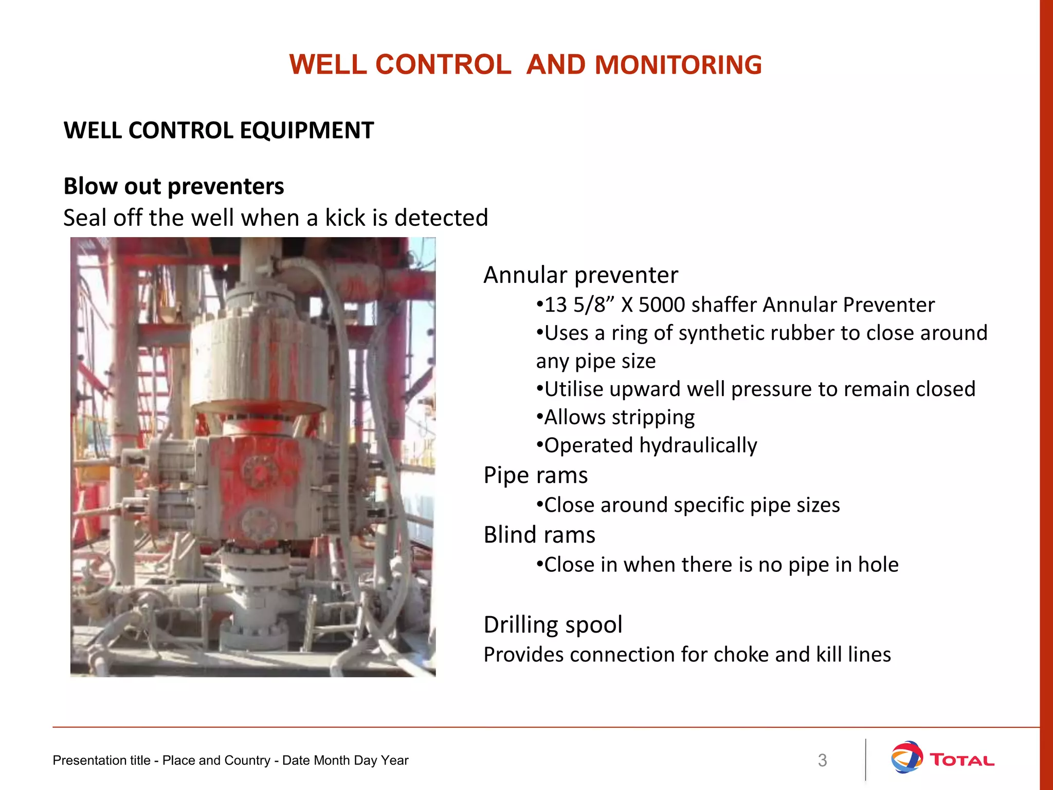
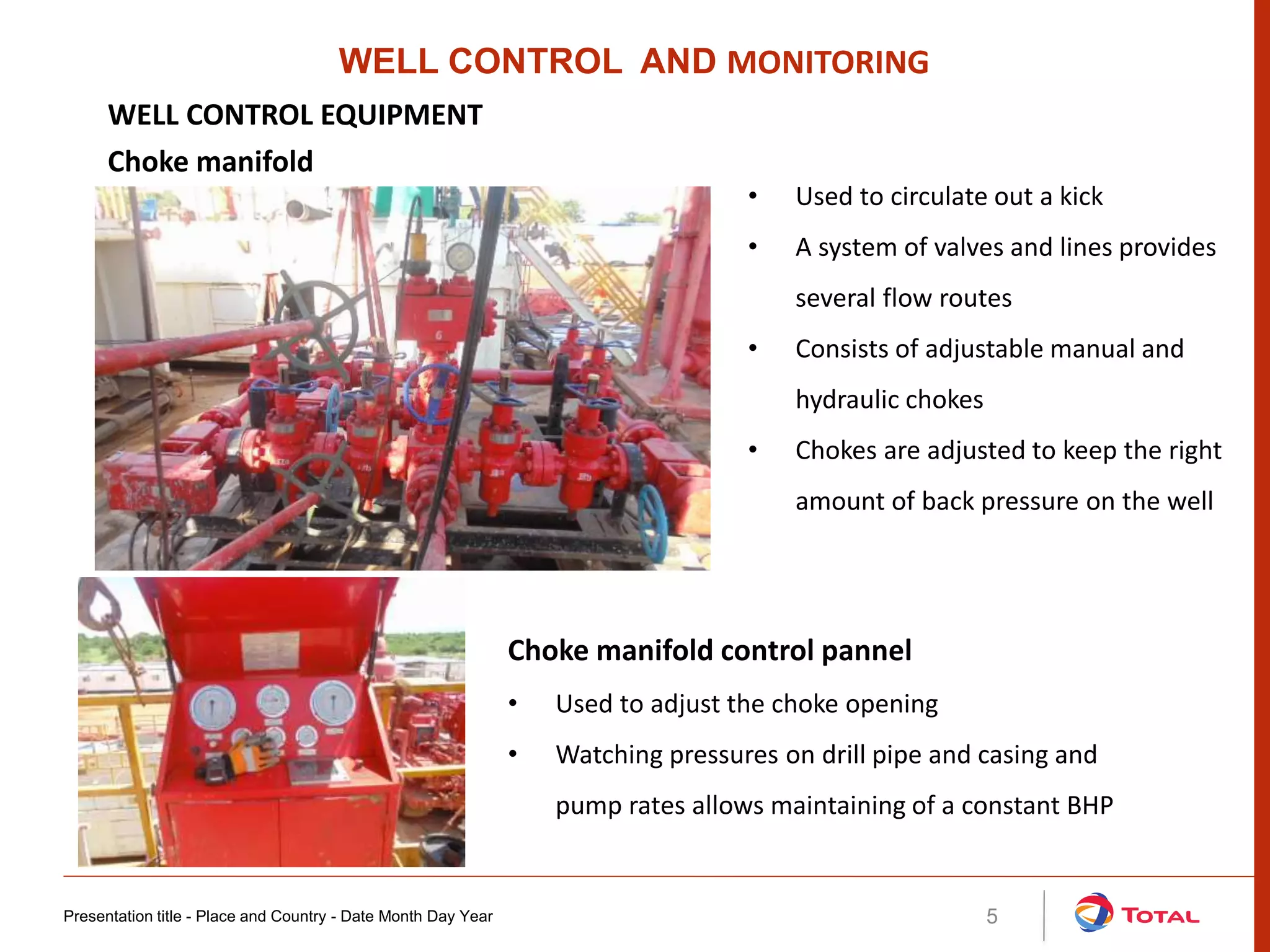
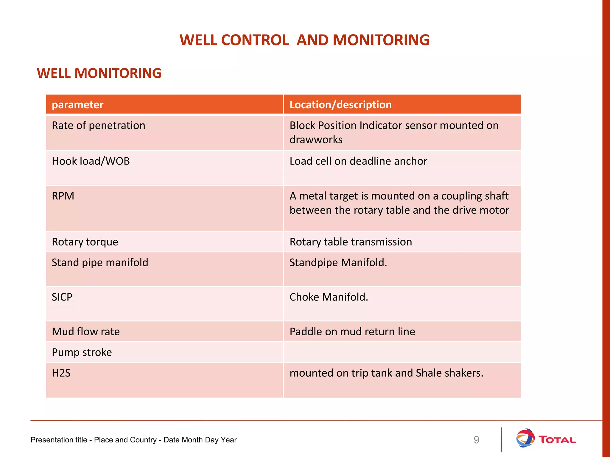
Kicks occur when formation pressures exceed mud hydrostatic pressure, formation
fluids enter well bore. Uncontrolled influx of formation fluids leads to blow out
Causes of kicks
• Failure to keep the hole full
• Insufficient mud density
• Swabbing during tripping
• Lost circulation
Detecting kicks
• Pit volume gain
• Increased flow on return line
• Drilling break
• Incorrect fill-up on trips
• Decrease in circulating pressure
• Shows of oil, gas or salt water
• increase in hook load
Presentation title - Place and Country - Date Month Day Year 2
WELL CONTROL AND MONITORING
KICKS AND BLOW OUT
Presentation title - Place and Country - Date Month Day Year 3
Annular preventer
•13 5/8” X 5000 shaffer Annular Preventer
•Uses a ring of synthetic rubber to close around
any pipe size
•Utilise upward well pressure to remain closed
•Allows stripping
•Operated hydraulically
Pipe rams
•Close around specific pipe sizes
Blind rams
•Close in when there is no pipe in hole
WELL CONTROL AND MONITORING
WELL CONTROL EQUIPMENT
Blow out preventers
Seal off the well when a kick is detected
Drilling spool
Provides connection for choke and kill lines
Presentation title - Place and Country - Date Month Day Year 4
Accumulator unit
Provides means of opening or closing the BOPs and HCR values
Accumulator bottles
•Maintains hydraulic fluid at high pressures
•10gallons Ea
•N2 at 1000Psi
•Operating pressure of 3000Psi
Pumps
•Electric pump automatically pumps hydraulic
fluid to maintain pressure in bottles
•Pneumatic pumps are backups
Reservoir
•Stores hydraulic fluid (1500L)
Pressure regulators
•control pressures to open annular and ram
preventers
WELL CONTROL AND MONITORING
WELL CONTROL EQUIPMENT
Driller’s bop control panel
Controls opening and closing of BOPs and choke line
Presentation title - Place and Country - Date Month Day Year 5
• Used to circulate out a kick
• A system of valves and lines provides
several flow routes
• Consists of adjustable manual and
hydraulic chokes
• Chokes are adjusted to keep the right
amount of back pressure on the well
WELL CONTROL AND MONITORING
WELL CONTROL EQUIPMENT
Choke manifold
Choke manifold control pannel
• Used to adjust the choke opening
• Watching pressures on drill pipe and casing and
pump rates allows maintaining of a constant BHP
Presentation title - Place and Country - Date Month Day Year 6
Separates gas from drilling mud
Design features
•Height and diameter to handle mud volumes
•Diameter and length of gas outlet
•Internal baffle plates for gas break out
•U-tube arrangement to maintain fluid head in
separator
WELL CONTROL AND MONITORING
WELL CONTROL EQUIPMENT
Poor boy Degasser
Equipment testing
• BOPs, choke and kill manifolds, choke and kill lines, accumulators must be regularly
pressure and function tested
• Low pressure test 500Psi X5min
• High pressure test 3000psi X10min
Drill string valves
• Kelly cock values
• Full opening safety valves (FOSV) or TIW
Presentation title - Place and Country - Date Month Day Year 7
WELL CONTROL AND MONITORING
WELL CONTROL EQUIPMENT
Trip tank
• Used when POOH or RIH
• Volumes in trip tanks are regularly monitored
• Pump fed
• Isolated from surface mud system to prevent gain or loss in case valves are left
open
Flow check
1. Disengage rotary and pick up kelly until tool joints clears rotary table
2. Shut down the mud pump
3. If there is no flow, resume operations. If well is flowing, shut in
Hard shut in
1. Close annular preventer with choke line closed
2. Open choke line with manifold chokes closed
3. Read SIDP and SICP
Presentation title - Place and Country - Date Month Day Year 8
SHUT IN PROCEDURE
WELL CONTROL AND MONITORING
Presentation title - Place and Country - Date Month Day Year 9
parameter Location/description
Rate of penetration Block Position Indicator sensor mounted on
drawworks
Hook load/WOB Load cell on deadline anchor
RPM A metal target is mounted on a coupling shaft
between the rotary table and the drive motor
Rotary torque Rotary table transmission
Stand pipe manifold Standpipe Manifold.
SICP Choke Manifold.
Mud flow rate Paddle on mud return line
Pump stroke
H2S mounted on trip tank and Shale shakers.
WELL CONTROL AND MONITORING
WELL MONITORING

Dk well control

  • 1.
    DSV TRAINING PRESENTATIONII MILLING AND WELL CONTROL
  • 2.
    Kicks occur whenformation pressures exceed mud hydrostatic pressure, formation fluids enter well bore. Uncontrolled influx of formation fluids leads to blow out Causes of kicks • Failure to keep the hole full • Insufficient mud density • Swabbing during tripping • Lost circulation Detecting kicks • Pit volume gain • Increased flow on return line • Drilling break • Incorrect fill-up on trips • Decrease in circulating pressure • Shows of oil, gas or salt water • increase in hook load Presentation title - Place and Country - Date Month Day Year 2 WELL CONTROL AND MONITORING KICKS AND BLOW OUT
  • 3.
    Presentation title -Place and Country - Date Month Day Year 3 Annular preventer •13 5/8” X 5000 shaffer Annular Preventer •Uses a ring of synthetic rubber to close around any pipe size •Utilise upward well pressure to remain closed •Allows stripping •Operated hydraulically Pipe rams •Close around specific pipe sizes Blind rams •Close in when there is no pipe in hole WELL CONTROL AND MONITORING WELL CONTROL EQUIPMENT Blow out preventers Seal off the well when a kick is detected Drilling spool Provides connection for choke and kill lines
  • 4.
    Presentation title -Place and Country - Date Month Day Year 4 Accumulator unit Provides means of opening or closing the BOPs and HCR values Accumulator bottles •Maintains hydraulic fluid at high pressures •10gallons Ea •N2 at 1000Psi •Operating pressure of 3000Psi Pumps •Electric pump automatically pumps hydraulic fluid to maintain pressure in bottles •Pneumatic pumps are backups Reservoir •Stores hydraulic fluid (1500L) Pressure regulators •control pressures to open annular and ram preventers WELL CONTROL AND MONITORING WELL CONTROL EQUIPMENT Driller’s bop control panel Controls opening and closing of BOPs and choke line
  • 5.
    Presentation title -Place and Country - Date Month Day Year 5 • Used to circulate out a kick • A system of valves and lines provides several flow routes • Consists of adjustable manual and hydraulic chokes • Chokes are adjusted to keep the right amount of back pressure on the well WELL CONTROL AND MONITORING WELL CONTROL EQUIPMENT Choke manifold Choke manifold control pannel • Used to adjust the choke opening • Watching pressures on drill pipe and casing and pump rates allows maintaining of a constant BHP
  • 6.
    Presentation title -Place and Country - Date Month Day Year 6 Separates gas from drilling mud Design features •Height and diameter to handle mud volumes •Diameter and length of gas outlet •Internal baffle plates for gas break out •U-tube arrangement to maintain fluid head in separator WELL CONTROL AND MONITORING WELL CONTROL EQUIPMENT Poor boy Degasser Equipment testing • BOPs, choke and kill manifolds, choke and kill lines, accumulators must be regularly pressure and function tested • Low pressure test 500Psi X5min • High pressure test 3000psi X10min
  • 7.
    Drill string valves •Kelly cock values • Full opening safety valves (FOSV) or TIW Presentation title - Place and Country - Date Month Day Year 7 WELL CONTROL AND MONITORING WELL CONTROL EQUIPMENT Trip tank • Used when POOH or RIH • Volumes in trip tanks are regularly monitored • Pump fed • Isolated from surface mud system to prevent gain or loss in case valves are left open
  • 8.
    Flow check 1. Disengagerotary and pick up kelly until tool joints clears rotary table 2. Shut down the mud pump 3. If there is no flow, resume operations. If well is flowing, shut in Hard shut in 1. Close annular preventer with choke line closed 2. Open choke line with manifold chokes closed 3. Read SIDP and SICP Presentation title - Place and Country - Date Month Day Year 8 SHUT IN PROCEDURE WELL CONTROL AND MONITORING
  • 9.
    Presentation title -Place and Country - Date Month Day Year 9 parameter Location/description Rate of penetration Block Position Indicator sensor mounted on drawworks Hook load/WOB Load cell on deadline anchor RPM A metal target is mounted on a coupling shaft between the rotary table and the drive motor Rotary torque Rotary table transmission Stand pipe manifold Standpipe Manifold. SICP Choke Manifold. Mud flow rate Paddle on mud return line Pump stroke H2S mounted on trip tank and Shale shakers. WELL CONTROL AND MONITORING WELL MONITORING