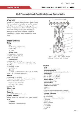
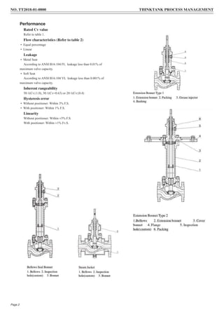
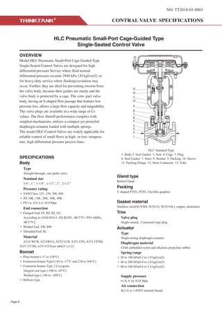
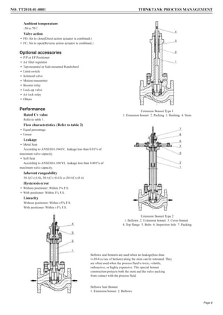
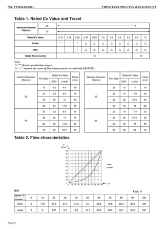
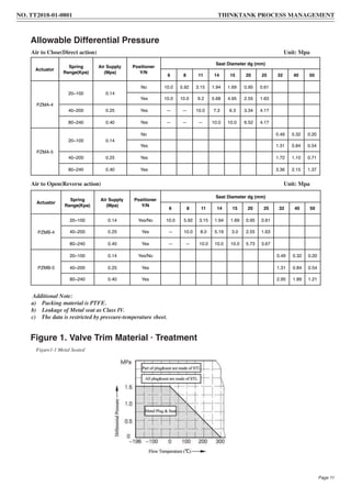
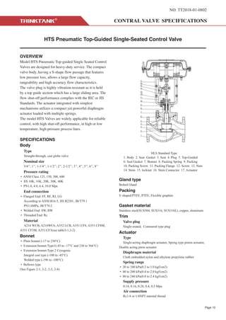
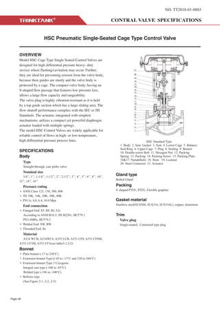
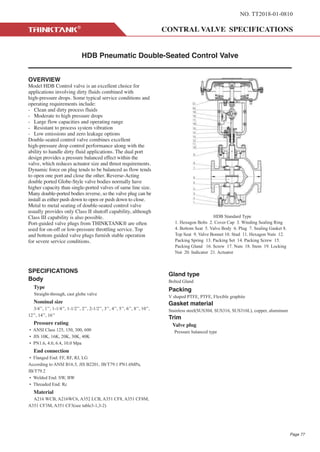
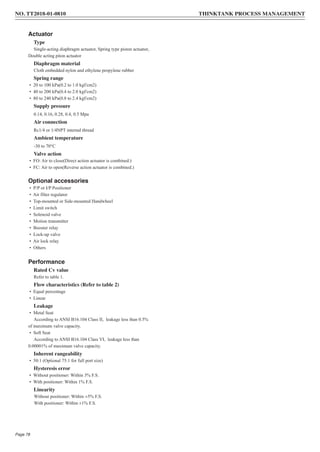
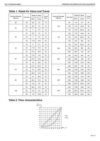
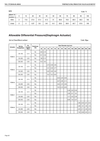
THINKTANK®️ is the leading manufacturer of control valves in China, we focus on the production and development of pneumatic or electric globe type control valves, self-operated pressure regulator and double-seat control valves
3. NO. TT2018-01-0800
HLS Pneumatic Small-Port Single-Seated Control Valve
OVERVIEW
Model HLS Pneumatic Small-Port Single-Seated Control
Valve are designed for heavy duty service. The compact
valve body, having and S-shape flow passage that
features low pressure loss, allows a large flow capacity,
rangeability and high accuracy flow characteristics.
Furnished by multi-spring diaphragm actuator, the
control valve is compact in structure and big in output
force.
SPECIFICATIONS
Body
Type
Straight-through, cast globe valve
Nominal size
3/4, 1 inch
Pressure rating
• ANSI Class 125, 150, 300, 600
• JIS 10K, 16K, 20K, 30K, 40K
• PN1.6, 4.0, 6.4 Mpa
End connection
• Flanged End: FF, RF, RJ, LG
According to ANSI B16.5, JIS B2201, JB/T79.1 PN1.6MPa,
JB/T79.2
• Welded End: SW, BW
• Threaded End: Rc
Material
A216 WCB, A216WC6, A352 LCB, A351 CF8, A351 CF8M,
A351 CF3M, A351 CF3(see table3-1,3-2)
Bonnet
• Plain bonnet (-17 to 230°C)
• Extension bonnet Type1(-45 to -17°C and 230 to 566°C)
• Extension bonnet Type 2 Cryogenic
Integral cast type (-100 to -45°C)
Welded type (-196 to -100°C)
• Bellows type
Gland type
Bolted Gland
Packing
V shaped PTFE, PTFE, Flexible graphite
Gasket material
Stainless steel(SUS304, SUS316, SUS316L), copper, aluminum
Trim
Valve plug
Single-seated, Contoured type plug
Actuator
Type
Single-acting diaphragm actuator
Diaphragm material
Cloth embedded nylon and ethylene propylene rubber
Spring range
• 20 to 100 kPa(0.2 to 1.0 kgf/cm2)
• 40 to 200 kpa(0.4 to 2.0 kgf/cm2)
• 80 to 240 kPa(0.8 to 2.4 kgf/cm2)
Supply pressure
0.14, 0.16, 0.28, 0.40 Mpa
Air connection
Rc1/4 or 1/4NPT internal thread
Ambient temperature
-30 to 70°C
Valve action
• FO: Air to close(Direct action actuator is combined.)
• FC: Air to open(Reverse action actuator is combined.)
Optional accessories
• P/P or I/P Positioner
• Air filter regulator
• Top-mounted or Side-mounted Handwheel
• Limit switch
• Solenoid valve
• Motion transmitter
• Booster relay
• Lock-up valve
• Air lock relay
• Others
HLS Standard Type
1. Body 2. Seat 3. Plug 4. Bonnet 5. Stem
6. Packing 7. Indicator scale 8. Actuator
Page 1
4. Performance
Rated Cv value
Refer to table 1.
Flow characteristics (Refer to table 2)
• Equal percentage
• Linear
Leakage
• Metal Seat
According to ANSI B16.104 IV, leakage less than 0.01% of
maximum valve capacity.
• Soft Seat
According to ANSI B16.104 VI, leakage less than 0.001% of
maximum valve capacity.
Inherent rangeability
50:1(Cv≥1.0), 30:1(Cv=0.63) or 20:1(Cv≤0.4)
Hysteresis error
• Without positioner: Within 3% F.S.
• With positioner: Within 1% F.S.
Linearity
Without positioner: Within ±5% F.S.
With positioner: Within ±1% Fv.S.
NO. TT2018-01-0800 THINKTANK PROCESS MANAGEMENT
Page 2
5. Nominal Diameter DN(mm)
20
25
Rated Cv Value 0.16 0.25 0.40 0.63 1.0 1.6 2.5 4.0 7.37 11.7
Metal Seat
Linear * *
EQ% *
Soft Seat
Linear * * * * * * * * * *
EQ% * * * * * * * * *
Actuator Model
Direct action PZMA-4
Reverse action PZMB-4
Rated Travel L(mm) 16
Eff. Area(cm2) 280
Nominal Pressure
PN(Mpa) 1.6, 4.0, 6.4, 10.0
ANSI 150LB, 300LB, 600
Inherent Flow Characteristics Linear, EQ%
Inherent rangeability 20:1 30:1 50:1
Spring Range Pr(Kpa) 20~100, 40~200, 80~240
Air Supply Ps(Mpa) 0.14, 0.25, 0.4
Table 2. Flow characteristics
Table 1. Rated Cv Value and Travel
Note:
1) “*” denotes production ranges.
2) “△” denotes the curve of flow characteristics accord with GB/T4213.
3) Please select model HLS for values of rated Cv 0.01, 0.04, 0.1
NO. TT2018-01-0800 THINKTANK PROCESS MANAGEMENT
Page 3
6. Allowable Differential Pressure Table for Soft Seat Type Unit: Mpa
Action Type Actuator
Spring
Range(Kpa)
Air Supply
(Mpa)
Positioner
Y/N
Rated Cv Value
0.25 0.40 0.63 1.0 1.6 2.5 4.0 7.37 11.7
Direct PZMA-4
20~100 0.14
No _ 2.0 2.0 2.0 2.0 1.4 1.4 1.2 0.76
Yes _ 3.0 3.0 3.0 3.0 3.0 3.0 2.78 1.78
40~200 0.25 Yes _ 3.0 3.0 3.0 3.0 3.0 3.0 3.0 2.29
80~240 0.40 Yes _ _ _ _ _ _ _ _ 3.00
Reverse PZMB-4
20~100 0.14 Yes/No _ 2.0 2.0 2.0 2.0 1.4 1.4 1.19 0.76
40~200 0.25 Yes _ 3.0 3.0 3.0 3.0 3.0 3.0 2.78 1.78
80~240 0.40 Yes _ _ _ _ _ _ _ 3.00 3.00
Action Type Actuator
Spring
Range(Kpa)
Air Supply
(Mpa)
Positioner
Y/N
Rated Cv Value
0.2
5
0.40 0.63 1.0 1.6 2.5 4.0 7.37 11.7
Direct PZMA-4
20~100 0.14
No
3.0
10.0
3.0
5.92
3.0
5.92
3.0
3.15
3.0
3.15
1.94 1.69 0.95 0.61
Yes
3.0
10.0
3.0
10.0
3.0
10.0
3.0
9.2
3.0
10.0
3.0
5.68
3.0
4.95
2.55 1.63
40~200 0.25 Yes _ _ _
3.0
10.0
3.0
10.0
3.0
7.30
3.0
6.3
3.0
3.34
2.14
80~240 0.40 Yes _ _ _ _ _
3.0
10.0
3.0
10.0
3.0
6.52
4.17
Reverse PZMB-4
20~100 0.14 Yes/No
3.0
10.0
3.0
5.92
3.0
5.92
3.0
3.15
3.0
3.15
1.94 1.69 0.95 0.61
40~200 0.25 Yes _
3.0
10.0
3.0
10.0
3.0
3.15
3.0
8.0
3.0
5.19
3.0 2.55 1.63
80~240 0.40 Yes _ _ _
3.0
10.0
3.0
10.0
3.0
10.0
3.0
10.0
3.0
5.73
3.67
Allowable Differential Pressure
Allowable Differential Pressure Table for Metal Seat Type
Unit: Mpa
Additional Note:
a) Packing material is PTFE.
b) Leakage of Metal seat as Class IV.
c) The upper figures denote the operating allowable differential pressure. The lower denote allowable differential
pressure at full
closure.
d) When liquid service, the operating allowable differential pressure of liquid exceeds 3.0Mpa {30 kgf/cm2}, we
recommend to use
model HLC.
e) The data is restricted by pressure-temperature sheet.
NO. TT2018-01-0800 THINKTANK PROCESS MANAGEMENT
Page 4
7. Pressure-Temperature Sheet
Working Temperature Range and Seat Leakage
Table 3-1 Valve Body Material: Stainless Steel
Table 3-1 Valve Body Material: Carbon Steel
Valve Body Material WCB, WCC, WC6, WC9, LCB
Trim
Material 304/316 304/316 304/316 304/316
Treatment RPTFE — ST SS
Seat
Material 304/316 304/316 304/316 304/316
Treatment — — ST SS
Allowable
Leakage
Class V/VI IV IV/V/VI IV/V/VI
Standard GB/T4213, FCI70.2, ANSI B16.104
Working
Temperature( )
WCB, WCC -5 ~ +160 -5 ~ +230 -5 ~ +425 -5 ~ +425
WC6, WC9 -5 ~ +160 -5 ~ +230 -5 ~ +538 -5 ~ +538
LCB -45 ~ +160 -45 ~ +230 -45 ~ +350 -45 ~ +350
Valve Body Material CF3, CF8, CF3M, CF8M
Trim
Material 304/316 304/316 304/316 304/316
Treatment RPTFE — ST SS
Seat
Material 304/316 304/316 304/316 304/316
Treatment — — ST SS
Allowable
Leakage
Class V/VI IV IV/V/VI IV/V/VI
Standard GB/T4213, FCI70.2, ANSI B16.104
Working
Temperature( )
-45 ~ +160 -196 ~ +538 -196 ~ +538 -196 ~ +538
NO. TT2018-01-0800 THINKTANK PROCESS MANAGEMENT
Page 5
8. External Dimensions for Standard, Bellows and Extension
Unit: mm
Nominal Diameter
DN(mm)
ANSI 150RF, JIS 10K FF, RF
PN1.6Mpa
ANSI 300 RF,
JIS 20K, 30K
RF, PN4.0
ANSI 600 RF, JIS 40K RF,
PN6.4, PN10.0
H5 H6 C A GW(kg)
L H1 H2 H3 L L H1 H2 H3
20 184 130 45 251 194 194 140 48 260
258 180 220 282
21
25 184 130 48 251 197 197 140 48 260 22
NO. TT2018-01-0800 THINKTANK PROCESS MANAGEMENT
Page 6
9. Unit: mm
Unit: mm
External Dimensions for Steam Jacket
External Dimensions for Extension Type 2
Nominal Diameter
DN(mm)
L A H1 H2 H3 H5 H6 L1 L2 C Flange
20 230 282 140 258 220 45 180 50 70 220 40
25 230 282 140 258 220 50 180 50 70 220 40
Nominal Diameter
DN(mm)
L
A H1 H2 H3 H5 D3 D4 n-M D5 X Y C H6 Flange
150LB 300LB 600LB
20 184 194 194
282 700 58 69 42 260 290
8-
M12
285 2.5 45 220 180
40
25 184 197 197 40
NO. TT2018-01-0800 THINKTANK PROCESS MANAGEMENT
Page 7
10. NO. TT2018-01-0801
HLC Pneumatic Small-Port Cage-Guided Type
Single-Seated Control Valve
OVERVIEW
Model HLC Pneumatic Small-Port Cage-Guided Type
Single-Seated Control Valves are designed for high
differential pressure Service where fluid normal
differential pressure exceeds 2940 kPa {30 kgf/cm2} or
for heavy-duty service where flashing/cavitation may
occur. Further, they are ideal for preventing erosion from
the valve body, because their guides are sturdy and the
valve body is protected by a cage. The com- pact valve
body, having an S-shaped flow passage that features low
pressure loss, allows a large flow capacity and rangeability.
The valve plugs are available in a wide range of Cv
values. The flow shutoff performance complies with
simplest mechanisms, utilizes a compact yet powerful
diaphragm actuator loaded with multiple springs.
The model HLC Control Valves are widely applicable for
reliable control of small flows in high- or low- tempera-
ture, high differential pressure process lines.
SPECIFICATIONS
Body
Type
Straight-through, cast globe valve
Nominal size
3/4’’, 1’’, 1-1/4’’, 1-1/2’’, 2’’, 2-1/2’’
Pressure rating
• ANSI Class 125, 150, 300, 600
• JIS 10K, 16K, 20K, 30K, 40K
• PN1.6, 4.0, 6.4, 10.0 Mpa
End connection
• Flanged End: FF, RF, RJ, LG
According to ANSI B16.5, JIS B2201, JB/T79.1 PN1.6MPa,
JB/T79.2
• Welded End: SW, BW
• Threaded End: Rc
Material
A216 WCB, A216WC6, A352 LCB, A351 CF8, A351 CF8M,
A351 CF3M, A351 CF3(see table3-1,3-2)
Bonnet
• Plain bonnet (-17 to 230°C)
• Extension bonnet Type1(-45 to -17°C and 230 to 566°C)
• Extension bonnet Type 2 Cryogenic
Integral cast type (-100 to -45°C)
Welded type (-196 to -100°C)
• Bellows type
Gland type
Bolted Gland
Packing
V shaped PTFE, PTFE, Flexible graphite
Gasket material
Stainless steel(SUS304, SUS316, SUS316L), copper, aluminum
Trim
Valve plug
Single-seated, Contoured type plug
Actuator
Type
Single-acting diaphragm actuator
Diaphragm material
Cloth embedded nylon and ethylene propylene rubber
Spring range
• 20 to 100 kPa(0.2 to 1.0 kgf/cm2)
• 40 to 200 kPa(0.4 to 2.0 kgf/cm2)
• 80 to 240 kPa(0.8 to 2.4 kgf/cm2)
Supply pressure
0.14, 0.16, 0.28 Mpa
Air connection
Rc1/4 or 1/4NPT internal thread
HLC Standard Type
1. Body 2. Seat Gasket 3. Seat 4. Cage 5. Plug
6. Seal Gasket 7. Stem 8. Bonnet 9. Packing 10. Sleeve
11. Packing Flange 12. Stem Connector 13. Yoke
Page 8
11. Ambient temperature
-30 to 70℃
Valve action
• FO: Air to close(Direct action actuator is combined.)
• FC: Air to open(Reverse action actuator is combined.)
Optional accessories
• P/P or I/P Positioner
• Air filter regulator
• Top-mounted or Side-mounted Handwheel
• Limit switch
• Solenoid valve
• Motion transmitter
• Booster relay
• Lock-up valve
• Air lock relay
• Others
Performance
Rated Cv value
Refer to table 1.
Flow characteristics (Refer to table 2)
• Equal percentage
• Linear
Leakage
• Metal Seat
According to ANSI B16.104 IV, leakage less than 0.01% of
maximum valve capacity.
• Soft Seat
According to ANSI B16.104 VI, leakage less than 0.001% of
maximum valve capacity.
Inherent rangeability
50:1(Cv≥1.0), 30:1(Cv=0.63) or 20:1(Cv≤0.4)
Hysteresis error
• Without positioner: Within 3% F.S.
• With positioner: Within 1% F.S.
Linearity
Without positioner: Within ±5% F.S.
With positioner: Within ±1% F.S.
Extension Bonnet Type 1
1. Extension bonnet 2. Packing 3. Bushing 4. Stem
Extension Bonnet Type 2
1. Bellows 2. Extension bonnet 3. Cover bonnet
4. Top flange 5. Bolts 6. Inspection hole 7. Packing
Bellows seal bonnets are used when no leakage(less than
1x10⁻⁶ cc/sec of helium) along the stem can be tolerated. They
are often used when the process fluid is toxic, volatile,
radioactive, or highly expensive. This special bonnet
construction protects both the stem and the valve packing
from contact with the process fluid.
Bellows Seal Bonnet
1. Extension bonnet 2. Bellows
NO. TT2018-01-0801 THINKTANK PROCESS MANAGEMENT
Page 9
13. Allowable Differential Pressure
Figure 1. Valve Trim Material · Treatment
Additional Note:
a) Packing material is PTFE.
b) Leakage of Metal seat as Class IV.
c) The data is restricted by pressure-temperature sheet.
Figure1-1 Metal Seated
Air to Close(Direct action) Unit: Mpa
Air to Open(Reverse action) Unit: Mpa
Actuator
Spring
Range(Kpa)
Air Supply
(Mpa)
Positioner
Y/N
Seat Diameter dg (mm)
6 8 11 14 15 20 25 32 40 50
PZMA-4
20~100 0.14
No 10.0 5.92 3.15 1.94 1.69 0.95 0.61
Yes 10.0 10.0 9.2 5.68 4.95 2.55 1.63
40~200 0.25 Yes — — 10.0 7.3 6.3 3.34 4.17
80~240 0.40 Yes — — — 10.0 10.0 6.52 4.17
PZMA-5
20~100 0.14
No 0.49 0.32 0.20
Yes 1.31 0.84 0.54
40~200 0.25 Yes 1.72 1.10 0.71
80~240 0.40 Yes 3.36 2.15 1.37
Actuator
Spring
Range(Kpa)
Air Supply
(Mpa)
Positioner
Y/N
Seat Diameter dg (mm)
6 8 11 14 15 20 25 32 40 50
PZMB-4
20~100 0.14 Yes/No 10.0 5.92 3.15 1.94 1.69 0.95 0.61
40~200 0.25 Yes — 10.0 8.0 5.19 3.0 2.55 1.63
80~240 0.40 Yes — — 10.0 10.0 10.0 5.73 3.67
PZMB-5
20~100 0.14 Yes/No 0.49 0.32 0.20
40~200 0.25 Yes 1.31 0.84 0.54
80~240 0.40 Yes 2.95 1.89 1.21
NO. TT2018-01-0801 THINKTANK PROCESS MANAGEMENT
Page 11
14. Figure 2. Working Temperature of Packing Material · Pressure Ranges
Working Temperature Range and Seat Leakage
Figure 2-1 V-Type RPTFE Figure 2-2 PTFE+Carbon Fiber/PTFE+Asbestos Figure 2-3 Flexible Graphite
Table 3-2 Valve Body Material: Stainless Steel
Table 3-1 Valve Body Material: Carbon Steel
Valve Body Material WCB, WCC, WC6, WC9, LCB
Trim
Material 304/316 304/316 304/316
Treatment — ST SS
Seat
Material 304/316 304/316 304/316
Treatment — ST SS
Allowable Leakage
Class IV IV/V/VI IV/V/VI
Standard GB/T4213, FCI70.2, ANSI B16.104
Working
Temperature( )
WCB, WCC -5 ~ +230 -5 ~ +425 -5 ~ +425
WC6, WC9 -5 ~ +230 -5 ~ +538 -5 ~ +538
LCB -45 ~ +230 -45 ~ +350 -45 ~ +350
Valve Body Material CF3, CF8, CF3M, CF8M
Trim
Material 304/316 304/316 304/316
Treatment — ST ST
Seat
Material 304/316 304/316 304/316
Treatment — ST SS
Allowable Leakage
Class IV IV/V/VI IV/V/VI
Standard GB/T4213, FCI70.2, ANSI B16.104
Working
Temperature( )
-196 ~ +538 -196 ~ +538 -196 ~ +538
NO. TT2018-01-0801 THINKTANK PROCESS MANAGEMENT
Page 12
17. NO. TT2018-01-0802
HTS Pneumatic Top-Guided Single-Seated Control Valve
OVERVIEW
Model HTS Pneumatic Top-guided Single Seated Control
Valves are designed for heavy-duty service. The compact
valve body, having a S-shape flow passage that features
low pressure loss, allows a large flow capacity,
rangeability and high accuracy flow characteristics.
The valve plug is highly vibration-resistant as it is held
by a top guide section which has a large sliding area. The
flow shut-off performance complies with the IEC or JIS
Standards. The actuator integrated with simplest
mechanisms utilizes a compact yet powerful diaphragm
actuator loaded with multiple springs.
The model HTS Valves are widely applicable for reliable
control, with high shut-off performance, in high or low
temperature, high pressure process lines.
SPECIFICATIONS
Body
Type
Straight-through, cast globe valve
Nominal size
3/4’’, 1’’, 1-1/4’’, 1-1/2’’, 2’’, 2-1/2’’, 3’’, 4’’, 5’’, 6’’, 8’’
Pressure rating
• ANSI Class 125, 150, 300, 600
• JIS 10K, 16K, 20K, 30K, 40K
• PN1.6, 4.0, 6.4, 10.0 Mpa
End connection
• Flanged End: FF, RF, RJ, LG
According to ANSI B16.5, JIS B2201, JB/T79.1
PN1.6MPa, JB/T79.2
• Welded End: SW, BW
• Threaded End: Rc
Material
A216 WCB, A216WC6, A352 LCB, A351 CF8, A351 CF8M,
A351 CF3M, A351 CF3(see table3-1,3-2)
Bonnet
• Plain bonnet (-17 to 230°C)
• Extension bonnet Type1(-45 to -17°C and 230 to 566°C)
• Extension bonnet Type 2 Cryogenic
Integral cast type (-100 to -45°C)
Welded type (-196 to -100°C)
• Bellows type
(See Figure 2-1, 2-2, 2-3, 2-4)
Gland type
Bolted Gland
Packing
V shaped PTFE, PTFE, Flexible graphite
Gasket material
Stainless steel(SUS304, SUS316, SUS316L), copper, aluminum
Trim
Valve plug
Single-seated, Contoured type plug
Actuator
Type
Single-acting diaphragm actuator, Spring type piston actuator,
Double acting piton actuator
Diaphragm material
Cloth embedded nylon and ethylene propylene rubber
Spring range
• 20 to 100 kPa(0.2 to 1.0 kgf/cm2)
• 40 to 200 kPa(0.4 to 2.0 kgf/cm2)
• 80 to 240 kPa(0.8 to 2.4 kgf/cm2)
Supply pressure
0.14, 0.16, 0.28, 0.4, 0.5 Mpa
Air connection
Rc1/4 or 1/4NPT internal thread
HLS Standard Type
1. Body 2. Seat Gasket 3. Seat 4. Plug 5. Top-Guided
6. Seal Gasket 7. Bonnet 8. Packing Spring 9. Packing
10. Packing Screw 11. Packing Flange 12. Screw 13. Nuts
14. Stem 15. locknut 16. Stem Connector 17. Actuator
Page 15
18. Ambient temperature
-30 to 70℃
Valve action
• FO: Air to close(Direct action actuator is combined.)
• FC: Air to open(Reverse action actuator is combined.)
Optional accessories
• P/P or I/P Positioner
• Air filter regulator
• Top-mounted or Side-mounted Handwheel
• Limit switch
• Solenoid valve
• Motion transmitter
• Booster relay
• Lock-up valve
• Air lock relay
• Others
Performance
Rated Cv value
Refer to table 1.
Flow characteristics (Refer to table 2)
• Equal percentage
• Linear
Leakage
• Metal Seat
According to ANSI B16.104 IV, leakage less than 0.01% of
maximum valve capacity.
• Soft Seat
According to ANSI B16.104 Class VI, leakage less than
0.00001% of maximum valve capacity.
Inherent rangeability
• 50:1
• 75:1
Hysteresis error
• Without positioner: Within 3% F.S.
• With positioner: Within 1% F.S.
Linearity
Without positioner: Within ±5% F.S.
With positioner: Within ±1% F.S.
Figure a-a. Plug
(Sealing surface RPTFE)
Figure a-b. Plug
(Sealing surface welding Stellite)
Page 16
NO. TT2018-01-0802 THINKTANK PROCESS MANAGEMENT
30. NO. TT2018-01-0803
HSC Pneumatic Single-Seated Cage Type Control Valve
OVERVIEW
Model HSC Cage Type Single Seated Control Valves are
designed for high differential pressure heavy- duty
service where flashing/cavitation may occur. Further,
they are ideal for preventing erosion from the valve body,
because their guides are sturdy and the valve body is
protected by a cage. The compact valve body, having an
S-shaped flow passage that features low pressure loss,
allows a large flow capacity and rangeability.
The valve plug is highly vibration-resistant as it is held
by a top guide section which has a large sliding area. The
flow shutoff performance complies with the IEC or JIS
Standards. The actuator, integrated with simplest
mechanisms, utilizes a compact yet powerful diaphragm
actuator loaded with multiple springs.
The model HSC Control Valves are widely applicable for
reliable control of flows in high- or low-temperature,
high differential pressure process lines.
SPECIFICATIONS
Body
Type
Straight-through, cast globe valve
Nominal size
3/4’’, 1’’, 1-1/4’’, 1-1/2’’, 2’’, 2-1/2’’, 3’’, 4’’, 5’’, 6’’, 8’’, 10’’,
12’’, 14’’, 16’’
Pressure rating
• ANSI Class 125, 150, 300, 600
• JIS 10K, 16K, 20K, 30K, 40K
• PN1.6, 4.0, 6.4, 10.0 Mpa
End connection
• Flanged End: FF, RF, RJ, LG
According to ANSI B16.5, JIS B2201, JB/T79.1
PN1.6MPa, JB/T79.2
• Welded End: SW, BW
• Threaded End: Rc
Material
A216 WCB, A216WC6, A352 LCB, A351 CF8, A351 CF8M,
A351 CF3M, A351 CF3(see table3-1,3-2)
Bonnet
• Plain bonnet (-17 to 230°C)
• Extension bonnet Type1(-45 to -17°C and 230 to 566°C)
• Extension bonnet Type 2 Cryogenic
Integral cast type (-100 to -45°C)
Welded type (-196 to -100°C)
• Bellows type
(See Figure 2-1, 2-2, 2-3)
Gland type
Bolted Gland
Packing
V shaped PTFE, PTFE, Flexible graphite
Gasket material
Stainless steel(SUS304, SUS316, SUS316L), copper, aluminum
Trim
Valve plug
Single-seated, Contoured type plug
Page 28
HSC Standard Type
1. Body 2. Seat Gasket 3. Seat 4. Lower Cage 5. Balance
Seal Ring 6. Upper Cage 7. Plug 8. Sealing 9. Bonnet
10. Double-screw Bolt 11. Hexagon Nut 12. Packing
Spring 13. Packing 14. Packing Screw 15. Packing Plate
16&17. Nuts&Bolts 18. Stem 19. Locknut
20. Stem Connector 21. Actuator
31. Page 29
Figure a-a. Plug
(Sealing surface RPTFE)
Figure a-b. Plug
(Sealing surface welding Stellite)
NO. TT2018-01-0803 THINKTANK PROCESS MANAGEMENT
Actuator
Type
Single-acting diaphragm actuator, Spring type piston actuator,
Double acting piton actuator
Diaphragm material
Cloth embedded nylon and ethylene propylene rubber
Spring range
• 20 to 100 kPa(0.2 to 1.0 kgf/cm2)
• 40 to 200 kPa(0.4 to 2.0 kgf/cm2)
• 80 to 240 kPa(0.8 to 2.4 kgf/cm2)
Supply pressure
0.14, 0.16, 0.28, 0.4, 0.5 Mpa
Air connection
Rc1/4 or 1/4NPT internal thread
Ambient temperature
-30 to 70℃
Valve action
• FO: Air to close(Direct action actuator is combined.)
• FC: Air to open(Reverse action actuator is combined.)
Optional accessories
• P/P or I/P Positioner
• Air filter regulator
• Top-mounted or Side-mounted Handwheel
• Limit switch
• Solenoid valve
• Motion transmitter
• Booster relay
• Lock-up valve
• Air lock relay
• Others
Performance
Rated Cv value
Refer to table 1.
Flow characteristics (Refer to table 2)
• Equal percentage
• Linear
Leakage
• Metal Seat
According to ANSI B16.104 IV, leakage less than 0.01% of
maximum valve capacity.
• Soft Seat
According to ANSI B16.104 VI, leakage less than 0.00001%
of maximum valve capacity.
Inherent rangeability
• 50:1 (Optional 75:1)
Hysteresis error
• Without positioner: Within 3% F.S.
• With positioner: Within 1% F.S.
Linearity
Without positioner: Within ±5% F.S.
With positioner: Within ±1% F.S.
42. NO. TT2018-01-0804
HCB Pneumatic Pressure-Balanced Cage Type Control Valve
OVERVIEW
Model HCB Pressure Balanced Cage Type Control
Valves are designed for heavy duty services. The compact
valve body, having a S-shape flow passage that features
low pressure loss and a stabilizer that regulates turbulent
flow around the cage, allows a large flow capacity,
rangeability and high accuracy flow characteristics.
The valve plug is structured in a pressure-balanced type
that permits flow control of a high differential pressure
with a small actuating force. The actuator integrated with
simplest mechanisms utilizes a compact yet powerful
diaphragm actuator loaded with multiple springs. The
model HCB valves are widely applicable for reliable
control of high or low temperature, high pressure or high
differential pressure process lines where dynamic
stability, low noise, and cavitation/flashing resistance are
required.
SPECIFICATIONS
Body
Type
Straight-through, cast globe valve
Nominal size
3/4’’, 1’’, 1-1/4’’, 1-1/2’’, 2’’, 2-1/2’’, 3’’, 4’’, 5’’, 6’’, 8’’, 10’’,
12’’, 14’’, 16’’
Pressure rating
· ANSI Class 125, 150, 300, 600
· JIS 10K, 16K, 20K, 30K, 40K
· PN1.6, 4.0, 6.4, 10.0 Mpa
End connection
· Flanged End: FF, RF, RJ, LG
According to ANSI B16.5, JIS B2201, JB/T79.1
PN1.6MPa, JB/T79.2
· Welded End: SW, BW
· Threaded End: Rc
Material
A216 WCB, A216WC6, A352 LCB, A351 CF8, A351 CF8M,
A351 CF3M, A351 CF3(see table3-1,3-2)
Bonnet
· Plain bonnet (-17 to 230°C)
· Extension bonnet Type1(-45 to -17°C and 230 to 566°C)
· Extension bonnet Type 2 Cryogenic
Integral cast type (-100 to -45°C)
Welded type (-196 to -100°C)
· Bellows type
(See Figure 2-1, 2-2, 2-3)
Gland type
Bolted Gland
Packing
V shaped PTFE, PTFE, Flexible graphite
Gasket material
Stainless steel(SUS304, SUS316, SUS316L), copper, aluminum
Trim
Valve plug
Pressure balanced type
HCB Standard Type
1. Body 2. Seat Gasket 3. Cage 4. Plug 5. Sealing 6.
Bonnet 7. Double-screw Bolt 8. Hexagon Nut 9. Packing
Spring 10. Packing 11. Packing Screw 12. Packing Plate
13&14. Nuts&Bolts 15. Stem 16. Locknut
17. Stem Connector 18. Actuator
Page 40
43. Actuator
Type
Single-acting diaphragm actuator, Spring type piston actuator,
Double acting piton actuator
Diaphragm material
Cloth embedded nylon and ethylene propylene rubber
Spring range
· 20 to 100 kPa(0.2 to 1.0 kgf/cm2)
· 40 to 200 kPa(0.4 to 2.0 kgf/cm2)
· 80 to 240 kPa(0.8 to 2.4 kgf/cm2)
Supply pressure
0.14, 0.16, 0.28, 0.4, 0.5 Mpa
Air connection
Rc1/4 or 1/4NPT internal thread
Ambient temperature
-30 to 70℃
Valve action
· FO: Air to close(Direct action actuator is combined.)
· FC: Air to open(Reverse action actuator is combined.)
Optional accessories
· P/P or I/P Positioner
· Air filter regulator
· Top-mounted or Side-mounted Handwheel
· Limit switch
· Solenoid valve
· Motion transmitter
· Booster relay
· Lock-up valve
· Air lock relay
· Others
Performance
Rated Cv value
Refer to table 1.
Flow characteristics (Refer to table 2)
· Equal percentage
· Linear
Leakage
· Metal Seat
According to ANSI B16.104 Class II, leakage less than 0.5%
of maximum valve capacity.
· Soft Seat
According to ANSI B16.104 Class VI, leakage less than
0.00001% of maximum valve capacity.
Inherent rangeability
· 50:1 (Optional 75:1 for full port size)
Hysteresis error
· Without positioner: Within 3% F.S.
· With positioner: Within 1% F.S.
Linearity
Without positioner: Within ±5% F.S.
With positioner: Within ±1% F.S.
Figure a-a. Plug
(Sealing surface RPTFE)
Figure a-b. Plug
(Sealing surface welding Stellite)
NO. TT2018-01-0804 THINKTANK PROCESS MANAGEMENT
Page 41
48. Working Temperature Range and Seat Leakage
Figure 1. Valve Trim Material · Treatment
Figure1-1 Metal Seated Figure 1-2 Soft Seated(RPTFE)
Table 3-2 Valve Body Material: Stainless Steel
Valve Body Material WCB, WCC, WC6, WC9, LCB
Trim
Material 304/316 304/316 304/316 304/316
Treatment RPTFE(Figure a-a) — ST(Figure a-b) SS
Seat
Material 304/316 304/316 304/316 304/316
Treatment — — ST SS
Allowable
Leakage
Class V/VI IV IV IV
Standard GB/T4213, FCI70.2, ANSI B16.104
Working
Temperature( )
WCB, WCC -45~+160 -5 ~ +230 -5 ~ +425 -5 ~ +425
WC6, WC9 -45~+160 -5 ~ +230 -5 ~ +538 -5 ~ +538
LCB -45~+160 -45 ~ +230 -45 ~ +350 -45 ~ +350
Valve Body Material CF3, CF8, CF3M, CF8M
Trim
Material 304/316 304/316 304/316 304/316
Treatment RPTFE(Figure a-a) — ST(Figure a-b) SS
Seat
Material 304/316 304/316 304/316 304/316
Treatment — — ST SS
Allowable
Leakage
Class V/VI IV IV/V IV/V
Standard GB/T4213, FCI70.2, ANSI B16.104
Working Temperature( ) -45~+160 -196 ~ +538 -196 ~ +538 -196 ~ +538
Table 3-1 Valve Body Material: Carbon Steel
NO. TT2018-01-0804 THINKTANK PROCESS MANAGEMENT
Page 46
49. Figure 2. Working Temperature of Packing Material · Pressure Ranges
Figure 2-1 V-Type RPTFE Figure 2-2 PTFE+Carbon Fiber/PTFE+Asbestos Figure 2-3 Flexible Graphite
Figure 2-1 Extension Bonnet 1
1. Extension Bonnet 2. Packing 3. Bushing 4. Stem
Figure 2-3 Extension Bonnet 2
1. Bellows 2. Lower Bonnet 3. Upper Bonnet 4. Welding
Flange 5. Connect Flange 6. Inspection Hole 7. Packing
Figure 2-2 Bellows Seal Bonnet
1. Lower Bonnet 2. Bellows 3. Inspection Hole 4. Upper Bonnet
Figure 2-4 The Principle of E Equilibrium
NO. TT2018-01-0804 THINKTANK PROCESS MANAGEMENT
Page 47
Bonnet Type
54. NO. TT2018-01-0805
HMT/HDT Pneumatic Three-Way Control Valve
OVERVIEW
The valve model HMT is a three-way control valve for
mixing service.
The actuator employed is of a multi-spring type and has a
small-sized, high-output diaphragm motor with an
extremely simplified operating mechanism.
It is used for the heat control of heat converters, etc.
The valve model HDT is a three-way control valve for
diverting service.
It has a small-sized, high-output diaphragm motor which
is suitable for big port and high differential pressure
services.
SPECIFICATIONS
Body
Type
Three-way cast globe valve
Nominal size
3/4’’, 1’’, 1-1/4’’, 1-1/2’’, 2’’, 2-1/2’’, 3’’, 4’’, 5’’, 6’’, 8’’, 10’’,
12’’, 14’’
Pressure rating
• ANSI Class 125, 150, 300, 600
• JIS 10K, 16K, 20K, 30K, 40K
• PN1.6, 4.0, 6.4, 10.0 Mpa
End connection
• Flanged End: FF, RF, RJ, LG
According to ANSI B16.5, JIS B2201, JB/T79.1 PN1.6MPa,
JB/T79.2
• Welded End: SW, BW
Material
A216 WCB, A216WC6, A352 LCB, A351 CF8, A351 CF8M,
A351 CF3M, A351 CF3(see table3-1,3-2)
Bonnet
• Plain bonnet (-17 to 230°C)
• Extension bonnet(-60 to -29 ℃ or over 230°C)
• Bellows Seal
(see figure 2-1, 2-2)
Gland type
Bolted Gland
Packing
V shaped PTFE, PTFE, Flexible graphite
Gasket material
Stainless steel(SUS304, SUS316, SUS316L), copper, aluminum
1. Connect Pipe 2. Double-screw Bolt 3.
Hexagon Nut 4. Sealing 5. Gasket 6. Lower
Bonnet 7. Body 8. Plug 9. Upper Seat 10.
Stem 11. Bonnet 12. Packing Spring 13&14.
Nuts&Bolts 15. Spring Plate 16&17.
Studs&Nuts 18. Locknut 19. Stem Connector
20. Actuator
HMT Standard Type
HDT Standard Type
Page 52
55. Trim
Valve plug
Three-way, V-port with linear characteristics
Actuator
Type
Single-acting diaphragm actuator, Spring type piston actuator,
Double acting piton actuator
Diaphragm material
Cloth embedded nylon and ethylene propylene rubber
Spring range
• 20 to 100 kPa(0.2 to 1.0 kgf/cm2)
• 40 to 200 kPa(0.4 to 2.0 kgf/cm2)
• 80 to 240 kPa(0.8 to 2.4 kgf/cm2)
Supply pressure
0.14, 0.25, 0.28, 0.4, 0.5 Mpa
Air connection
Rc1/4 or 1/4NPT internal thread
Ambient temperature
-30 to 70°C
Valve action
• FO: Air to close(Direct action actuator is combined.)
• FC: Air to open(Reverse action actuator is combined.)
Optional accessories
• P/P or I/P Positioner
• Air filter regulator
• Top-mounted or Side-mounted Handwheel
• Limit switch
• Solenoid valve
• Motion transmitter
• Booster relay
• Lock-up valve
• Air lock relay
• Others
Performance
Rated Kv value
Refer to table 1.
Flow characteristics (Refer to table 2)
• Linear
Leakage
• Metal Seat
According to IEC 60534-4:2006 Class IV, leakage less than
0.01% of maximum valve capacity.
Inherent rangeability
• 30:1
Hysteresis error
• Without positioner: Within 3% F.S.
• With positioner: Within 1% F.S.
Linearity
Without positioner: Within ±5% F.S.
With positioner: Within ±1% F.S.
Figure 2-1 Extension Bonnet
Suitable medium temperature range of -60 to
-29℃ or over 200℃)
1.Extension Bonnet 2. Packing
3. Inspection(custom) 4. Bushing
Figure 2-2 Bellows Seal
Bellows seal bonnets are used when no leakage(less
than 1x10⁻⁶ cc/sec of helium) along the stem can be
tolerated. They are often used when the process fluid
is toxic, volatile, radioactive, or highly expensive.
This special bonnet construction protects both the
stem and the valve packing from contact with the
process fluid.
1. Lower Bonnet 2. Bellows
3. Inspection(custom) 4. Upper Bonnet
NO. TT2018-01-0805 THINKTANK PROCESS MANAGEMENT
Page 53
59. Working Temperature Range and Seat Leakage
Figure 1. Valve Trim Material · Treatment
Figure1-1 Metal Seated
Table 3-1 Valve Body Material: Carbon Steel
Table 3-2 Valve Body Material: Stainless Steel
Valve Body Material WCB, WCC, WC6, WC9, LCB
Trim
Material 304/316 304/316 304/316
Treatment — ST(Figure 1-1) SS
Seat
Material 304/316 304/316 304/316
Treatment — ST SS
Allowable Leakage
Class IV IV/V IV/V
Standard GB/T4213, FCI70.2, ANSI B16.104
Working
Temperature( )
WCB, WCC -45~+230 -5 ~ +425 -5 ~ +425
WC6, WC9 -45~+230 -5 ~ +538 -5 ~ +538
LCB -45~+230 -45 ~ +350 -45 ~ +350
Valve Body Material CF3, CF8, CF3M, CF8M
Trim
Material 304/316 304/316 304/316
Treatment — ST(Figure 1-1) SS
Seat
Material 304/316 304/316 304/316
Treatment — ST SS
Allowable Leakage
Class IV V/VI V/VI
Standard GB/T4213, FCI70.2, ANSI B16.104
Working Temperature( ) -45~+160 -196 ~ +538 -196 ~ +538
NO. TT2018-01-0805 THINKTANK PROCESS MANAGEMENT
Page 57
60. Figure 2-1 V-Type RPTFE Figure 2-2 PTFE+Carbon Fiber/PTFE+Asbestos Figure 2-3 Flexible Graphite
Figure 2. Working Temperature of Packing Material · Pressure Ranges
The Principle of Action
Description:
The plug structure of Three-way control valve is designed flow to open. If valve plug in the valve seat that is mixing
service control valve. There are two input port and one outlet port(see Figure a, b). The valve plug is located on the outside
of the valve seat that is diverting service control valve. There is one inlet port and two outlet ports (see Figure c, d). Due to
three-way control valve have opening and closing operation at the same time, so three-way control valve don't have air to
open or air to close such type.
• For Direct Action Mixing Service, air failure means vertical pass(B → AB). But for Reverse Action
Mixing Service, air failure means flow is horizontal pass (A → AB)
• For Direct Action Diverting Service, air failure means horizontal pass (AB → A). But for Reverse Action
Diverting Service, air failure means flow is vertical pass(AB → B)
NO. TT2018-01-0805 THINKTANK PROCESS MANAGEMENT
Page 58
64. NO. TT2018-01-0806
HCN Pneumatic Low-Noise Cage Type Control Valve
OVERVIEW
Model HCN Low-Noise Cage type Control Valves have
been designed to remarkably reduce acoustic noise in
services of compressible fluids such as steam, air, and
natural gas. The cage has a large number of small holes
and renders an ideal pressure reduction with a combina-
tion in two steps of “restriction” and “diffusion and
expansion.” The fluid passage has been designed in
S-figure shape for smooth flow of fluid with less pressure
loss and a stabilizer is provided as a strainer for flow near
the cage, thereby permitting a large Cv value.
The valve plug is of a pressure-balanced type which
allows control of a high differential pressure with a small
actuating force. The actuator is a compact but high output
diaphragm motor of a multiple spring type structured in a
simple mechanism.
The model HCN valves, which are compact but of a low
noise type and render high dynamic stability, are suitable
especially for control of high temperature, high pressure
or high differential pressure process lines.
SPECIFICATIONS
Body
Type
Straight-through, cast globe valve
Nominal size
1-1/4’’, 1-1/2’’, 2’’, 2-1/2’’, 3’’, 4’’, 5’’, 6’’, 8’’, 10’’, 12’’, 14’’,
16’’
Pressure rating
• ANSI Class 125, 150, 300, 600
• JIS 10K, 16K, 20K, 30K, 40K
• PN1.6, 4.0, 6.4, 10.0 Mpa
End connection
• Flanged End: FF, RF, RJ, LG
According to ANSI B16.5, JIS B2201, JB/T79.1
PN1.6MPa, JB/T79.2
• Welded End: SW, BW
• Threaded End: Rc
Material
A216 WCB, A216WC6, A352 LCB, A351 CF8, A351 CF8M,
A351 CF3M, A351 CF3(see table3-1,3-2)
Bonnet
• Plain bonnet (-17 to 230°C)
• Extension bonnet Type1(-45 to -17°C and 230 to 566°C)
• Extension bonnet Type 2 Cryogenic
Integral cast type (-100 to -45°C)
Welded type (-196 to -100°C)
(See Figure 2-1, 2-2)
Gland type
Bolted Gland
Packing
V shaped PTFE, PTFE, Flexible graphite
Gasket material
Stainless steel(SUS304, SUS316, SUS316L), copper,
aluminum
Trim
Valve plug
Pressure balanced type
HCB Standard Type
1. Body 2. Seat Gasket 3. Seat 4. Lower Cage 5. Plug 6.
Spring sealing 7. Upper Cage 8. Sealing 9. Bonnet 10.
Packing 11. Packing Screw 12. Packing Plate 13&14.
Nuts&Bolts 15. Stem Connector 16. Actuator
Page 62
65. Actuator
Type
Single-acting diaphragm actuator, Spring type piston actuator,
Double acting piton actuator
Diaphragm material
Cloth embedded nylon and ethylene propylene rubber
Spring range
• 20 to 100 kPa(0.2 to 1.0 kgf/cm2)
• 40 to 200 kPa(0.4 to 2.0 kgf/cm2)
• 80 to 240 kPa(0.8 to 2.4 kgf/cm2)
Supply pressure
0.14, 0.16, 0.28, 0.4, 0.5 Mpa
Air connection
Rc1/4 or 1/4NPT internal thread
Ambient temperature
-30 to 70℃
Valve action
• FO: Air to close(Direct action actuator is combined.)
• FC: Air to open(Reverse action actuator is combined.)
Optional accessories
• P/P or I/P Positioner
• Air filter regulator
• Top-mounted or Side-mounted Handwheel
• Limit switch
• Solenoid valve
• Motion transmitter
• Booster relay
• Lock-up valve
• Air lock relay
• Others
Performance
Rated Cv value
Refer to table 1.
Flow characteristics
• Approximate Equal percentage
• Approximate Linear
Leakage
According to IEC 60534-4:2006 Class III, leakage less than
0.1% of maximum valve capacity.
Inherent rangeability
• 25:1 (Optional 50:1 for full port size)
Hysteresis error
• Without positioner: Within 3% F.S.
• With positioner: Within 1% F.S.
Linearity
Without positioner: Within ±5% F.S.
With positioner: Within ±1% F.S.
Figure 2-1 Extension Bonnet Type 1
1. Body 2. Seat Gasket 3. Seat 4. Plug 5. Lower Cage
6. Sealing 7. Upper Cage 8. Sealing 9. Extension Bonnet
Figure 2-2 Extension Bonnet Type 2
1. Body 2. Seat Gasket 3. Seat 4. Plug 5. Lower Cage
6. Sealing 7. Upper Cage 8. Sealing 9. Extension Bonnet
10. One-way Sealing 11. Extension Bonnet 12. Sealing
13. Welding Plate 14. Connect Flange 15. Inspection Hole
16. Packing 17. Spacer 18. Screw 19. Pressure Plate
NO. TT2018-01-0806 THINKTANK PROCESS MANAGEMENT
Page 63
71. NO. TT2018-01-0807
HPS Pneumatic Top-Guided High-Pressure Single-Seated Control Valve
OVERVIEW
Model HPS Pneumatic Top-guided High-Pressure
Single-Seated Control Valves are design for high
temperature, high pressure services. The compact valve
body, having a S-shade flow passage that features low
pressure loss, allows a large flow capacity and rangeabili-
ty.
The valve plug is highly vibration-resistant as it is held
by a top guide section which has a large sliding area. The
flow shut-off performance complies with the ANSI
Standard. The actuator integrated with simplest
mechanisms utilizes a compact yet powerful diaphragm
actuator loaded with multiple springs.
The HPS Valves are widely applicable for reliable control
of high temperature, high pressure process lines.
SPECIFICATIONS
Body
Type
Straight-through, cast globe valve
Nominal size
1’’, 1-1/2’’, 2’’, 3’’, 4’’
Pressure rating
• ANSI Class 900, 1500, 2500
• JIS 63K
End connection
• Flanged End: RF, RJ
According to ANSI B16.5, JIS B2201, JPI-7S
• Welded End: SW(1 to 3 inches), BW(3 inches)
Material
A216 WCB, A217 WC6, A217 C5, A351 CF8, A351 CF8M,
A351 CF3M, A351 CF3(refer to table 1)
Bonnet
• Plain bonnet (-5 to 230°C)
• Extension bonnet Type1 (230 to 566°C)
• Extension bonnet Type 2 Cryogenic
Gland type
Bolted Gland
Packing/grease
Grease provided when asbestos yarn, graphite packing and
others.
Gasket
Type. Combination of serrated type and flat type.
Material. Stainless steel (SUS316) or others.
Trim
Valve plug
Single-seated, Contoured type plug
Equal percentage(%C), Linear(LC)
Material
For body/trim material combination and operating temperature
ranges, refer to table1.
Actuator
Type
Single-acting diaphragm actuator, Spring type piston actuator,
Double acting piton actuator
Diaphragm material
Cloth embedded nylon and ethylene propylene rubber
Spring range
• 20 to 100 kPa(0.2 to 1.0 kgf/cm2)
• 40 to 200 kPa(0.4 to 2.0 kgf/cm2)
• 80 to 240 kPa(0.8 to 2.4 kgf/cm2)
Supply pressure
0.14, 0.16, 0.28, 0.4, 0.5 Mpa
Air connection
Rc1/4 or 1/4NPT internal thread.
Ambient temperature
-30 to 70°C
Page 69
72. Performance
Rated Cv value
Refer to table 2.
Flow characteristics (Refer to table 1)
Leakage
• Metal Seat
Standard: ANSI B16.104 IV, leakage less than 0.01% of
maximum valve capacity.
Option: Leakage less than 0.001% of maximum valve
capacity.
Inherent rangeability
• Refer to Table 2.
(Rangeability 75:1 is available as option for rated Cv larger
than 1.0)
Hysteresis error
Without positioner: Within 1% F.S..
Linearity
With positioner: Within ±1% F.S.
Valve action
• FO: Air to close(Direct action actuator is combined.)
• FC: Air to open(Reverse action actuator is combined.)
Optional accessories
• P/P or I/P Positioner
• Air filter regulator
• Top-mounted or Side-mounted Handwheel
• Limit switch
• Solenoid valve
• Motion transmitter
• Booster relay
• Lock-up valve
• Air lock relay
• Others
NO. TT2018-01-0807 THINKTANK PROCESS MANAGEMENT
Page 70
74. NO. TT2018-01-0808
ZZY Self-Operated Pressure Regulator
OVERVIEW
The ZZY series self-operated pressure regulator is a kind of
which does not need outside power but take advantage of the
power from medium to act and adjust by itself. The most notable
feature of this series regulator is that it can be used in the working
place without the electricity and gas supplying, which saves the
power at the same time. In the specific range, the pressure setting
can be adjusted at will. Based on the difference of any working
condition, the ZZY series self-operated pressure regulator can be
classified in to 3 types according to its inside part: ZZYP (single
seat self-operated pressure regulator); ZZYM (cage type
self-operated pressure regulator); ZZYN (double seat self-operat-
ed pressure regulator), customers can also choose the type by the
local actual working condition(differential pressure, temperature,
medium state) or leakage requirement. There are 3 different
bonnet types according to the working condition: standard
(normal condition), long neck type(big range for pressure
adjusting), heat radiation type(temperature 350~550°C). The ZZY
series Self-operated pressure regulator applies with the
quick-opening flow characteristic, which is quickly acted and
highly accurate adjusted (error≤10%), so it can be widely used in
many fields like petroleum, chemical, electricity, metallurgy,
food, textile, machinery and civilian building and so on to
reduce/release or stabilize the pressure of the gas, steam and
liquid and so on.
SPECIFICATIONS
Valve Body
ZZY(Diaphragm type, Downstream Pressure Setting)
1. Body 2. Gasket 3. Seat 4. Plug 5. Grand 6. Double
Stud 6. Seal Gasket 7. Bolts 8. Bonnet 9. Bolts 10. Standing
Pillar 11. Adjusting Plate 12. Travel Gasket 13. Inside Spring
14. Outside Spring 15. Packing 16. Thrust Needle Bearings
17. Gasket 18. Nuts 19. Spring Seat 20. Actuator
Plug Type Single-Seated(ZZYP), Cage Type(ZZYM), Double-Seated(ZZYN)
Action Type Control Upstream Pressure(B Type) and Control Downstream Pressure(K Type)
Nominal Diamter DN15mm ~ 300mm(1/2’’ ~ 12’’)
Flow Characteristic Quick Open
Adjusting Accuracy ±3 ~ 10%
Working Temperature 350
Pressure Reduction Rate Max. 10, Min. 1.25
Trim Material
Standard Material, Working Temperature, Pressure Range and Leakage Information, Please Refer
to Sheet 1 and Figure 1.
Nominal Pressure PN1.6MPa, 4.0MPa, 6.3MPa, 10.0MPa, Class 150, 300, 600.
Connection Type Flanged Ends, Welded Ends and Threaded Ends.
Body & Bonnet Material WCB, WC9, CF8, CF8M
Actuator Type Diaphragm, Piston/Cylinder, Bellows
Packing PTFE, Flexible Graphite
Page 72
75. Trim Material Figure 1.
Valve Body Material: Carbon Steel. (Sheet 1-1)
Valve Body Material: Stainless Steel. (Sheet 1-2)
Figure1-1 Metal Seat Figure 1-2 Soft Seat
Valve Body WCB, WCC, WC6, WC9, LCB
Valve Plug
Material SS304/316 SS304/316 SS304/316 SS304/316
Treatment RTFE Rubber ST SS
Valve Seat
Material SS304/316 SS304/316 SS304/316 SS304/316
Treatment RTFE - ST SS
Allowed Leakage
Class Rating IV/V/VI IV/V/VI IV/V IV/V
Standard GB/T4213, ANSI
Working
Temperature( )
WCB, WCC -5 ~ +160 -20 ~ +100 -5 ~ +425 -5 ~ +425
WC6, WC9 -5 ~ +160 -20 ~ +100 -5 ~ +538 -5 ~ +538
LCB -45 ~ +160 -20 ~ +100 -45 ~ +350 -45 ~ +350
Valve Body CF3, CF8, CF3M, CF8M
Valve Plug
Material SS304/316 SS304/316 SS304/316 SS304/316
Treatment RTFE Rubber ST SS
Valve Seat
Material SS304/316 SS304/316 SS304/316 SS304/316
Treatment RTFE - ST SS
Allowed Leakage
Class Rating IV/V/VI IV/V/VI IV/V IV/V
Standard GB/T4213, ANSI
Working Temperature( ) -45 ~ +160 -20 ~ +100 -196 ~ +538 -196 ~ +538
NO. TT2018-01-0808 THINKTANK PROCESS MANAGEMENT
Page 73
77. Main Parameters & Specification For Micro-Flow,
Single-Seated (Sheet 3)
Flow Characteristic Figure 5
Construction Type
Nominal Diameter DN(mm) 20, 25
Seat Diameter(mm) 6 7 8 10 12 15
Rated Flow Characteristic Kv 0.01 0.02 0.048 0.06 0.08 0.12 0.2 0.32 0.5 0.8 1.8 2.8 4.4
Rated Travel (mm) 5
A. Control downstream
pressure, when outlet pressure
is rising then valve shutoff.
B. Use piston type balance
trim to control downstream
pressure.
C. Use metal bellows to
balance inlet and outlet
pressure, then control the
downstream pressure.
D. Use metal bellow to seal
and balance inlet and outlet
pressure, then control
downstream pressure.
NO. TT2018-01-0808 THINKTANK PROCESS MANAGEMENT
Page 75
78. Installation
E. Control upstream pressure,
when inlet pressure is rising
then valve open.
H. Construction of cage type
and control downstream
pressure.
I. Construction of double-seat-
ed, and use piston/cylinder
type actuator to control
upstream pressure.
J. Construction for blocking
low noise
F. Control downstream
pressure in steam application.
G. Metal bellows as a actuator
and control upstream pressure.
1. Filter 2. Self-operated pressure regulator 3. Connecting pipe 4. Condenser
NO. TT2018-01-0808 THINKTANK PROCESS MANAGEMENT
Page 76
79. NO. TT2018-01-0810
HDB Pneumatic Double-Seated Control Valve
OVERVIEW
Model HDB Control valve is an excellent choice for
applications involving dirty fluids combined with
high-pressure drops. Some typical service conditions and
operating requirements include:
- Clean and dirty process fluids
- Moderate to high pressure drops
- Large flow capacities and operating range
- Resistant to process system vibration
- Low emissions and zero leakage options
Double-seated control valve combines excellent
high-pressure drop control performance along with the
ability to handle dirty fluid applications. The dual port
design provides a pressure balanced effect within the
valve, which reduces actuator size and thrust requirements.
Dynamic force on plug tends to be balanced as flow tends
to open one port and close the other. Reverse-Acting
double ported Globe-Style valve bodies normally have
higher capacity than single-ported valves of same line size.
Many double-ported bodies reverse, so the valve plug can be
install as either push down to open or push down to close.
Metal to metal seating of double-seated control valve
usually provides only Class II shutoff capability, although
Class III capability is also possible.
Port-guided valve plugs from THINKTANK® are often
used for on-off or low-pressure throttling service. Top
and bottom guided valve plugs furnish stable operation
for severe service conditions.
SPECIFICATIONS
Body
Type
Straight-through, cast globe valve
Nominal size
3/4’’, 1’’, 1-1/4’’, 1-1/2’’, 2’’, 2-1/2’’, 3’’, 4’’, 5’’, 6’’, 8’’, 10’’,
12’’, 14’’, 16’’
Pressure rating
• ANSI Class 125, 150, 300, 600
• JIS 10K, 16K, 20K, 30K, 40K
• PN1.6, 4.0, 6.4, 10.0 Mpa
End connection
• Flanged End: FF, RF, RJ, LG
According to ANSI B16.5, JIS B2201, JB/T79.1 PN1.6MPa,
JB/T79.2
• Welded End: SW, BW
• Threaded End: Rc
Material
A216 WCB, A216WC6, A352 LCB, A351 CF8, A351 CF8M,
A351 CF3M, A351 CF3(see table3-1,3-2)
Gland type
Bolted Gland
Packing
V shaped PTFE, PTFE, Flexible graphite
Gasket material
Stainless steel(SUS304, SUS316, SUS316L), copper, aluminum
Trim
Valve plug
Pressure balanced type
HDB Standard Type
1. Hexagon Bolts 2. Cover Cap 3. Winding Sealing Ring
4. Bottom Seat 5. Valve Body 6. Plug 7. Sealing Gasket 8.
Top Seat 9. Valve Bonnet 10. Stud 11. Hexagon Nuts 12.
Packing Spring 13. Packing Set 14. Packing Screw 15.
Packing Gland 16. Screw 17. Nuts 18. Stem 19. Locking
Nut 20. Indicator 21. Actuator
Page 77
80. Actuator
Type
Single-acting diaphragm actuator, Spring type piston actuator,
Double acting piton actuator
Diaphragm material
Cloth embedded nylon and ethylene propylene rubber
Spring range
• 20 to 100 kPa(0.2 to 1.0 kgf/cm2)
• 40 to 200 kPa(0.4 to 2.0 kgf/cm2)
• 80 to 240 kPa(0.8 to 2.4 kgf/cm2)
Supply pressure
0.14, 0.16, 0.28, 0.4, 0.5 Mpa
Air connection
Rc1/4 or 1/4NPT internal thread
Ambient temperature
-30 to 70°C
Valve action
• FO: Air to close(Direct action actuator is combined.)
• FC: Air to open(Reverse action actuator is combined.)
Optional accessories
• P/P or I/P Positioner
• Air filter regulator
• Top-mounted or Side-mounted Handwheel
• Limit switch
• Solenoid valve
• Motion transmitter
• Booster relay
• Lock-up valve
• Air lock relay
• Others
Performance
Rated Cv value
Refer to table 1.
Flow characteristics (Refer to table 2)
• Equal percentage
• Linear
Leakage
• Metal Seat
According to ANSI B16.104 Class II, leakage less than 0.5%
of maximum valve capacity.
• Soft Seat
According to ANSI B16.104 Class VI, leakage less than
0.00001% of maximum valve capacity.
Inherent rangeability
• 50:1 (Optional 75:1 for full port size)
Hysteresis error
• Without positioner: Within 3% F.S.
• With positioner: Within 1% F.S.
Linearity
Without positioner: Within ±5% F.S.
With positioner: Within ±1% F.S.
NO. TT2018-01-0810 THINKTANK PROCESS MANAGEMENT
Page 78
84. Valve Body Material CF3, CF8, CF3M, CF8M
Trim
Material 304/316 304/316 304/316
Treatment — ST SS
Seat
Material 304/316 304/316 304/316
Treatment — ST SS
Allowable Leakage
Class IV IV/V IV/V
Standard GB/T4213, FCI70.2, ANSI B16.104
Working Temperature( ) -196 ~ +538 -196 ~ +538 -196 ~ +538
Figure 1. Valve Trim Material · Treatment
Working Temperature Range and Seat Leakage
Figure1-1 Metal Seated
Table 3-1 Valve Body Material: Carbon Steel
Valve Body Material WCB, WCC, WC6, WC9, LCB
Trim
Material 304/316 304/316 304/316
Treatment — ST SS
Seat
Material 304/316 304/316 304/316
Treatment — ST SS
Allowable Leakage
Class IV IV/V IV/V
Standard GB/T4213, FCI70.2, ANSI B16.104
Working
Temperature( )
WCB, WCC -5 ~ +230 -5 ~ +230 -5 ~ +425
WC6, WC9 -5 ~ +230 -5 ~ +538 -5 ~ +538
LCB -45 ~ +230 -45 ~ +350 -45 ~ +350
Table 3-2 Valve Body Material: Stainless Steel
NO. TT2018-01-0810 THINKTANK PROCESS MANAGEMENT
Page 82
85. Bonnet Type
Figure 2-1 V-Type RPTFE Figure 2-2 PTFE+Carbon Fiber/PTFE+Asbestos Figure 2-3 Flexible Graphite
Figure 2. Working Temperature of Packing Material · Pressure Ranges
Figure 2-1 Extension Bonnet 1
1. Extension Bonnet 2. Packing 3. Bushing 4. Stem
Figure 2-2 Bellows Seal Bonnet
1. Lower Bonnet 2. Bellows 3. Inspection Hole 4. Upper Bonnet
Figure 2-4 Plug Type
Sealing with Stellited surfacing on the plug part.
Figure 2-3 Extension Bonnet 2
1. Bellows 2. Lower Bonnet 3. Upper
Bonnet 4. Welding Flange 5. Connect
Flange 6. Inspection Hole 7. Packing
NO. TT2018-01-0810 THINKTANK PROCESS MANAGEMENT
Page 83