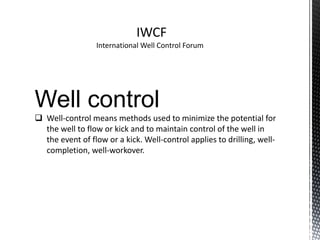
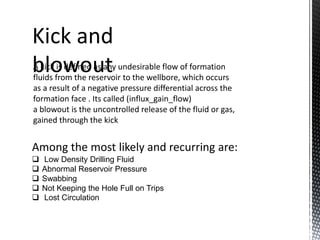
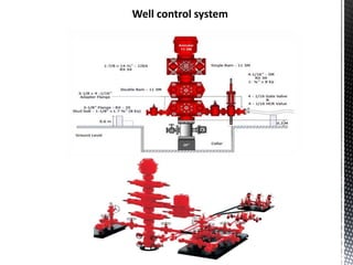
Well control
 Well-control means methods used to minimize the potential for
the well to flow or kick and to maintain control of the well in
the event of flow or a kick. Well-control applies to drilling, well-
completion, well-workover.
IWCF
International Well Control Forum
Kick and
blowout
A kick is defined as any undesirable flow of formation
fluids from the reservoir to the wellbore, which occurs
as a result of a negative pressure differential across the
formation face . Its called (influx_gain_flow)
a blowout is the uncontrolled release of the fluid or gas,
gained through the kick
Among the most likely and recurring are:
 Low Density Drilling Fluid
 Abnormal Reservoir Pressure
 Swabbing
 Not Keeping the Hole Full on Trips
 Lost Circulation
1. Hydrostatic Pressure
All vertical columns of fluid exert hydrostatic pressure.
HP = MW x 0.052 x TVD
2. Formation pressure
is the pressure contained inside the rock pore spaces.
3. Fracture pressure
is the amount of borehole pressure that it takes to split
or fail a formation and it can find it by (leak off test)
Bottomhole Pressure
Bottomhole pressure is equal to the sum of all pressures acting in a
well.
BHP= HP + SP + APL
o Bottomhole pressure at static (Pump off )
BHP=HP
o Bottomhole pressure at dynamic (Pump on)
BHP=HP+APL
Equivalent Circulating Density (ECD)
ECD=
𝑨𝑷𝑳
𝟎.𝟎𝟓𝟐∗𝑻𝑽𝑫
+MW
Swab and Surge Pressures
 Swab pressure is the temporary
reduction in the bottomhole
pressure that results from the
upward movement of pipe in the
hole.
 Surge pressure is the opposite
effect,
whereby wellbore pressure is
temporarily increased as pipe is
run into the well.
Warning signs of kicks
1. Flow rate increase
2 . Pit volume increase
3. Flowing well with pumps off
4. Pump pressure decrease and pump stroke increase
5 . Improper hole fill - up on trips
6 . String weight change
7. Drilling break
8. Cut mud weight
9.Increased penetration rate
Flow check procedure
At the first indication of a kick
1. Stop drilling
2. Raise the bit off the bottom of the well ( to shut in the well )
3. Stop the pumps and check to see if there is a flow from the well
4. If the well does flow , close the BOP and shut in the well
5. Readings are taken to stabilize shut in drill pipe and casing pressures
6. Calculation are made to determine the density of the mud that will
be used to kill the well
7. Calculations are also made to determine the kick out , and to fill the
hole with new mud
If well flow confirmed , the well should be
closed in quickly after a kick has been detected
in order to : Or reasons for shutting in the well
.
a . Minimize the size of the influx into the wellbore .
b . Minimize the SICP .
c . Minimize the casing shoe pressure
d . Minimize chances of losses
The difference between the formation
pressure at the bottom of the well and the
hydrostatic pressure in the drillpipe.
Recorded when a well is shut in on a kick.
From the SIDPP, one can calculate the
increase in mud weight needed to kill the well.
1-Shut-in drillpipe pressure (SIDPP)
Shut-in pipe pressure
2-The shut-in casing pressure (SICP)
is a measure of the difference between the
formation pressure and the HSP in the
annulus when a kick occurs.
Well control system
Type of shut in well
1-Soft shut in mathod:
the choke line valves are opened to allow the well to flow through
the surface choke. After the preventers are sealed, the choke is
then closed to stop the flow. The ‘soft shut-in’ procedure gives the
well additional time to flow before shut-in
2-hard shut in mathod:the choke line valves on the drilling
spool are in the closed position while drilling and remain closed
until after the preventer is sealed and well shut-in.
1. Shut-in Procedure while Drilling
 SPACE OUT Pick up drill string and spot tool joint.
 SHUT DOWN Stop the mud pumps.
 SHUT IN Close the annular preventer or uppermost
pipe ram preventer. Confirm that the well is shut in
and flow has stopped. Open HCR valve.
2. Shut-In Procedure while Tripping
 Stab valve Install Full-Open Safety Valve (open position)
in drill string.Close Safety Valve.
 space out Spot tool joint.
 shut-in Close the annular preventer or uppermost pipe
ram preventer. Confirm that the well is shut-in and flow has
stopped. Open HCR valve.
Kill Weight Mud or Kill Drilling Fluid Density is the mud weight required to
balance formation pressure. The kill weight mud may be pumped into the well
at different time depending on kill methods (Driller’s method, Wait and
Weight)
Kill Weight Mud (KWM) = Current Mud Weight + (
SIDPP
0.052∗TVD
)
Kill mud
Driller’s mathod
 FIRST CIRCULATION
1. taken slow circulating rate pressure then calculate the pressure required on the Drill Pipe for
the first circulation of the well. (ICP = SCR + SIDPP)
2. Open the choke about one quarter, start the pump and break circulation; then bring the
pump up to the KILL RATE.
3. While the Driller is bringing the mud pump up to the KILL RATE, the choke operator should
operate the choke so as to keep the casing pressure at or near the SICP reading.
4. Once the pump is up to the KILL RATE, the choke operator should transfer his attention to the
Drill Pipe pressure gauge and adjust the choke to maintain the ICP on the drill pipe pressure
gauge.
5. The last step on well control driller’s method is helding the the ICP constant on the Drill Pipe
pressure gauge by adjusting the choke throughout the whole of the first circulation, until all
of the Kick fluid has been circulated out of the well. The pump rate must also be held
constant at the KILL RATE throughout this period.
6. Once the Kick is out of the hole, Shut the well in and mix up the kill mud weight required.
 Second Circulation
7. Once the Kill mud is ready, open the choke about one quarter, start the pump and break
circulation. Then bring the pump up to the Kill rate.
8. While the Driller is bringing the pump up to the Kill rate, the choke operator should operate
the choke so as to keep the casing pressure steady at the same pressure as when closed in.
9. While the Drill Pipe is being filled with heavy mud there are two options for keeping B.H.P.
constant, either keep the casing pressure constant or make out a graph going from I.C.P. to
F.C.P.
well control (IWCF)

well control (IWCF)

  • 2.
    Well control  Well-controlmeans methods used to minimize the potential for the well to flow or kick and to maintain control of the well in the event of flow or a kick. Well-control applies to drilling, well- completion, well-workover. IWCF International Well Control Forum
  • 3.
    Kick and blowout A kickis defined as any undesirable flow of formation fluids from the reservoir to the wellbore, which occurs as a result of a negative pressure differential across the formation face . Its called (influx_gain_flow) a blowout is the uncontrolled release of the fluid or gas, gained through the kick Among the most likely and recurring are:  Low Density Drilling Fluid  Abnormal Reservoir Pressure  Swabbing  Not Keeping the Hole Full on Trips  Lost Circulation
  • 4.
    1. Hydrostatic Pressure Allvertical columns of fluid exert hydrostatic pressure. HP = MW x 0.052 x TVD 2. Formation pressure is the pressure contained inside the rock pore spaces. 3. Fracture pressure is the amount of borehole pressure that it takes to split or fail a formation and it can find it by (leak off test)
  • 5.
    Bottomhole Pressure Bottomhole pressureis equal to the sum of all pressures acting in a well. BHP= HP + SP + APL o Bottomhole pressure at static (Pump off ) BHP=HP o Bottomhole pressure at dynamic (Pump on) BHP=HP+APL Equivalent Circulating Density (ECD) ECD= 𝑨𝑷𝑳 𝟎.𝟎𝟓𝟐∗𝑻𝑽𝑫 +MW
  • 6.
    Swab and SurgePressures  Swab pressure is the temporary reduction in the bottomhole pressure that results from the upward movement of pipe in the hole.  Surge pressure is the opposite effect, whereby wellbore pressure is temporarily increased as pipe is run into the well.
  • 7.
    Warning signs ofkicks 1. Flow rate increase 2 . Pit volume increase 3. Flowing well with pumps off 4. Pump pressure decrease and pump stroke increase 5 . Improper hole fill - up on trips 6 . String weight change 7. Drilling break 8. Cut mud weight 9.Increased penetration rate
  • 8.
    Flow check procedure Atthe first indication of a kick 1. Stop drilling 2. Raise the bit off the bottom of the well ( to shut in the well ) 3. Stop the pumps and check to see if there is a flow from the well 4. If the well does flow , close the BOP and shut in the well 5. Readings are taken to stabilize shut in drill pipe and casing pressures 6. Calculation are made to determine the density of the mud that will be used to kill the well 7. Calculations are also made to determine the kick out , and to fill the hole with new mud
  • 9.
    If well flowconfirmed , the well should be closed in quickly after a kick has been detected in order to : Or reasons for shutting in the well . a . Minimize the size of the influx into the wellbore . b . Minimize the SICP . c . Minimize the casing shoe pressure d . Minimize chances of losses
  • 10.
    The difference betweenthe formation pressure at the bottom of the well and the hydrostatic pressure in the drillpipe. Recorded when a well is shut in on a kick. From the SIDPP, one can calculate the increase in mud weight needed to kill the well. 1-Shut-in drillpipe pressure (SIDPP) Shut-in pipe pressure 2-The shut-in casing pressure (SICP) is a measure of the difference between the formation pressure and the HSP in the annulus when a kick occurs.
  • 11.
  • 12.
    Type of shutin well 1-Soft shut in mathod: the choke line valves are opened to allow the well to flow through the surface choke. After the preventers are sealed, the choke is then closed to stop the flow. The ‘soft shut-in’ procedure gives the well additional time to flow before shut-in 2-hard shut in mathod:the choke line valves on the drilling spool are in the closed position while drilling and remain closed until after the preventer is sealed and well shut-in.
  • 13.
    1. Shut-in Procedurewhile Drilling  SPACE OUT Pick up drill string and spot tool joint.  SHUT DOWN Stop the mud pumps.  SHUT IN Close the annular preventer or uppermost pipe ram preventer. Confirm that the well is shut in and flow has stopped. Open HCR valve. 2. Shut-In Procedure while Tripping  Stab valve Install Full-Open Safety Valve (open position) in drill string.Close Safety Valve.  space out Spot tool joint.  shut-in Close the annular preventer or uppermost pipe ram preventer. Confirm that the well is shut-in and flow has stopped. Open HCR valve.
  • 14.
    Kill Weight Mudor Kill Drilling Fluid Density is the mud weight required to balance formation pressure. The kill weight mud may be pumped into the well at different time depending on kill methods (Driller’s method, Wait and Weight) Kill Weight Mud (KWM) = Current Mud Weight + ( SIDPP 0.052∗TVD ) Kill mud
  • 15.
    Driller’s mathod  FIRSTCIRCULATION 1. taken slow circulating rate pressure then calculate the pressure required on the Drill Pipe for the first circulation of the well. (ICP = SCR + SIDPP) 2. Open the choke about one quarter, start the pump and break circulation; then bring the pump up to the KILL RATE. 3. While the Driller is bringing the mud pump up to the KILL RATE, the choke operator should operate the choke so as to keep the casing pressure at or near the SICP reading. 4. Once the pump is up to the KILL RATE, the choke operator should transfer his attention to the Drill Pipe pressure gauge and adjust the choke to maintain the ICP on the drill pipe pressure gauge. 5. The last step on well control driller’s method is helding the the ICP constant on the Drill Pipe pressure gauge by adjusting the choke throughout the whole of the first circulation, until all of the Kick fluid has been circulated out of the well. The pump rate must also be held constant at the KILL RATE throughout this period. 6. Once the Kick is out of the hole, Shut the well in and mix up the kill mud weight required.  Second Circulation 7. Once the Kill mud is ready, open the choke about one quarter, start the pump and break circulation. Then bring the pump up to the Kill rate. 8. While the Driller is bringing the pump up to the Kill rate, the choke operator should operate the choke so as to keep the casing pressure steady at the same pressure as when closed in. 9. While the Drill Pipe is being filled with heavy mud there are two options for keeping B.H.P. constant, either keep the casing pressure constant or make out a graph going from I.C.P. to F.C.P.