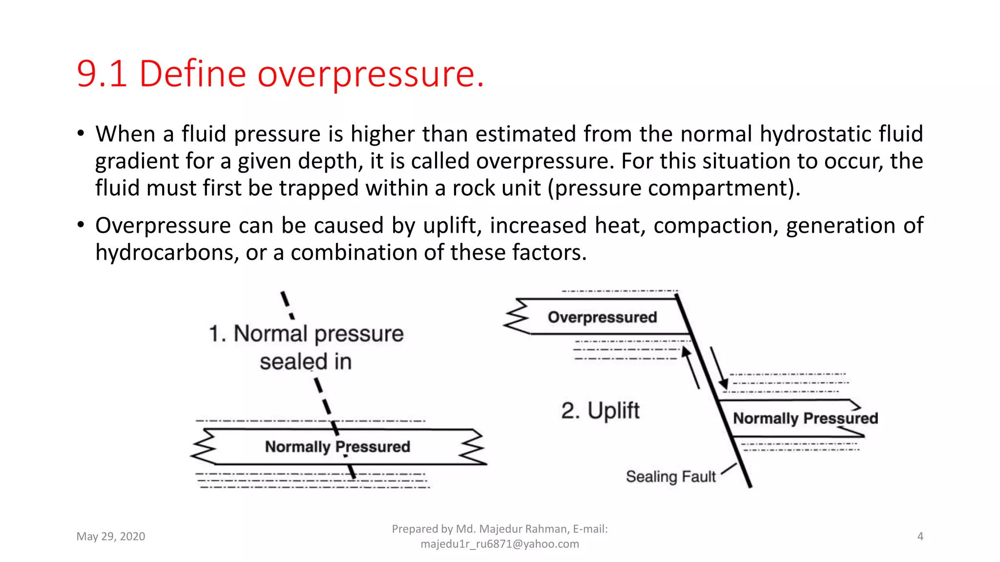
WELCOME TO THE STUDENTS
7th Semester (Mining)
Bogura Polytechnic Institute, Bogura.
Md. Majedur Rahman
B. Sc (Hon’s), M. Sc in Geology & Mining, RU
Instructor (Tech)
Mining and Mine Survey Technology
Bogura Polytechnic Institute, BOGURA.
Presented By
Prepared by Md. Majedur Rahman, E-mail: majedu1r_ru6871@yahoo.comMay 29, 2020 1
Petroleum Well Design & Completion
Course Code No. 69372
Prepared by Md. Majedur Rahman, E-mail:
majedu1r_ru6871@yahoo.com
May 29, 2020 2
Chapter-09
Understand well control and Blowout preventions
9.1 Define overpressure.
9.2 Define and mention the causes of well kick.
9.3 Explain Causes of Blowout.
9.4 Describe Blowout prevention techniques
9.5 Describe well control hazards
9.6 Describe well shutdown process.
9.7 Explain the fishing operation.
Prepared by Md. Majedur Rahman, E-mail:
majedu1r_ru6871@yahoo.com
May 29, 2020 3
• When a fluid pressure is higher than estimated from the normal hydrostatic fluid
gradient for a given depth, it is called overpressure. For this situation to occur, the
fluid must first be trapped within a rock unit (pressure compartment).
• Overpressure can be caused by uplift, increased heat, compaction, generation of
hydrocarbons, or a combination of these factors.
May 29, 2020
Prepared by Md. Majedur Rahman, E-mail:
majedu1r_ru6871@yahoo.com
4
9.1 Define overpressure.
9.2 Define and mention the causes of well kick.
A kick is a well control problem in which the pressure found within the
drilled rock is higher than the mud hydrostatic pressure acting on the
borehole or rock face. When this occurs, the greater formation pressure has
a tendency to force formation fluids into the wellbore. This forced fluid flow
is called a kick.
Kicks occur as a result of formation pressure being greater than mud
hydrostatic pressure, which causes fluids to flow from the formation into the
wellbore. In almost all drilling operations, the operator attempts to maintain
a hydrostatic pressure greater than formation pressure and, thus, prevent
kicks; however, on occasion the formation will exceed the mud pressure and
a kick will occur.
May 29, 2020
Prepared by Md. Majedur Rahman, E-mail:
majedu1r_ru6871@yahoo.com
5
Reasons for this imbalance explain the key causes of kicks:
• Insufficient mud weight.
• Improper hole fill-up during trips.
• Swabbing.
• Cut mud.
• Lost circulation.
May 29, 2020
Prepared by Md. Majedur Rahman, E-mail:
majedu1r_ru6871@yahoo.com
6
Warning signs of kicks
Warning signs and possible kick indicators can be observed at the surface.
Each crew member has the responsibility to recognize and interpret these
signs and take proper action. All signs do not positively identify a kick; some
merely warn of potential kick situations. Key warning signs to watch for
include the following:
• Flow rate increase
• Pit volume increase
• Flowing well with pumps off
• Pump pressure decrease and pump stroke increase
• Improper hole fill-up on trips
• String weight change
• Drilling break
• Cut mud weight
May 29, 2020
Prepared by Md. Majedur Rahman, E-mail:
majedu1r_ru6871@yahoo.com
7
Each is identified below as a primary or secondary warning sign,
relative to its importance in kick detection.
• Flow rate increase (primary indicator)
• Pit volume increase (primary indicator)
• Flowing well with pumps off (primary indicator)
• Pump pressure decrease and pump stroke increase (secondary indicator)
• Improper hole fill-up on trips (primary indicator)
• String weight change (secondary indicator)
• Drilling break (secondary indicator)
• Cut mud weight (secondary indicator)
May 29, 2020
Prepared by Md. Majedur Rahman, E-mail:
majedu1r_ru6871@yahoo.com
8
9.3 Explain Causes of Blowout.
A blowout is the uncontrolled release of crude oil and/or natural
gas from an oil well or gas well after pressure control systems
have failed. Modern wells have blowout preventers intended to
prevent such an occurrence. An accidental spark during
a blowout can lead to a catastrophic oil or gas fire.
May 29, 2020
Prepared by Md. Majedur Rahman, E-mail:
majedu1r_ru6871@yahoo.com
9
Good planning, execution, and analysis will reduce frequency and severity of kicks, while a
true commitment to understanding kicks will eliminate loss of wells resulting from
blowouts and stuck pipe. Nevertheless, kicks can occur in any drilling operation conducted
with a view towards attaining maximum effectiveness, These relatively infrequent kicks
need not be unduly dangerous nor time-consuming when proper and prompt action is
taken.
• Pressure unbalance leading to a kick may result from one or more of the following
causes:
• Poor well planning;
• Failure to keep the hole full;
• Swabbing;
• Lost circulation;
• Mud weight too low.
• A blowout is an uncontrolled kick. Kicks develop into blowouts for one or more of the
following reasons:
• Lack of early detection;
• Failure to take proper initial action;
• Lack of adequate casing and/or control equipment;
• Malfunction of control equipment.
May 29, 2020
Prepared by Md. Majedur Rahman, E-mail:
majedu1r_ru6871@yahoo.com
10
Types of Blowouts
• There are three main types of blowouts, all of which can occur at any point of the
drilling process and can have disastrous consequences. These are:
• Surface Blowouts. The most common type of blowouts, these are at risk of
damaging the rig and surrounding terrain, as well as the even more serious risk of
ignition and explosion. If a surface blowout is particularly forceful, it cannot be
controlled alone; and so, other nearby wells (known as “relief wells”) will be
drilled to introduce heavier balancing fluid at depth.
• Underground Blowouts. These are uncommon blowouts where fluid from deep,
high-pressurised formations flow upwards, unchecked, to shallow, low-
pressurised formations. This may not necessarily result in the release of oil above
ground.
• Underwater Blowouts. Due to their location, these are the hardest blowouts to
deal with. The biggest and deepest underwater blowout in history occurred in
2010 at the Deepwater Horizon well in the Gulf of Mexico. The accident was so
serious that it forced the industry to contemplate re-evaluating its safety
procedures,
May 29, 2020
Prepared by Md. Majedur Rahman, E-mail:
majedu1r_ru6871@yahoo.com
11
9.4 Describe Blowout prevention techniques
The Well Control System or the Blowout Prevention System on a drilling rig is
the system that prevents the uncontrolled, catastrophic release of high-
pressure fluids (oil, gas, or salt water) from subsurface formations. These
uncontrolled releases of formation fluids are referred to as Blowouts.
Well kicks are prevented by maintaining the hydrostatic pressure of the drilling fluid
greater than the formation pressures that are exposed to the wellbore. Since
hydrostatic pressure is determined by the density (weight) and the true vertical
height of the drilling fluid column, the primary responsibilities of the drilling crews
in preventing well kicks are as follows:
• Maintain the mud weight specified by the operator/mud company.
• Keep the hole full of mud at all times.
May 29, 2020
Prepared by Md. Majedur Rahman, E-mail:
majedu1r_ru6871@yahoo.com
12
BLOWOUT PREVENTERS
(BOP)
 If the formation pressure is
more than the imposed by
drilling fluid, in this case
formation fluids flow into
borehole and eventually to the
surface.
 This effect is called blowout.
 The main function of blowout
preventers is to close the
annular space between the drill
pipe and casing.
Well Control System
COMMITMENT TO ACADEMIC AND INDUSTRIAL EXCELLENCE 13
When wells are drilled on land or in very shallow water where the wellhead is
above the water line, BOPs are activated by hydraulic pressure from a remote
accumulator. Several control stations will be mounted around the rig. They also can
be closed manually by turning large wheel-like handles.
In deeper offshore operations with the wellhead just above the mudline on the sea
floor, there are five primary ways by which a BOP can be controlled. The possible
means are:
• Hydraulic Control Signal: sent from surface through a hydraulic umbilical;
• Electrical Control Signal: sent from the surface through a control cable;
• Acoustical Control Signal: sent from the surface based on a modulated/encoded
pulse of sound transmitted by an underwater transducer;
• ROV Intervention: remotely operated vehicles (ROVs) mechanically control valves
and provide hydraulic pressure to the stack (via “hot stab” panels);
• Deadman Switch / Auto Shear: fail-safe activation of selected BOPs during an
emergency, and if the control, power and hydraulic lines have been severed.
May 29, 2020
Prepared by Md. Majedur Rahman, E-mail:
majedu1r_ru6871@yahoo.com
14
9.5 Describe well control hazards
A drilling hazard is defined as any eventoff of the critical path of drilling
operations. Using a DHM approach early in the well planning process is
essential to its effectiveness and success. DHM focuses on wellbore
stability and consequential hazards such as stuck pipe, fluids loss,and
equivalent circulating density(ECD) management. These events lead to
non-productive drilling time in the least case or catastrophic wellbore
failure and jeopardize well control in the worst cases. DHMrequires
understanding the uncertainty of the drilling margin—the safe applied
ECD between the in-situ pore pressure and/or stress equivalence and
the fracture gradient as a result of the overburden at true vertical
depth(TVD). Because all drilling operations have risk, mitigating these
risks is fundamental to DHM
May 29, 2020
Prepared by Md. Majedur Rahman, E-mail:
majedu1r_ru6871@yahoo.com
15
A well kill procedure is an oil well control method. Once the well has
been shut-in on a kick, proper kill procedures must be done
immediately. The general idea in well kill procedure is to circulate out
any formation fluid already in the wellbore during kick, and then
circulate a satisfactory weight of kill mud called Kill Weight Mud (KWM)
into the well without allowing further fluid into the hole. If this can be
done, then once the kill mud has been fully circulated around the well,
it is possible to open up the well and restart normal operations.
Generally, a kill weight mud (KWM) mix, which provides just hydrostatic
balance for formation pressure, is circulated. This allows approximately
constant bottom hole pressure, which is slightly greater than formation
pressure to be maintained, as the kill circulation proceeds because of
the additional small circulating friction pressure loss. After circulation,
the well is opened up again.
May 29, 2020
Prepared by Md. Majedur Rahman, E-mail:
majedu1r_ru6871@yahoo.com
16
The major well kill procedures used in oil well control are listed below:
• Wait and Weight
• Driller method
• Circulate and Weight
• Concurrent Method
• Reverse Circulation
• Dynamic Kill procedure
• Bull heading
• Volumetric Method
• Lubricate and Bleed
May 29, 2020
Prepared by Md. Majedur Rahman, E-mail:
majedu1r_ru6871@yahoo.com
17
9.6 Describe well shutdown process.
• Also called well decomissioning.
• Decommissioning of offshore installations came to international
prominence as a result of Shell's proposals to dispose of the
Brent Spar oil storage tank by dumping it in deep water beyond
the edge of the Continental Shelf.
May 29, 2020
Prepared by Md. Majedur Rahman, E-mail:
majedu1r_ru6871@yahoo.com
18
• Using shut-in procedures is one of the oil-well-control measures to curtail
kicks and prevent a blowout from occurring. Shut-in procedures are
specific procedures for closing a well in case of a kick. When any positive
indication of a kick is observed, such as a sudden increase in flow, or an
increase in pit level, then the well should be shut-in immediately. If a well
shut-in is not done promptly, a blowout is likely to happen.
• Shut-in procedures are usually developed and practiced for every rig
activity, such as drilling, tripping, logging, running tubular, performing a
drill stem test, and so on. The primary purpose of a specific shut-in
procedure is to minimize kick volume entering into a wellbore when a kick
occurs, regardless of what phase of rig activity is occurring. However, a
shut-in procedure is a company-specific procedure, and the policy of a
company will dictate how a well should be shut-in.
• They are generally two type of Shut-in procedures which are soft shut-in or
hard shut-in. Of these two methods, the hard shut-in is the fastest method
to shut in the well; therefore, it will minimize the volume of kick allowed
into the wellbore.
May 29, 2020
Prepared by Md. Majedur Rahman, E-mail:
majedu1r_ru6871@yahoo.com
19
9.7 Explain the fishing operation.
In technical terms, a fish can be any object which has been lost or stuck
in a borehole, and has a serious negative impact on well operations.
Fishes can be anything, whether that is a drill string that has come
away, a bit cone, or even a hand tool that has been inadvertently
dropped into the well. To solve this issue, fishing involves the use of
special tools and procedures to recover the fish and allow drilling to
continue. While this article will deal solely with regular fishing, there is
also an alternative method, which involves using through-tubing
processes that make use of tools on a wireline or coiled tubing.
May 29, 2020
Prepared by Md. Majedur Rahman, E-mail:
majedu1r_ru6871@yahoo.com
20
Virtually any object that is dropped into a well, or even run into it, may need to be
fished out at some point. Furthermore, the need for fishing may arise at any given
point during operations, and there are therefore a wide range of different tools and
methods. There are three main technologies that these solutions are built around,
though: pulling, milling, or cutting the pipe itself, and other downhole parts.
A fishing job is one option, but this will depend on the cost and likelihood of
success. Other options include:
• Leaving the fish where it is, and sidetracking or redrilling the well to follow an
alternative path
• Leaving the fish where it is, and completing the well in a shallower zone
• Abandoning the well altogether
Preferably, the fish should be completely avoided in the first place, thanks to the
right planning and proper drilling practices. However, it is important that a
contingency plan is in place should the situation arise.
May 29, 2020
Prepared by Md. Majedur Rahman, E-mail:
majedu1r_ru6871@yahoo.com
21
Although many different objects can get lost or stuck in a wellbore, fish
can be divided into a few major categories.
• Stuck pipe
• Parted Pipe
• Junk
• Cable and Wireline Tools
May 29, 2020
Prepared by Md. Majedur Rahman, E-mail:
majedu1r_ru6871@yahoo.com
22
Fishing Challenges
In most situations, it is relatively simple to diagnose and resolve a
fishing situation. For instance, should a bit torque up, and it is found
that a cone is missing, then it will be clear that junk has been left inside
the well. Alternatively, by looking at the recovered portion of a parted
drill string, it is possible to calculate where the parting happened, and
what caused it. These calculations allow for the right fishing tool
assembly to be constructed, and for the rest of the string to be
recovered.
May 29, 2020
Prepared by Md. Majedur Rahman, E-mail:
majedu1r_ru6871@yahoo.com
23
Planning and Preparation for Fishing Operation
By planning out the well carefully, and adhering to proper drilling practices, the need for
fishing can be avoided in most cases. However, it’s impossible to completely eliminate the
risk of fishing jobs. By assuming that something will eventually go wrong, drilling
companies can be prepared for any eventuality.
To make the fishing job easier, it is vital that you have access to all relevant records of
equipment in the well. Your records will need to contain the following information:
• A tally of your current drill pipe, including its weight, grade and tool joint specifications
• Information on the ensile strength of the pipe, as well as the rig’s hoisting capacity. This
must include the maximum pull that the pipe can take based on these limitations, as well
as necessary safety factors
• In-depth plans of the bottomhole assembly, with each tool’s length, inside and outside
diameters, and rotary connections listed
• If you are using logging or surveying equipment, then you’ll need the dimensions of each
tool used, along with the diameter and strength of the wireline
• A complete casing record, including all casing depths, diameters, weights and grades,
perforation depths, liner tops and any other relevant information
• Up-to-date mud reports
May 29, 2020
Prepared by Md. Majedur Rahman, E-mail:
majedu1r_ru6871@yahoo.com
24
Any Questions
Prepared by Md. Majedur Rahman, E-mail:
majedu1r_ru6871@yahoo.com
May 29, 2020 25
THANKS TO ALL
Prepared by Md. Majedur Rahman, E-mail:
majedu1r_ru6871@yahoo.com
May 29, 2020 26

Well control and blowout preventions

  • 1.
    WELCOME TO THESTUDENTS 7th Semester (Mining) Bogura Polytechnic Institute, Bogura. Md. Majedur Rahman B. Sc (Hon’s), M. Sc in Geology & Mining, RU Instructor (Tech) Mining and Mine Survey Technology Bogura Polytechnic Institute, BOGURA. Presented By Prepared by Md. Majedur Rahman, E-mail: majedu1r_ru6871@yahoo.comMay 29, 2020 1
  • 2.
    Petroleum Well Design& Completion Course Code No. 69372 Prepared by Md. Majedur Rahman, E-mail: majedu1r_ru6871@yahoo.com May 29, 2020 2
  • 3.
    Chapter-09 Understand well controland Blowout preventions 9.1 Define overpressure. 9.2 Define and mention the causes of well kick. 9.3 Explain Causes of Blowout. 9.4 Describe Blowout prevention techniques 9.5 Describe well control hazards 9.6 Describe well shutdown process. 9.7 Explain the fishing operation. Prepared by Md. Majedur Rahman, E-mail: majedu1r_ru6871@yahoo.com May 29, 2020 3
  • 4.
    • When afluid pressure is higher than estimated from the normal hydrostatic fluid gradient for a given depth, it is called overpressure. For this situation to occur, the fluid must first be trapped within a rock unit (pressure compartment). • Overpressure can be caused by uplift, increased heat, compaction, generation of hydrocarbons, or a combination of these factors. May 29, 2020 Prepared by Md. Majedur Rahman, E-mail: majedu1r_ru6871@yahoo.com 4 9.1 Define overpressure.
  • 5.
    9.2 Define andmention the causes of well kick. A kick is a well control problem in which the pressure found within the drilled rock is higher than the mud hydrostatic pressure acting on the borehole or rock face. When this occurs, the greater formation pressure has a tendency to force formation fluids into the wellbore. This forced fluid flow is called a kick. Kicks occur as a result of formation pressure being greater than mud hydrostatic pressure, which causes fluids to flow from the formation into the wellbore. In almost all drilling operations, the operator attempts to maintain a hydrostatic pressure greater than formation pressure and, thus, prevent kicks; however, on occasion the formation will exceed the mud pressure and a kick will occur. May 29, 2020 Prepared by Md. Majedur Rahman, E-mail: majedu1r_ru6871@yahoo.com 5
  • 6.
    Reasons for thisimbalance explain the key causes of kicks: • Insufficient mud weight. • Improper hole fill-up during trips. • Swabbing. • Cut mud. • Lost circulation. May 29, 2020 Prepared by Md. Majedur Rahman, E-mail: majedu1r_ru6871@yahoo.com 6
  • 7.
    Warning signs ofkicks Warning signs and possible kick indicators can be observed at the surface. Each crew member has the responsibility to recognize and interpret these signs and take proper action. All signs do not positively identify a kick; some merely warn of potential kick situations. Key warning signs to watch for include the following: • Flow rate increase • Pit volume increase • Flowing well with pumps off • Pump pressure decrease and pump stroke increase • Improper hole fill-up on trips • String weight change • Drilling break • Cut mud weight May 29, 2020 Prepared by Md. Majedur Rahman, E-mail: majedu1r_ru6871@yahoo.com 7
  • 8.
    Each is identifiedbelow as a primary or secondary warning sign, relative to its importance in kick detection. • Flow rate increase (primary indicator) • Pit volume increase (primary indicator) • Flowing well with pumps off (primary indicator) • Pump pressure decrease and pump stroke increase (secondary indicator) • Improper hole fill-up on trips (primary indicator) • String weight change (secondary indicator) • Drilling break (secondary indicator) • Cut mud weight (secondary indicator) May 29, 2020 Prepared by Md. Majedur Rahman, E-mail: majedu1r_ru6871@yahoo.com 8
  • 9.
    9.3 Explain Causesof Blowout. A blowout is the uncontrolled release of crude oil and/or natural gas from an oil well or gas well after pressure control systems have failed. Modern wells have blowout preventers intended to prevent such an occurrence. An accidental spark during a blowout can lead to a catastrophic oil or gas fire. May 29, 2020 Prepared by Md. Majedur Rahman, E-mail: majedu1r_ru6871@yahoo.com 9
  • 10.
    Good planning, execution,and analysis will reduce frequency and severity of kicks, while a true commitment to understanding kicks will eliminate loss of wells resulting from blowouts and stuck pipe. Nevertheless, kicks can occur in any drilling operation conducted with a view towards attaining maximum effectiveness, These relatively infrequent kicks need not be unduly dangerous nor time-consuming when proper and prompt action is taken. • Pressure unbalance leading to a kick may result from one or more of the following causes: • Poor well planning; • Failure to keep the hole full; • Swabbing; • Lost circulation; • Mud weight too low. • A blowout is an uncontrolled kick. Kicks develop into blowouts for one or more of the following reasons: • Lack of early detection; • Failure to take proper initial action; • Lack of adequate casing and/or control equipment; • Malfunction of control equipment. May 29, 2020 Prepared by Md. Majedur Rahman, E-mail: majedu1r_ru6871@yahoo.com 10
  • 11.
    Types of Blowouts •There are three main types of blowouts, all of which can occur at any point of the drilling process and can have disastrous consequences. These are: • Surface Blowouts. The most common type of blowouts, these are at risk of damaging the rig and surrounding terrain, as well as the even more serious risk of ignition and explosion. If a surface blowout is particularly forceful, it cannot be controlled alone; and so, other nearby wells (known as “relief wells”) will be drilled to introduce heavier balancing fluid at depth. • Underground Blowouts. These are uncommon blowouts where fluid from deep, high-pressurised formations flow upwards, unchecked, to shallow, low- pressurised formations. This may not necessarily result in the release of oil above ground. • Underwater Blowouts. Due to their location, these are the hardest blowouts to deal with. The biggest and deepest underwater blowout in history occurred in 2010 at the Deepwater Horizon well in the Gulf of Mexico. The accident was so serious that it forced the industry to contemplate re-evaluating its safety procedures, May 29, 2020 Prepared by Md. Majedur Rahman, E-mail: majedu1r_ru6871@yahoo.com 11
  • 12.
    9.4 Describe Blowoutprevention techniques The Well Control System or the Blowout Prevention System on a drilling rig is the system that prevents the uncontrolled, catastrophic release of high- pressure fluids (oil, gas, or salt water) from subsurface formations. These uncontrolled releases of formation fluids are referred to as Blowouts. Well kicks are prevented by maintaining the hydrostatic pressure of the drilling fluid greater than the formation pressures that are exposed to the wellbore. Since hydrostatic pressure is determined by the density (weight) and the true vertical height of the drilling fluid column, the primary responsibilities of the drilling crews in preventing well kicks are as follows: • Maintain the mud weight specified by the operator/mud company. • Keep the hole full of mud at all times. May 29, 2020 Prepared by Md. Majedur Rahman, E-mail: majedu1r_ru6871@yahoo.com 12
  • 13.
    BLOWOUT PREVENTERS (BOP)  Ifthe formation pressure is more than the imposed by drilling fluid, in this case formation fluids flow into borehole and eventually to the surface.  This effect is called blowout.  The main function of blowout preventers is to close the annular space between the drill pipe and casing. Well Control System COMMITMENT TO ACADEMIC AND INDUSTRIAL EXCELLENCE 13
  • 14.
    When wells aredrilled on land or in very shallow water where the wellhead is above the water line, BOPs are activated by hydraulic pressure from a remote accumulator. Several control stations will be mounted around the rig. They also can be closed manually by turning large wheel-like handles. In deeper offshore operations with the wellhead just above the mudline on the sea floor, there are five primary ways by which a BOP can be controlled. The possible means are: • Hydraulic Control Signal: sent from surface through a hydraulic umbilical; • Electrical Control Signal: sent from the surface through a control cable; • Acoustical Control Signal: sent from the surface based on a modulated/encoded pulse of sound transmitted by an underwater transducer; • ROV Intervention: remotely operated vehicles (ROVs) mechanically control valves and provide hydraulic pressure to the stack (via “hot stab” panels); • Deadman Switch / Auto Shear: fail-safe activation of selected BOPs during an emergency, and if the control, power and hydraulic lines have been severed. May 29, 2020 Prepared by Md. Majedur Rahman, E-mail: majedu1r_ru6871@yahoo.com 14
  • 15.
    9.5 Describe wellcontrol hazards A drilling hazard is defined as any eventoff of the critical path of drilling operations. Using a DHM approach early in the well planning process is essential to its effectiveness and success. DHM focuses on wellbore stability and consequential hazards such as stuck pipe, fluids loss,and equivalent circulating density(ECD) management. These events lead to non-productive drilling time in the least case or catastrophic wellbore failure and jeopardize well control in the worst cases. DHMrequires understanding the uncertainty of the drilling margin—the safe applied ECD between the in-situ pore pressure and/or stress equivalence and the fracture gradient as a result of the overburden at true vertical depth(TVD). Because all drilling operations have risk, mitigating these risks is fundamental to DHM May 29, 2020 Prepared by Md. Majedur Rahman, E-mail: majedu1r_ru6871@yahoo.com 15
  • 16.
    A well killprocedure is an oil well control method. Once the well has been shut-in on a kick, proper kill procedures must be done immediately. The general idea in well kill procedure is to circulate out any formation fluid already in the wellbore during kick, and then circulate a satisfactory weight of kill mud called Kill Weight Mud (KWM) into the well without allowing further fluid into the hole. If this can be done, then once the kill mud has been fully circulated around the well, it is possible to open up the well and restart normal operations. Generally, a kill weight mud (KWM) mix, which provides just hydrostatic balance for formation pressure, is circulated. This allows approximately constant bottom hole pressure, which is slightly greater than formation pressure to be maintained, as the kill circulation proceeds because of the additional small circulating friction pressure loss. After circulation, the well is opened up again. May 29, 2020 Prepared by Md. Majedur Rahman, E-mail: majedu1r_ru6871@yahoo.com 16
  • 17.
    The major wellkill procedures used in oil well control are listed below: • Wait and Weight • Driller method • Circulate and Weight • Concurrent Method • Reverse Circulation • Dynamic Kill procedure • Bull heading • Volumetric Method • Lubricate and Bleed May 29, 2020 Prepared by Md. Majedur Rahman, E-mail: majedu1r_ru6871@yahoo.com 17
  • 18.
    9.6 Describe wellshutdown process. • Also called well decomissioning. • Decommissioning of offshore installations came to international prominence as a result of Shell's proposals to dispose of the Brent Spar oil storage tank by dumping it in deep water beyond the edge of the Continental Shelf. May 29, 2020 Prepared by Md. Majedur Rahman, E-mail: majedu1r_ru6871@yahoo.com 18
  • 19.
    • Using shut-inprocedures is one of the oil-well-control measures to curtail kicks and prevent a blowout from occurring. Shut-in procedures are specific procedures for closing a well in case of a kick. When any positive indication of a kick is observed, such as a sudden increase in flow, or an increase in pit level, then the well should be shut-in immediately. If a well shut-in is not done promptly, a blowout is likely to happen. • Shut-in procedures are usually developed and practiced for every rig activity, such as drilling, tripping, logging, running tubular, performing a drill stem test, and so on. The primary purpose of a specific shut-in procedure is to minimize kick volume entering into a wellbore when a kick occurs, regardless of what phase of rig activity is occurring. However, a shut-in procedure is a company-specific procedure, and the policy of a company will dictate how a well should be shut-in. • They are generally two type of Shut-in procedures which are soft shut-in or hard shut-in. Of these two methods, the hard shut-in is the fastest method to shut in the well; therefore, it will minimize the volume of kick allowed into the wellbore. May 29, 2020 Prepared by Md. Majedur Rahman, E-mail: majedu1r_ru6871@yahoo.com 19
  • 20.
    9.7 Explain thefishing operation. In technical terms, a fish can be any object which has been lost or stuck in a borehole, and has a serious negative impact on well operations. Fishes can be anything, whether that is a drill string that has come away, a bit cone, or even a hand tool that has been inadvertently dropped into the well. To solve this issue, fishing involves the use of special tools and procedures to recover the fish and allow drilling to continue. While this article will deal solely with regular fishing, there is also an alternative method, which involves using through-tubing processes that make use of tools on a wireline or coiled tubing. May 29, 2020 Prepared by Md. Majedur Rahman, E-mail: majedu1r_ru6871@yahoo.com 20
  • 21.
    Virtually any objectthat is dropped into a well, or even run into it, may need to be fished out at some point. Furthermore, the need for fishing may arise at any given point during operations, and there are therefore a wide range of different tools and methods. There are three main technologies that these solutions are built around, though: pulling, milling, or cutting the pipe itself, and other downhole parts. A fishing job is one option, but this will depend on the cost and likelihood of success. Other options include: • Leaving the fish where it is, and sidetracking or redrilling the well to follow an alternative path • Leaving the fish where it is, and completing the well in a shallower zone • Abandoning the well altogether Preferably, the fish should be completely avoided in the first place, thanks to the right planning and proper drilling practices. However, it is important that a contingency plan is in place should the situation arise. May 29, 2020 Prepared by Md. Majedur Rahman, E-mail: majedu1r_ru6871@yahoo.com 21
  • 22.
    Although many differentobjects can get lost or stuck in a wellbore, fish can be divided into a few major categories. • Stuck pipe • Parted Pipe • Junk • Cable and Wireline Tools May 29, 2020 Prepared by Md. Majedur Rahman, E-mail: majedu1r_ru6871@yahoo.com 22
  • 23.
    Fishing Challenges In mostsituations, it is relatively simple to diagnose and resolve a fishing situation. For instance, should a bit torque up, and it is found that a cone is missing, then it will be clear that junk has been left inside the well. Alternatively, by looking at the recovered portion of a parted drill string, it is possible to calculate where the parting happened, and what caused it. These calculations allow for the right fishing tool assembly to be constructed, and for the rest of the string to be recovered. May 29, 2020 Prepared by Md. Majedur Rahman, E-mail: majedu1r_ru6871@yahoo.com 23
  • 24.
    Planning and Preparationfor Fishing Operation By planning out the well carefully, and adhering to proper drilling practices, the need for fishing can be avoided in most cases. However, it’s impossible to completely eliminate the risk of fishing jobs. By assuming that something will eventually go wrong, drilling companies can be prepared for any eventuality. To make the fishing job easier, it is vital that you have access to all relevant records of equipment in the well. Your records will need to contain the following information: • A tally of your current drill pipe, including its weight, grade and tool joint specifications • Information on the ensile strength of the pipe, as well as the rig’s hoisting capacity. This must include the maximum pull that the pipe can take based on these limitations, as well as necessary safety factors • In-depth plans of the bottomhole assembly, with each tool’s length, inside and outside diameters, and rotary connections listed • If you are using logging or surveying equipment, then you’ll need the dimensions of each tool used, along with the diameter and strength of the wireline • A complete casing record, including all casing depths, diameters, weights and grades, perforation depths, liner tops and any other relevant information • Up-to-date mud reports May 29, 2020 Prepared by Md. Majedur Rahman, E-mail: majedu1r_ru6871@yahoo.com 24
  • 25.
    Any Questions Prepared byMd. Majedur Rahman, E-mail: majedu1r_ru6871@yahoo.com May 29, 2020 25
  • 26.
    THANKS TO ALL Preparedby Md. Majedur Rahman, E-mail: majedu1r_ru6871@yahoo.com May 29, 2020 26