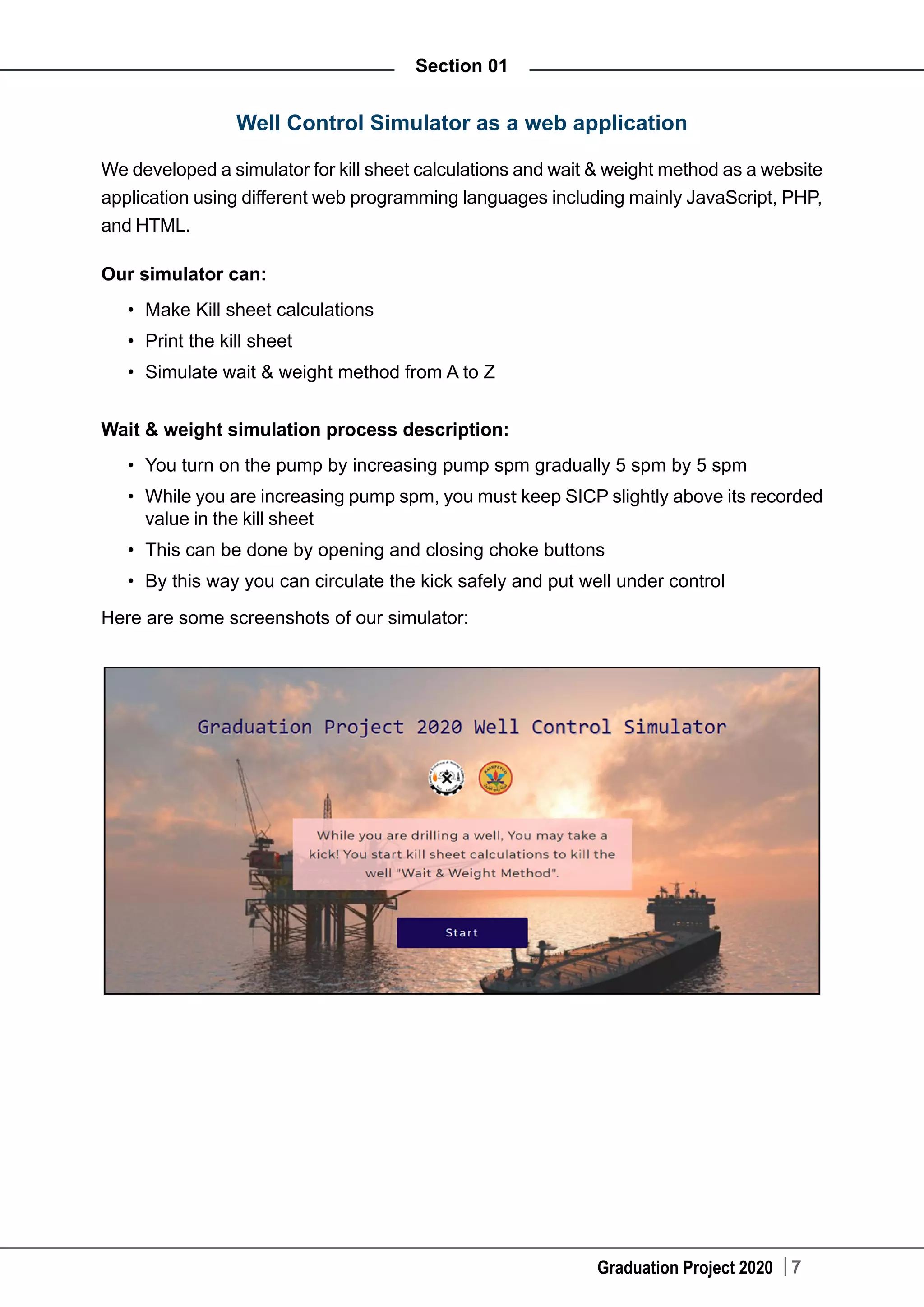
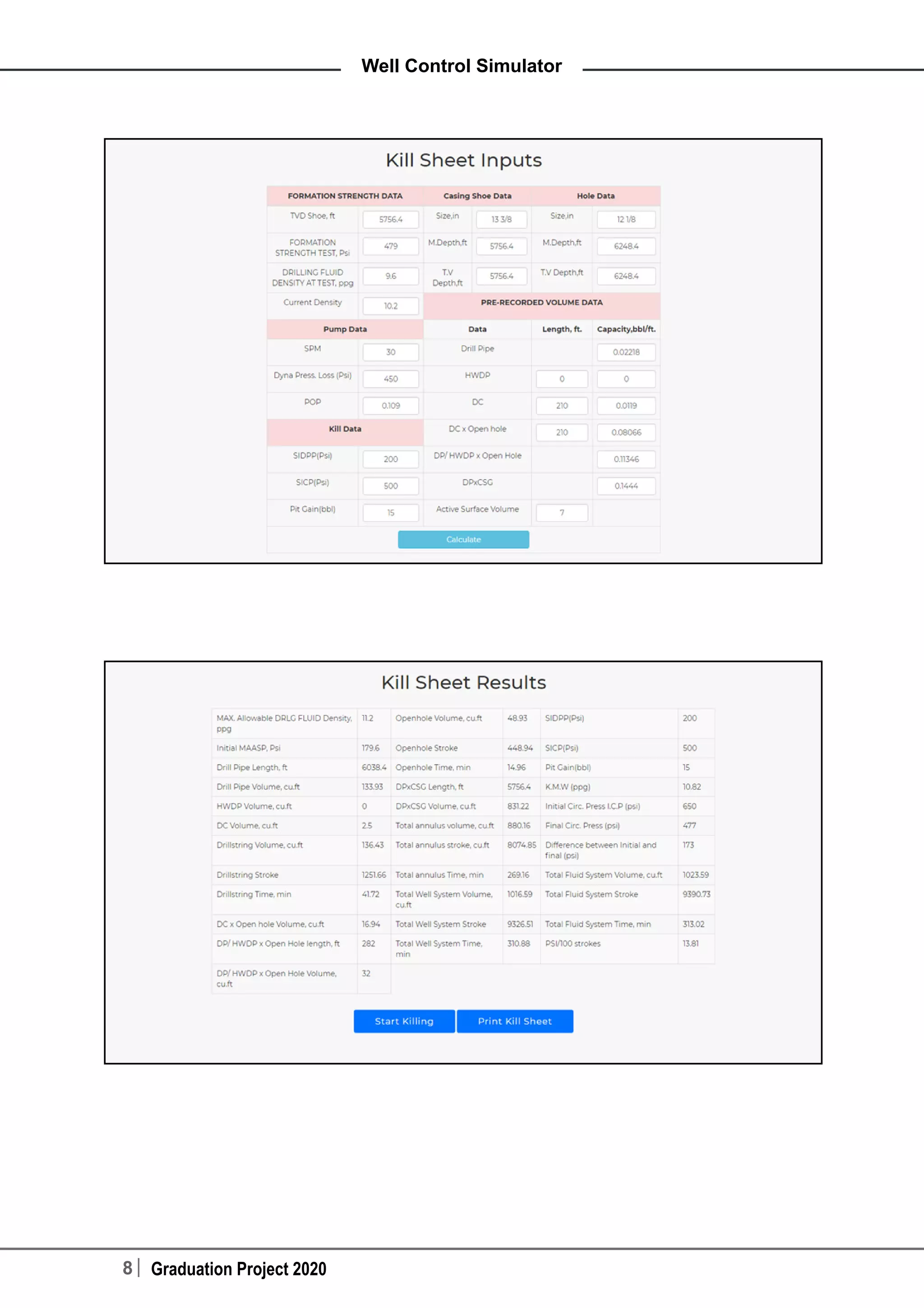
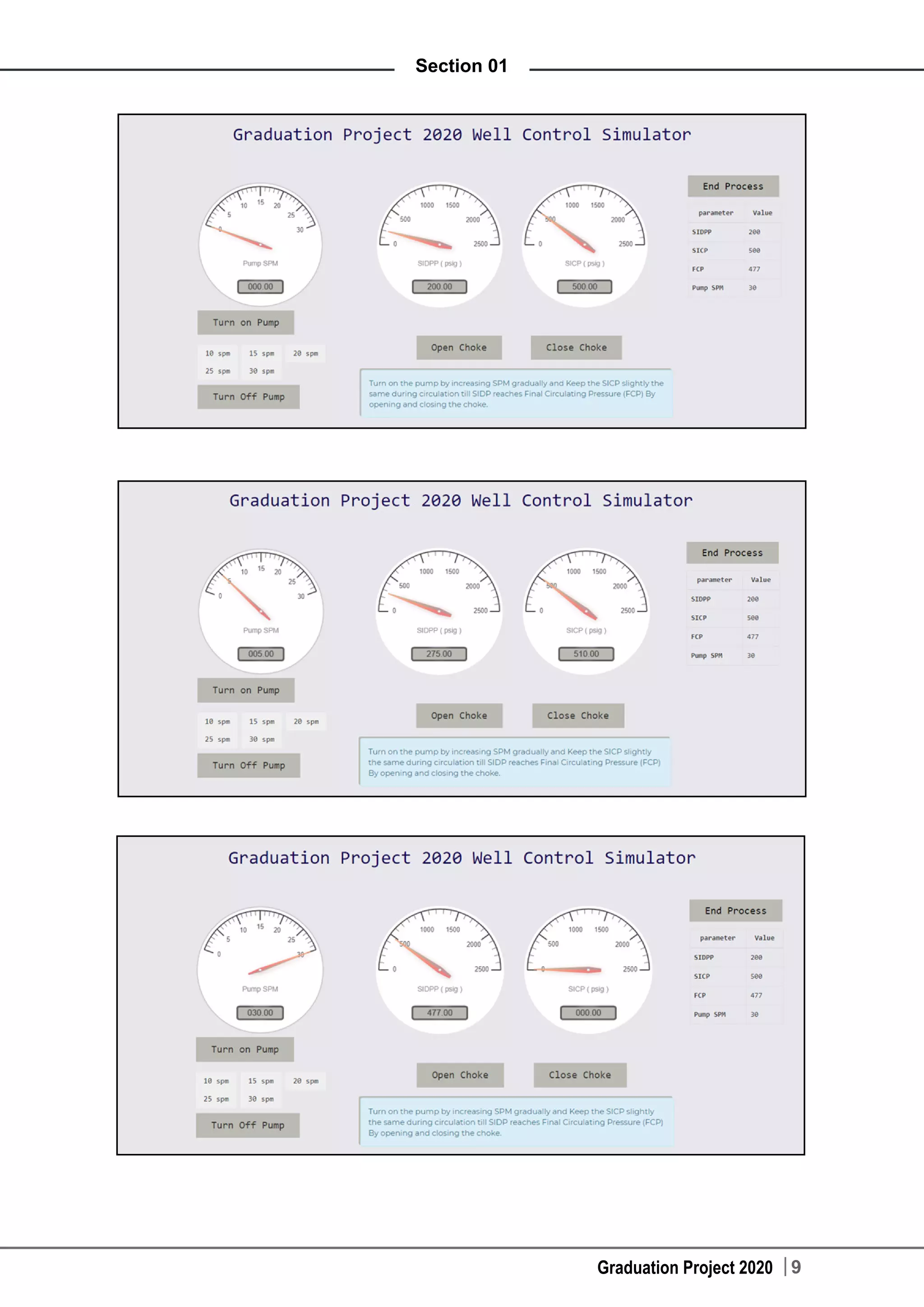
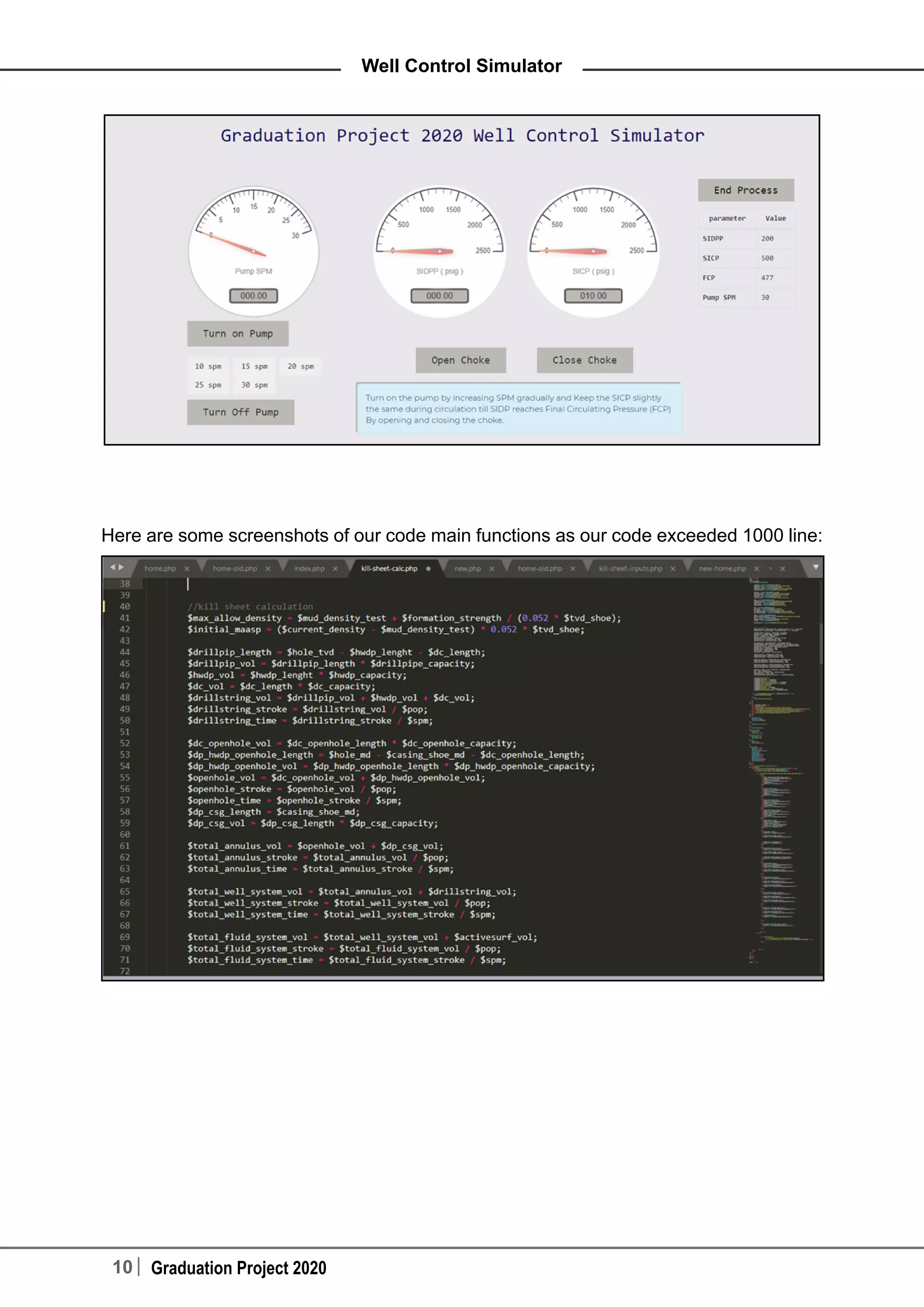
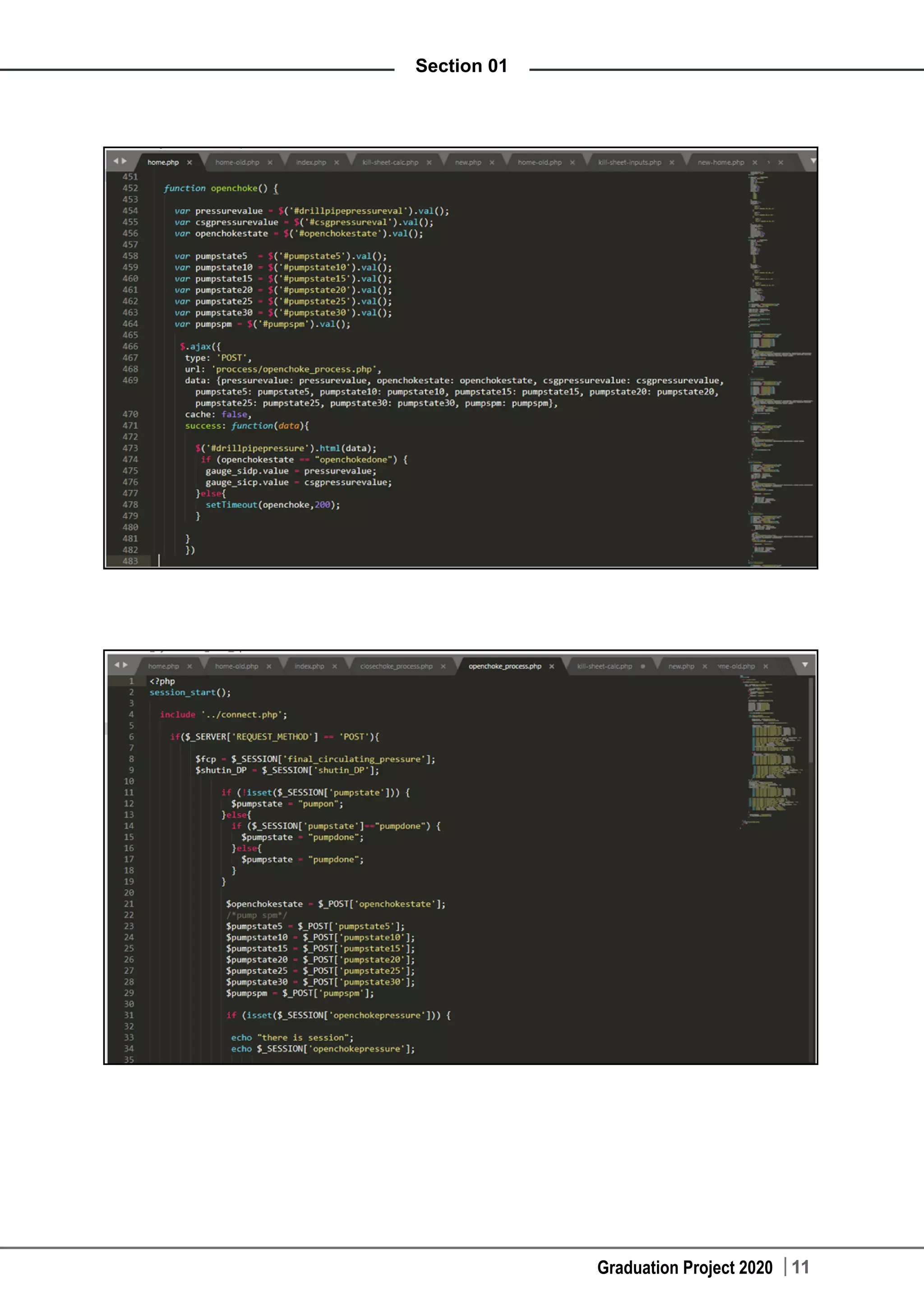
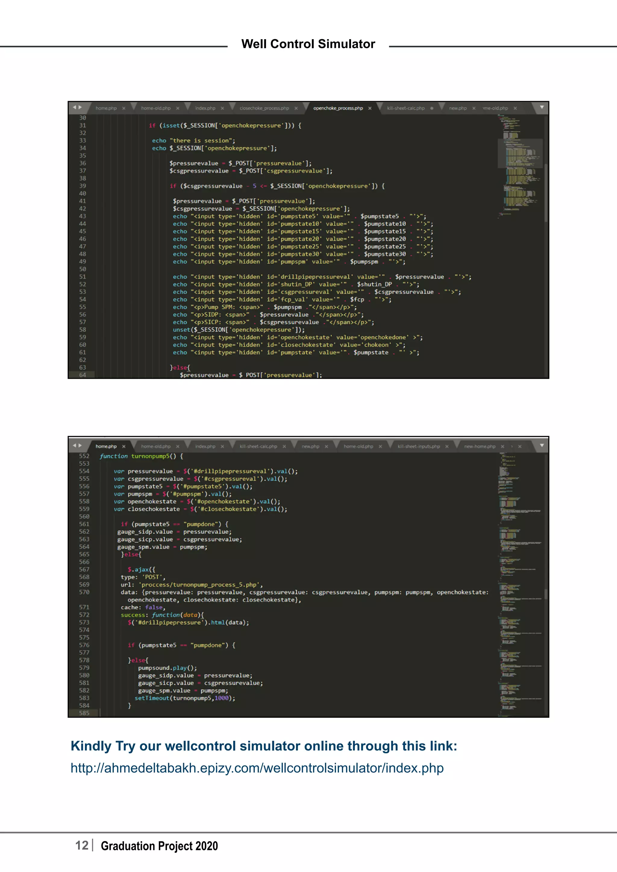
The document discusses kicks in oil and gas wells, factors that affect kick severity, causes of kicks, warning signs of kicks, and kill sheet calculations. It then describes developing a well control simulator as a web application to perform kill sheet calculations and simulate the wait and weight method of well control from start to finish. Screenshots of the simulator interface and code are provided. The simulator allows users to make kill sheet calculations, print the kill sheet, and simulate increasing pump speed while adjusting choke pressure to safely circulate a kick and bring the well under control.
Oil 101 - A Free Introduction to Oil and Gas
Introduction to Oil and Gas Production
Today we’re going to talk about the production function of Upstream. If you missed the previous podcasts on Upstream Fundamentals, Exploration and Drilling, be sure to go check those out. We’ll put the relevant links in the program notes.
The Production and Offshore Construction Module provides a high level overview of production operations. It introduces the offshore contractors and production service providers that assist E&P companies in efficiently producing oil and gas.
We’ll also cover well completions and key measures and drivers that influence production business operations.
We’ll also give some historical perspective on this part of upstream oil and gas operations.
Production
Once oil or gas is found with a wildcat or discovery well, the next step in adding value to reserves is to get the reservoir fluids brought to the surface, or “produce” them. After all, upstream is also called E&P!
Enhanced Oil Recovery
It’s a process for recovering mostly every Barrels of Oil to get out all of remaining oil in it.
And this is done by EOR technologies
Enhanced Oil Recovery
Mainly the following process are done for Enhanced oil recovery
Water injection
Gas injection
Reducing residual oil saturation, SOR (alcohol, polymers, surfactants injection)
Thermal: steam injection (to heating of the reservoir to lower the viscosity)
Brief Introduction into Oil & Gas Industry by Fidan AliyevaFidan Aliyeva
This document presents five stages of the oil field life cycle, their description and some disciplines involved as well as some general facts about the oil and gas.
Drilling fluids are absolutely essential during the drilling process and considered the primary well control.
Know more now about such a very important component of the drilling process.
Oil 101: Introduction to Oil and Gas - UpstreamEKT Interactive
Oil 101: Introduction to Oil and Gas - Upstream
What is Upstream? This Midstream content is derived from our Oil 101 Upstream ebook and can be found in our oil and gas learning community.
This Upstream module includes the following sections (use the links below for quick access):
-Introduction to Upstream
-Upstream Business Characteristics
-Oilfield Services
-Reserves – Formation and Importance
-Production – The First Step in Adding Value
-The Unconventional Future of Upstream
Upstream
What is Upstream? Most oil and gas companies’ business structures are segmented and organized according to business segment, assets, or function.
The upstream segment of the business is also known as the exploration and production (E&P) sector because it encompasses activities related to searching for, recovering and producing crude oil and natural gas.
The upstream segment is all about wells: where to locate them; how deep and how far to drill them; and how to design, construct, operate and manage them to deliver the greatest possible return on investment with the lightest, safest and smallest operational footprint.
Exploration
The exploration sector involves obtaining a lease and permission to drill from the owners of onshore or offshore acreage thought to contain oil or gas, and conducting necessary geological and geophysical (G&G) surveys required to explore for (and hopefully find) economic accumulations of oil or gas.
Drilling
There is always uncertainty in the geological and geophysical survey results. The only way to be sure that a prospect is favorable is to drill an exploratory well. Drilling is physically creating the “borehole” in the ground that will eventually become an oil or gas well. This work is done by rig contractors and service companies in the Oilfield Services business sector.
Production
The production sector of the upstream segment maximizes recovery of petroleum from subsurface reservoirs.
Enhanced Oil Recovery
It’s a process for recovering mostly every Barrels of Oil to get out all of remaining oil in it.
And this is done by EOR technologies
Enhanced Oil Recovery
Mainly the following process are done for Enhanced oil recovery
Water injection
Gas injection
Reducing residual oil saturation, SOR (alcohol, polymers, surfactants injection)
Thermal: steam injection (to heating of the reservoir to lower the viscosity)
Brief Introduction into Oil & Gas Industry by Fidan AliyevaFidan Aliyeva
This document presents five stages of the oil field life cycle, their description and some disciplines involved as well as some general facts about the oil and gas.
Drilling fluids are absolutely essential during the drilling process and considered the primary well control.
Know more now about such a very important component of the drilling process.
Oil 101: Introduction to Oil and Gas - UpstreamEKT Interactive
Oil 101: Introduction to Oil and Gas - Upstream
What is Upstream? This Midstream content is derived from our Oil 101 Upstream ebook and can be found in our oil and gas learning community.
This Upstream module includes the following sections (use the links below for quick access):
-Introduction to Upstream
-Upstream Business Characteristics
-Oilfield Services
-Reserves – Formation and Importance
-Production – The First Step in Adding Value
-The Unconventional Future of Upstream
Upstream
What is Upstream? Most oil and gas companies’ business structures are segmented and organized according to business segment, assets, or function.
The upstream segment of the business is also known as the exploration and production (E&P) sector because it encompasses activities related to searching for, recovering and producing crude oil and natural gas.
The upstream segment is all about wells: where to locate them; how deep and how far to drill them; and how to design, construct, operate and manage them to deliver the greatest possible return on investment with the lightest, safest and smallest operational footprint.
Exploration
The exploration sector involves obtaining a lease and permission to drill from the owners of onshore or offshore acreage thought to contain oil or gas, and conducting necessary geological and geophysical (G&G) surveys required to explore for (and hopefully find) economic accumulations of oil or gas.
Drilling
There is always uncertainty in the geological and geophysical survey results. The only way to be sure that a prospect is favorable is to drill an exploratory well. Drilling is physically creating the “borehole” in the ground that will eventually become an oil or gas well. This work is done by rig contractors and service companies in the Oilfield Services business sector.
Production
The production sector of the upstream segment maximizes recovery of petroleum from subsurface reservoirs.
my presentation about kick tolerance and contain 3 videos
the reference (well drilling & construction) Hussain Rabia
and weatherford essay & videos from youtube
CNG Technical & Hydrogen Blending in Natural Gas pipeline.pptxRishabh Sirvaiya
Technical Presentation of Dispenser, Compressor, Cascade, Cylinder manufacturing & Mass flow meter.
Hydrogen Blending in Natural Gas pipeline of CGD Network
This presentation is about wellbore control. It showcases the causes of well control situations, the types of well control and the calculations that should be made to appropriately control a wild well
In the process of drilling oil wells, we may face the problem of the blowout of oil wells because we do not control the exact time of the well. Therefore, in the above simplified report, it explains how to predict and properly shut-in the well to prevent blowout.
Why Frac & How it works!
Rock Mechanics
Fundamentals of Hydraulic Fracturing
Fracturing models
Design criteria for frac treatments
Frac Equipment
Frac chemicals and proppants
QC for Frac job
Hydraulic fracturing technologies and practices
Episode 44 : Flow Behavior of Granular Materials and PowdersPart IIISAJJAD KHUDHUR ABBAS
Episode 44 : Flow Behavior of Granular Materials and PowdersPart III
Law of hydrodynamics do not apply to the flow of solid granular materials through orifices:
Pressure is not distributed equally in all directions due to the development of arches and to frictional forces between the granules.
The rate of flow is not proportional to the head, except at heads smaller than the container diameter.
No provision is made in hydrodynamics for size and shape of particles, which greatly influence the flow rate.
SAJJAD KHUDHUR ABBAS
Ceo , Founder & Head of SHacademy
Chemical Engineering , Al-Muthanna University, Iraq
Oil & Gas Safety and Health Professional – OSHACADEMY
Trainer of Trainers (TOT) - Canadian Center of Human
Development
Drill stem test (DST) is one of the most famous on-site well testing that is used to unveil critical reservoir and fluid properties such as reservoir pressure, average permeability, skin factor and well potential productivity index. It is relatively cheap on-site test that is done prior to well completion. Upon the DST results, usually, the decision of the well completion is taken.
Welcome to WIPAC Monthly the magazine brought to you by the LinkedIn Group Water Industry Process Automation & Control.
In this month's edition, along with this month's industry news to celebrate the 13 years since the group was created we have articles including
A case study of the used of Advanced Process Control at the Wastewater Treatment works at Lleida in Spain
A look back on an article on smart wastewater networks in order to see how the industry has measured up in the interim around the adoption of Digital Transformation in the Water Industry.
Industrial Training at Shahjalal Fertilizer Company Limited (SFCL)MdTanvirMahtab2
This presentation is about the working procedure of Shahjalal Fertilizer Company Limited (SFCL). A Govt. owned Company of Bangladesh Chemical Industries Corporation under Ministry of Industries.
Overview of the fundamental roles in Hydropower generation and the components involved in wider Electrical Engineering.
This paper presents the design and construction of hydroelectric dams from the hydrologist’s survey of the valley before construction, all aspects and involved disciplines, fluid dynamics, structural engineering, generation and mains frequency regulation to the very transmission of power through the network in the United Kingdom.
Author: Robbie Edward Sayers
Collaborators and co editors: Charlie Sims and Connor Healey.
(C) 2024 Robbie E. Sayers
About
Indigenized remote control interface card suitable for MAFI system CCR equipment. Compatible for IDM8000 CCR. Backplane mounted serial and TCP/Ethernet communication module for CCR remote access. IDM 8000 CCR remote control on serial and TCP protocol.
• Remote control: Parallel or serial interface.
• Compatible with MAFI CCR system.
• Compatible with IDM8000 CCR.
• Compatible with Backplane mount serial communication.
• Compatible with commercial and Defence aviation CCR system.
• Remote control system for accessing CCR and allied system over serial or TCP.
• Indigenized local Support/presence in India.
• Easy in configuration using DIP switches.
Technical Specifications
Indigenized remote control interface card suitable for MAFI system CCR equipment. Compatible for IDM8000 CCR. Backplane mounted serial and TCP/Ethernet communication module for CCR remote access. IDM 8000 CCR remote control on serial and TCP protocol.
Key Features
Indigenized remote control interface card suitable for MAFI system CCR equipment. Compatible for IDM8000 CCR. Backplane mounted serial and TCP/Ethernet communication module for CCR remote access. IDM 8000 CCR remote control on serial and TCP protocol.
• Remote control: Parallel or serial interface
• Compatible with MAFI CCR system
• Copatiable with IDM8000 CCR
• Compatible with Backplane mount serial communication.
• Compatible with commercial and Defence aviation CCR system.
• Remote control system for accessing CCR and allied system over serial or TCP.
• Indigenized local Support/presence in India.
Application
• Remote control: Parallel or serial interface.
• Compatible with MAFI CCR system.
• Compatible with IDM8000 CCR.
• Compatible with Backplane mount serial communication.
• Compatible with commercial and Defence aviation CCR system.
• Remote control system for accessing CCR and allied system over serial or TCP.
• Indigenized local Support/presence in India.
• Easy in configuration using DIP switches.
Hierarchical Digital Twin of a Naval Power SystemKerry Sado
A hierarchical digital twin of a Naval DC power system has been developed and experimentally verified. Similar to other state-of-the-art digital twins, this technology creates a digital replica of the physical system executed in real-time or faster, which can modify hardware controls. However, its advantage stems from distributing computational efforts by utilizing a hierarchical structure composed of lower-level digital twin blocks and a higher-level system digital twin. Each digital twin block is associated with a physical subsystem of the hardware and communicates with a singular system digital twin, which creates a system-level response. By extracting information from each level of the hierarchy, power system controls of the hardware were reconfigured autonomously. This hierarchical digital twin development offers several advantages over other digital twins, particularly in the field of naval power systems. The hierarchical structure allows for greater computational efficiency and scalability while the ability to autonomously reconfigure hardware controls offers increased flexibility and responsiveness. The hierarchical decomposition and models utilized were well aligned with the physical twin, as indicated by the maximum deviations between the developed digital twin hierarchy and the hardware.
Sachpazis:Terzaghi Bearing Capacity Estimation in simple terms with Calculati...Dr.Costas Sachpazis
Terzaghi's soil bearing capacity theory, developed by Karl Terzaghi, is a fundamental principle in geotechnical engineering used to determine the bearing capacity of shallow foundations. This theory provides a method to calculate the ultimate bearing capacity of soil, which is the maximum load per unit area that the soil can support without undergoing shear failure. The Calculation HTML Code included.
CW RADAR, FMCW RADAR, FMCW ALTIMETER, AND THEIR PARAMETERSveerababupersonal22
It consists of cw radar and fmcw radar ,range measurement,if amplifier and fmcw altimeterThe CW radar operates using continuous wave transmission, while the FMCW radar employs frequency-modulated continuous wave technology. Range measurement is a crucial aspect of radar systems, providing information about the distance to a target. The IF amplifier plays a key role in signal processing, amplifying intermediate frequency signals for further analysis. The FMCW altimeter utilizes frequency-modulated continuous wave technology to accurately measure altitude above a reference point.
HEAP SORT ILLUSTRATED WITH HEAPIFY, BUILD HEAP FOR DYNAMIC ARRAYS.
Heap sort is a comparison-based sorting technique based on Binary Heap data structure. It is similar to the selection sort where we first find the minimum element and place the minimum element at the beginning. Repeat the same process for the remaining elements.
NO1 Uk best vashikaran specialist in delhi vashikaran baba near me online vas...Amil Baba Dawood bangali
Contact with Dawood Bhai Just call on +92322-6382012 and we'll help you. We'll solve all your problems within 12 to 24 hours and with 101% guarantee and with astrology systematic. If you want to take any personal or professional advice then also you can call us on +92322-6382012 , ONLINE LOVE PROBLEM & Other all types of Daily Life Problem's.Then CALL or WHATSAPP us on +92322-6382012 and Get all these problems solutions here by Amil Baba DAWOOD BANGALI
#vashikaranspecialist #astrologer #palmistry #amliyaat #taweez #manpasandshadi #horoscope #spiritual #lovelife #lovespell #marriagespell#aamilbabainpakistan #amilbabainkarachi #powerfullblackmagicspell #kalajadumantarspecialist #realamilbaba #AmilbabainPakistan #astrologerincanada #astrologerindubai #lovespellsmaster #kalajaduspecialist #lovespellsthatwork #aamilbabainlahore#blackmagicformarriage #aamilbaba #kalajadu #kalailam #taweez #wazifaexpert #jadumantar #vashikaranspecialist #astrologer #palmistry #amliyaat #taweez #manpasandshadi #horoscope #spiritual #lovelife #lovespell #marriagespell#aamilbabainpakistan #amilbabainkarachi #powerfullblackmagicspell #kalajadumantarspecialist #realamilbaba #AmilbabainPakistan #astrologerincanada #astrologerindubai #lovespellsmaster #kalajaduspecialist #lovespellsthatwork #aamilbabainlahore #blackmagicforlove #blackmagicformarriage #aamilbaba #kalajadu #kalailam #taweez #wazifaexpert #jadumantar #vashikaranspecialist #astrologer #palmistry #amliyaat #taweez #manpasandshadi #horoscope #spiritual #lovelife #lovespell #marriagespell#aamilbabainpakistan #amilbabainkarachi #powerfullblackmagicspell #kalajadumantarspecialist #realamilbaba #AmilbabainPakistan #astrologerincanada #astrologerindubai #lovespellsmaster #kalajaduspecialist #lovespellsthatwork #aamilbabainlahore #Amilbabainuk #amilbabainspain #amilbabaindubai #Amilbabainnorway #amilbabainkrachi #amilbabainlahore #amilbabaingujranwalan #amilbabainislamabad
Using recycled concrete aggregates (RCA) for pavements is crucial to achieving sustainability. Implementing RCA for new pavement can minimize carbon footprint, conserve natural resources, reduce harmful emissions, and lower life cycle costs. Compared to natural aggregate (NA), RCA pavement has fewer comprehensive studies and sustainability assessments.
3. Graduation Project 2020 1
Section 01
Oil and Gas well kicks
Kick is a well control problem in which the pressure found within the drilled rock is higher
than the mud hydrostatic pressure acting on the borehole or rock face. When this occurs,
the greater formation pressure has a tendency to force formation fluids into the wellbore.
This forced fluid flow is called a kick. If the flow is successfully controlled, the kick is
considered to have been killed. An uncontrolled kick that increases in severity may result
in what is known as a “blowout.”
Factors affecting kick severity
Several factors affect the severity of a kick. One factor, for example, is the “permeability” of
rock, which is its ability to allow fluid to move through the rock. Another factor affecting kick
severity is “porosity.” Porosity measures the amount of space in the rock containing fluids.
A rock with high permeability and high porosity has greater potential for a severe kick than
a rock with low permeability and low porosity. For example, sandstone is considered to
have greater kick potential than shale, because sandstone has greater permeability and
greater porosity than shale.
Yet another factor affecting kick severity is the “pressure differential” involved. Pressure
differential is the difference between the formation fluid pressure and the mud hydrostatic
pressure. If the formation pressure is much greater than the hydrostatic pressure, a large
negative differential pressure exists. If this negative differential pressure is coupled with
high permeability and high porosity, a severe kick may occur.
Causes of kicks
Kicks occur as a result of formation pressure being greater than mud hydrostatic pressure,
which causes fluids to flow from the formation into the wellbore. In almost all drilling
operations, the operator attempts to maintain a hydrostatic pressure greater than formation
pressure and, thus, prevent kicks; however, on occasion the formation will exceed the
mud pressure and a kick will occur. Reasons for this imbalance explain the key causes
of kicks:
• Insufficient mud weight.
• Improper hole fill-up during trips.
• Swabbing.
• Cut mud.
• Lost circulation.
4. 2 Graduation Project 2020
Well Control Simulator
Warning signs of kicks
Warning signs and possible kick indicators can be observed at the surface. Each crew
member has the responsibility to recognize and interpret these signs and take proper action.
All signs do not positively identify a kick; some merely warn of potential kick situations.
Key warning signs to watch for include the following:
• Flow rate increase
• Pit volume increase
• Flowing well with pumps off
• Pump pressure decrease and pump stroke increase
• Improper hole fill-up on trips
• String weight change
• Drilling break
• Cut mud weight
Kick indicators
What are the indicators that the well is flowing?
1. Increase in Flow Rate
2. Increase in Pit Level
3. Drop in pump pressure
What Action Should Be Taken?
1. Flow Check(Drilling/Tripping)
2. Shut the well
3. Circulate Bottoms Up
4. Raise Mud Weight
5. Graduation Project 2020 3
Section 01
Kill sheet calculations for vertical wells
Kill sheet calculations it’s very important Sheet when we decided to kill the well.
It used to read the well by determine well parameters/features.
Such as
– Volume, strokes & time Calculations ….why?
– Maximum Mud Weight of Drilling Fluid….why?
– MAASP….why?
– Kill Mud Weight K.M.W. …why?
– Initial/Final Circulating Pressure (ICP,FCP) …. Why?
– Draw Step Down Chart….why?
Sequence of kill sheet solution
1. Draw Your Own well profile case. includes The main features. (Vertical, Deviated,
Horizontal)
2. Location of each Tubular inside Hole.
3. Put the Data on the profile.
4. Start the calculations
Steps for vertical well
First of all we’ve to determine 3 things :-
A- Drill pipe Length = MD - (DC Length + HWDP Length)
B- Open hole Length= MD – Cased hole
C- Drill Collar length
If total length of Drill Collar and HWDP < Open hole section,
So all DC and HWDP in Open hole section.
And then the remaining O.H Section will have DP.
But if total length of Drill Collar and HWDP > Open hole section.
So there will be a part of HWDP or both (HWDP and DC) in
Open hole section.
6. 4 Graduation Project 2020
Well Control Simulator
1- Strokes from Surface to bit:-
Calculate Drill string Volume (DP/HWDP/DC)
For Drill pipe:-
=Drill pipe Capacity bbl./ft. x length of drill pipe
For Heavy walled Drill pipe:-
=HWDP Cap. Bbl./ft. x length of HWDP
For Drill Collar
=DC Cap. Bbl./ft. x length of DC
Then add all of them to obtain Total Volume inside String
No of Strokes =Total Volume (bbl.) / POP (bbl./stroke)
Time=No. of strokes / SPM (min)
2- Strokes from bit to shoe :- assuming the case when open hole > length
of HWDP+DC
Calculate open hole to (DP/HWDP/DC) Volume
For Open Hole / Drill Collar:-
=(O.H /Drill Collar) Capacity bbl./ft. x length of Drill Collar
For Open Hole / Heavy walled Drill pipe:-
=(O.H/ HWDP) Cap. Bbl./ft. x length of HWDP
For Open Hole / Drill Pipe:-
=(O.H/DP) Cap. Bbl./ft. x length of DP
Then add all of them to obtain Total Volume
No of Strokes =Total Volume (bbl.) / POP (bbl./stroke)
Time= No of strokes / SPM. (min)
3- Strokes from bit to surface:-
Calculate cased hole to DP Volume:-
=Drill pipe Capacity bbl./ft. x length cased hole ft.
No of Strokes =Total Volume (bbl.) / POP (bbl./stroke)
So Strokes from Bit to surface = strokes from bit to shoe +strokes from shoe to surface
Time = No. of strokes/ SPM (min)
7. Graduation Project 2020 5
Section 01
4- Time for Complete Circulation=time from surface to bit + time from bit to
surface + surface line time
5- Kill Mud Weight:-
Kill Mud Weight = SIDPP/(0.052xTVD) + Current M.wt.
6- Initial Circulating Pressure:-
ICP = DYNAMIC PRESSURE LOSS + SIDPP
7- Final Circulating Pressure:-
FCP= DYNAMIC PRESSURE LOSS x (K.M.W)/(Current M.Wt )
8- MAASP with current mud weight:-
Maximum Allowable M.WT (ppg) =( (LOT Pressure)/(0.052xShoe TVD )+Lot M.wt)
MAASP (psi) = (Maximum M.wt. - Current M.wt.)x0.052xShoe TVD
9- MAASP after circulation of kill mud:-
= Maximum M.wt. – K.M.W x 0.052 x Shoe TVD
10- Step Down Chart
Pressure Drop=(ICP-FCP)x100 / String Strokes
Example for step Down chart
8. 6 Graduation Project 2020
Well Control Simulator
Wait and Weight Method
The “Wait and Weight” is sometimes referred to as the ‘Engineers Method’ or the ‘One
Circulation Method’. It does, at least in theory, kill the well in one circulation.
Once the well is shut in and pressures stabilised, the shut in drill pipe pressure is used
to calculate the kill mud weight. Mud of the required weight is made up in the mud pits.
When ready, kill mud is pumped down the drill pipe. At commencement, enough drill
pipe pressure must be held to circulate the mud, plus a reserve equivalent to the original
shut in drill pipe pressure. This total steadily decreases as the mud goes down to the bit,
until with kill mud at the bit, the required pressure is simply that needed to pump kill mud
around the well.
The choke is adjusted to reduce drill pipe pressure while kill mud is pumped down the
string. With kill mud at the bit, the static head of mud in the drill pipe balances formation
pressure. For the remainder of the circulation, as the influx is pumped to the surface,
followed by drill pipe contents and the kill mud, the drill pipe pressure is held at the final
circulating pressure by choke adjustment.
Advantages of the Wait and Weight Method
• Lowest wellbore pressures, and lowest surface pressures - this means less
equipment stress.
• Minimum ‘on-choke’ circulating time - less chance of washing out the choke.
Disadvantages of the Wait and Weight Method
• Considerable waiting time (while weighting up) - gas migration.
• If large increases in mud weight required, this is difficult to do uniformly in one stage.
Steps of the weight and weight method for well control are as follow:
• Shut in the well.
• Allow pressure to stabilize and record stabilized shut in casing pressure, initial shut
in drill pipe pressure, and pit gain. If you have a float in the drill string, you must bump
the float in order to see the shut-in drill pipe pressure
• Perform well control calculations
• Raise mud weight in the system to required kill mud weight
• Establish circulation to required kill rate by holding casing pressure constant
• Follow drill pipe schedule until kill weight mud to the bit.
• Hold drill pipe pressure constant once kill weight mud out of the bit until complete
circulation.
• Check mud weight out and ensure that mud weight out is equal to kill mud weight.
• Shut down and flow check to confirm if a well is static
• Circulate and condition mud if required
9. Graduation Project 2020 7
Section 01
Well Control Simulator as a web application
We developed a simulator for kill sheet calculations and wait & weight method as a website
application using different web programming languages including mainly JavaScript, PHP,
and HTML.
Our simulator can:
• Make Kill sheet calculations
• Print the kill sheet
• Simulate wait & weight method from A to Z
Wait & weight simulation process description:
• You turn on the pump by increasing pump spm gradually 5 spm by 5 spm
• While you are increasing pump spm, you must keep SICP slightly above its recorded
value in the kill sheet
• This can be done by opening and closing choke buttons
• By this way you can circulate the kick safely and put well under control
Here are some screenshots of our simulator:
14. 12 Graduation Project 2020
Well Control Simulator
Kindly Try our wellcontrol simulator online through this link:
http://ahmedeltabakh.epizy.com/wellcontrolsimulator/index.php
16. 14 Graduation Project 2020
IPR Plotter
IPR Plotter (iOS App)
Description:
• Our App requires some inputs to draw IPR for two types of reservoir:
1. Oil Reservoir
2. Gas Reservoir
• Our App is calculated and draw IPR curve based on four methods (two method for
each reservoir type)
• We used Vogel Method and Standing Method for oil reservoir
• We used Backpressure method and Forchiemer method for gas reservoir
Our App include predication for Future IPR in Gas Reservoir
Screenshots of App:
Screenshots of Code:
1. Backpressure Method
2. Forchiemer method