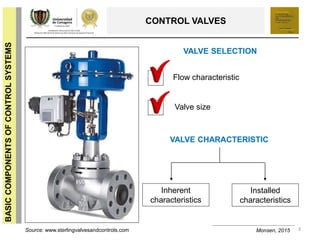
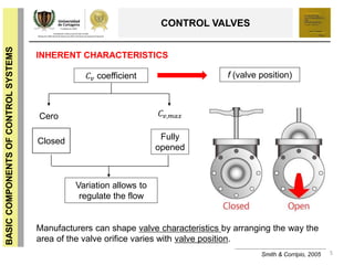
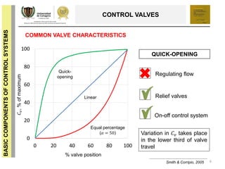
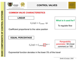
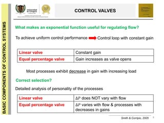
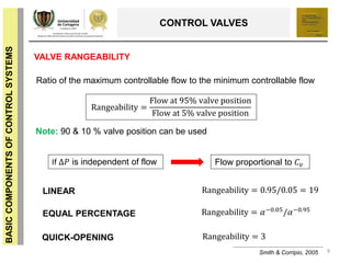
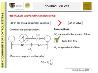
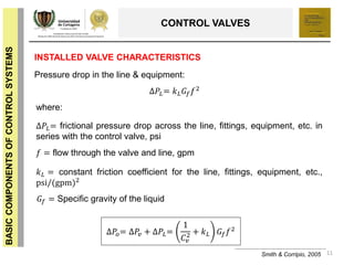
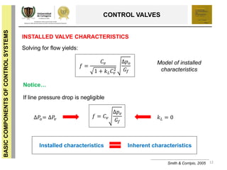
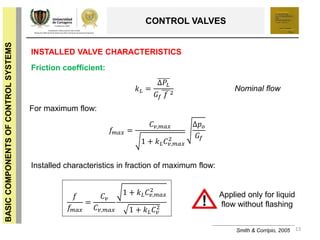
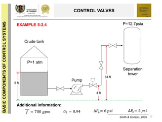
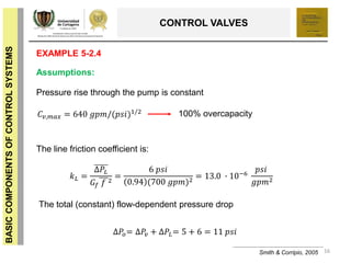
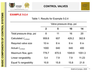
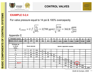
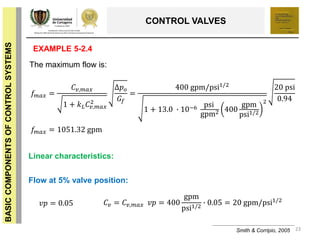
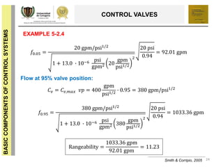
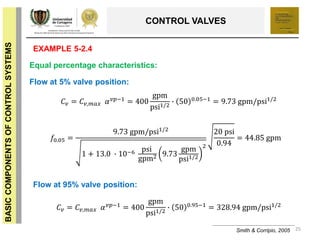
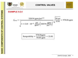
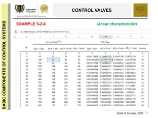
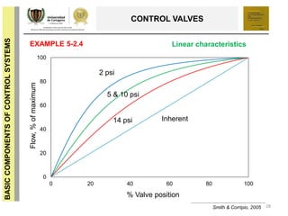
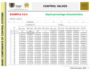
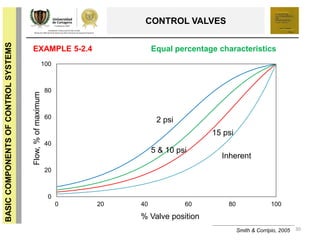
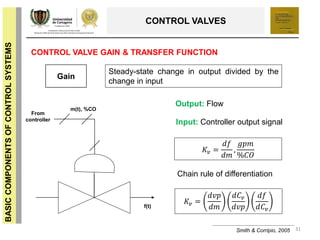
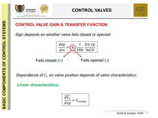
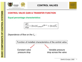
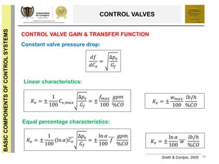
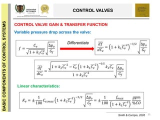
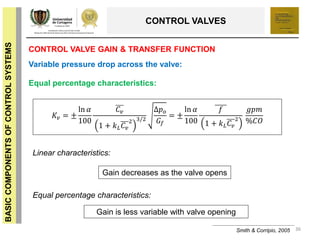
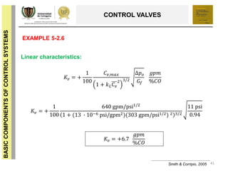
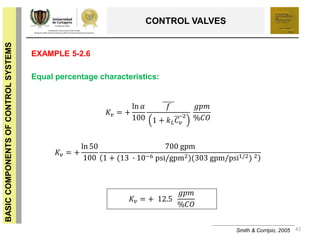
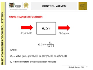
CONTROL VALVES: CHARACTERISTICS, GAIN
& TRANSFER FUNCTION
1
CONTROL PROCESS
BASICCOMPONENTSOFCONTROLSYSTEMS
"Good, better, best. Never let it rest. 'Til your good is better and your better is best." - St. Jerome
CONTROL VALVES: CHARACTERISTICS, GAIN &
TRANSFER FUNCTION
IRIS BUSTAMANTE PÁJARO*
ANGIE CASTILLO GUEVARA*
ALVARO JOSE GARCÍA PADILLA *
KARIANA ANDREA MORENO SADDER*
LUIS ALBERTO PATERNINA NUÑEZ*
9th SEMESTER
CHEMICAL ENGINEERING PROGRAM
UNIVERSITY OF CARTAGENA
2
CONTROL PROCESS
BASICCOMPONENTSOFCONTROLSYSTEMS
3
BASICCOMPONENTSOFCONTROLSYSTEMS
CONTROL VALVES
VALVE SELECTION
Monsen, 2015
Flow characteristic
Valve size
VALVE CHARACTERISTIC
Inherent
characteristics
Installed
characteristics
Source: www.sterlingvalvesandcontrols.com
4
BASICCOMPONENTSOFCONTROLSYSTEMS
CONTROL VALVES
Monsen, 2015
INHERENT CHARACTERISTICS
Valve flow capacity Valve opening NO system effects involved
Who provides it?
Manufacturer
Based on tests performed in a system where great care is taken to
ensure that the pressure drop across the test valve is held constant at
all valve openings and flow rates
5
BASICCOMPONENTSOFCONTROLSYSTEMS
CONTROL VALVES
Smith & Corripio, 2005
INHERENT CHARACTERISTICS
𝐶𝑣 coefficient f (valve position)
Cero 𝐶 𝑣,𝑚𝑎𝑥
Fully
opened
Closed
Variation allows to
regulate the flow
Manufacturers can shape valve characteristics by arranging the way the
area of the valve orifice varies with valve position.
6
BASICCOMPONENTSOFCONTROLSYSTEMS
CONTROL VALVES
Smith & Corripio, 2005
COMMON VALVE CHARACTERISTICS
0
20
40
60
80
100
0 20 40 60 80 100
% valve position
𝐶𝑣,%ofmaximum
Equal percentage
(𝛼 = 50)
Linear
Quick-
opening
QUICK-OPENING
Regulating flow
Relief valves
On-off control system
Variation in 𝐶 𝑣 takes place
in the lower third of valve
travel
7
BASICCOMPONENTSOFCONTROLSYSTEMS
CONTROL VALVES
Smith & Corripio, 2005
COMMON VALVE CHARACTERISTICS
LINEAR
𝐶 𝑣 𝑣𝑝 = 𝐶 𝑣,𝑚𝑎𝑥 𝑣𝑝
EQUAL PERCENTAGE
𝐶 𝑣 𝑣𝑝 = 𝐶 𝑣,𝑚𝑎𝑥 𝛼 𝑣𝑝−1
To regulate flow
What is it used for?
Coefficient proportional to the valve position
Exponential function deviates in the lower 5% of the travel
Rangeability
parameter: 50 (most
common) or 100
8
BASICCOMPONENTSOFCONTROLSYSTEMS
CONTROL VALVES
Smith & Corripio, 2005
What makes an exponential function useful for regulating flow?
To achieve uniform control performance Control loop with constant gain
Linear valve Constant gain
Equal percentage valve Gain increases as valve opens
Most processes exhibit decrease in gain with increasing load
Correct selection?
Detailed analysis of personality of the processes
Linear valve ∆𝑃 does NOT vary with flow
Equal percentage valve ∆𝑃 varies with flow & processes with
decreases in gains
9
BASICCOMPONENTSOFCONTROLSYSTEMS
CONTROL VALVES
Smith & Corripio, 2005
VALVE RANGEABILITY
Ratio of the maximum controllable flow to the minimum controllable flow
Rangeability =
Flow at 95% valve position
Flow at 5% valve position
Note: 90 & 10 % valve position can be used
If ∆𝑃 is independent of flow Flow proportional to 𝐶𝑣
LINEAR
EQUAL PERCENTAGE
QUICK-OPENING
Rangeability = 0.95/0.05 = 19
Rangeability = 𝛼−0.05
/𝛼−0.95
Rangeability = 3
10
BASICCOMPONENTSOFCONTROLSYSTEMS
CONTROL VALVES
Smith & Corripio, 2005
INSTALLED VALVE CHARACTERISTICS
∆𝑃 in the line & equipment in series ∆𝑃 in valve
Consider the piping system:
𝑓
∆𝑃𝐿 ∆𝑃𝑣
∆𝑃𝑜
Assumptions:
∆𝑃𝐿 varies with the square of flow
∆𝑃𝑜 independient of flow
Turbulent flow
Pressure drop across the valve:
∆𝑃𝑣= 𝐺𝑓
𝑓2
𝐶𝑣
2
11
BASICCOMPONENTSOFCONTROLSYSTEMS
CONTROL VALVES
Smith & Corripio, 2005
INSTALLED VALVE CHARACTERISTICS
Pressure drop in the line & equipment:
∆𝑃𝐿= 𝑘 𝐿 𝐺𝑓 𝑓2
where:
∆𝑃𝐿= frictional pressure drop across the line, fittings, equipment, etc. in
series with the control valve, psi
𝑓 = flow through the valve and line, gpm
𝑘 𝐿 = constant friction coefficient for the line, fittings, equipment, etc.,
psi/(gpm)2
𝐺𝑓 = Specific gravity of the liquid
∆𝑃𝑜= ∆𝑃𝑣 + ∆𝑃𝐿=
1
𝐶 𝑣
2 + 𝑘 𝐿 𝐺𝑓 𝑓2
12
BASICCOMPONENTSOFCONTROLSYSTEMS
CONTROL VALVES
Smith & Corripio, 2005
INSTALLED VALVE CHARACTERISTICS
Solving for flow yields:
𝑓 =
𝐶 𝑣
1 + 𝑘 𝐿 𝐶 𝑣
2
∆𝑝 𝑜
𝐺𝑓
Model of installed
characteristics
Notice…
If line pressure drop is negligible
𝑘 𝐿 = 0∆𝑃𝑜= ∆𝑃𝑣
𝑓 = 𝐶 𝑣
∆𝑝 𝑣
𝐺𝑓
Installed characteristics Inherent characteristics
13
BASICCOMPONENTSOFCONTROLSYSTEMS
CONTROL VALVES
Smith & Corripio, 2005
INSTALLED VALVE CHARACTERISTICS
Friction coefficient:
𝑘 𝐿 =
∆𝑃𝐿
𝐺𝑓 𝑓 2
Nominal flow
For maximum flow:
𝑓𝑚𝑎𝑥 =
𝐶 𝑣,𝑚𝑎𝑥
1 + 𝑘 𝐿 𝐶𝑣,𝑚𝑎𝑥
2
∆𝑝 𝑜
𝐺𝑓
Installed characteristics in fraction of maximum flow:
𝑓
𝑓𝑚𝑎𝑥
=
𝐶 𝑣
𝐶𝑣,𝑚𝑎𝑥
1 + 𝑘 𝐿 𝐶 𝑣,𝑚𝑎𝑥
2
1 + 𝑘 𝐿 𝐶𝑣
2
Applied only for liquid
flow without flashing
14
BASICCOMPONENTSOFCONTROLSYSTEMS
CONTROL VALVES
Smith & Corripio, 2005
EXAMPLE 5-2.4
For the valve of Example 5-2.3, find the maximum flow through the
valve, the installed flow characteristics and the rangeability of the
valve. Assume both linear and equal percentage characteristics with
a rangeability parameter of 50. Analyze the effect of varying the
pressure drop across the valve at nominal flow.
Solution:
Before resolving the exercise, we must identify all the information
supplied by it. The Example 5-2.3 consists in a process for
transferring an oil from a storage tank to a separation tower.
15
BASICCOMPONENTSOFCONTROLSYSTEMS
CONTROL VALVES
Smith & Corripio, 2005
EXAMPLE 5-2.4 P=12.7psia
P=1 atm
Crude tank
Pump
Separation
tower
8 ft
4 ft
64 ft
Additional information:
𝑓 = 700 𝑔𝑝𝑚 𝐺𝑓 = 0.94 ∆𝑃𝐿= 6 𝑝𝑠𝑖 ∆𝑃𝑣= 5 𝑝𝑠𝑖
16
BASICCOMPONENTSOFCONTROLSYSTEMS
CONTROL VALVES
Assumptions:
Smith & Corripio, 2005
Pressure rise through the pump is constant
The total (constant) flow-dependent pressure drop
The line friction coefficient is:
EXAMPLE 5-2.4
𝐶 𝑣,𝑚𝑎𝑥 = 640 𝑔𝑝𝑚/(𝑝𝑠𝑖)1/2 100% overcapacity
𝑘 𝐿 =
∆𝑃𝐿
𝐺𝑓 𝑓 2
=
6 𝑝𝑠𝑖
0.94 (700 𝑔𝑝𝑚)2 = 13.0 ∙ 10−6
𝑝𝑠𝑖
𝑔𝑝𝑚2
∆𝑃𝑜= ∆𝑃𝑣 + ∆𝑃𝐿= 5 + 6 = 11 𝑝𝑠𝑖
17
BASICCOMPONENTSOFCONTROLSYSTEMS
CONTROL VALVES
Smith & Corripio, 2005
EXAMPLE 5-2.4
The maximum flow is:
𝑓𝑚𝑎𝑥 =
𝐶 𝑣,𝑚𝑎𝑥
1 + 𝑘 𝐿 𝐶𝑣,𝑚𝑎𝑥
2
∆𝑝 𝑜
𝐺𝑓
=
640 gpm/psi1/2
1 + 13.0 ∙ 10−6 psi
gpm2 640
gpm
psi1/2
2
11 psi
0.94
𝑓𝑚𝑎𝑥 = 870 gpm Note: Maximum flow is much less than twice
the nominal flow, 1400 gpm (100%
overcapacity)
Linear characteristics:
𝑣𝑝 = 0.05 𝐶𝑣 = 𝐶𝑣,𝑚𝑎𝑥 𝑣𝑝 = 640
gpm
psi1/2
∙ 0.05 = 32 gpm/psi1/2
Flow at 5% valve position:
18
BASICCOMPONENTSOFCONTROLSYSTEMS
CONTROL VALVES
Smith & Corripio, 2005
EXAMPLE 5-2.4
𝐶 𝑣 = 𝐶 𝑣,𝑚𝑎𝑥 𝑣𝑝 = 640
gpm
psi1/2
∙ 0.95 = 608 gpm/psi1/2
𝑓0.95 =
608 gpm/psi1/2
1 + 13.0 ∙ 10−6 psi
gpm2 608
gpm
psi1/2
2
11 psi
0.94
= 863.2 gpm
Rangeability =
863.2 gpm
108.8 gpm
= 7.93
Flow at 95% valve position:
𝑓0.05 =
32 gpm/psi1/2
1 + 13.0 ∙ 10−6 psi
gpm2 32
gpm
psi1/2
2
11 psi
0.94
= 108.8 gpm
19
BASICCOMPONENTSOFCONTROLSYSTEMS
CONTROL VALVES
Smith & Corripio, 2005
EXAMPLE 5-2.4
𝐶 𝑣 = 𝐶 𝑣,𝑚𝑎𝑥 𝛼 𝑣𝑝−1 = 640
gpm
psi1/2
∙ 50 0.05−1 = 15.6 gpm/psi1/2
𝑓0.05 =
15.6gpm/psi1/2
1 + 13.0 ∙ 10−6 psi
gpm2 15.6
gpm
psi1/2
2
11 psi
0.94
= 53.2 gpm
Flow at 95% valve position:
Equal percentage characteristics:
𝐶 𝑣 = 𝐶 𝑣,𝑚𝑎𝑥 𝛼 𝑣𝑝−1 = 640
gpm
psi1/2
∙ 50 0.95−1 = 526 gpm/psi1/2
Flow at 5% valve position:
20
BASICCOMPONENTSOFCONTROLSYSTEMS
CONTROL VALVES
Smith & Corripio, 2005
EXAMPLE 5-2.4
𝑓0.95 =
526 gpm/psi1/2
1 + 13.0 ∙ 10−6 psi
gpm2 526
gpm
psi1/2
2
11 psi
0.94
= 839 gpm
Rangeability =
839 gpm
53.2 gpm
= 15.8
Repeat the previous steps but changing valve pressure drop, psi. The aim
of this is to obtain a curve of %valve position versus flow, % of maximum
at different valve pressure drop.
21
BASICCOMPONENTSOFCONTROLSYSTEMS
CONTROL VALVES
Smith & Corripio, 2005
EXAMPLE 5-2.4
Valve pressure drop, psi
2 5 10 14
Total pressure drop, psi 8 11 16 20
Calculated 𝐶 𝑣,𝑚𝑎𝑥 959.8 607 429.2 362.8
Required valve size 10 in 8 in 8 in 6 in
Actual 𝐶 𝑣,𝑚𝑎𝑥 1000 640 640 400
Maximum flow, gpm 779.7 870.5 1049.9 1051.3
Linear rangeability 5.4 7.9 7.9 11.23
Equal % rangeability 10.8 15.8 15.8 21.8
Table 1. Results for Example 5-2.4
22
BASICCOMPONENTSOFCONTROLSYSTEMS
CONTROL VALVES
Smith & Corripio, 2005
EXAMPLE 5-2.4
For valve pressure equal to 14 psi & 100% overcapacity
𝐶 𝑣,𝑚𝑎𝑥 = 2 𝑓
𝐺𝑓
∆𝑃𝑣
= 2 700 𝑔𝑝𝑚
0.94
14
= 362.8
𝑔𝑝𝑚
𝑝𝑠𝑖
Appendix C
23
BASICCOMPONENTSOFCONTROLSYSTEMS
CONTROL VALVES
Smith & Corripio, 2005
EXAMPLE 5-2.4
The maximum flow is:
𝑓𝑚𝑎𝑥 =
𝐶 𝑣,𝑚𝑎𝑥
1 + 𝑘 𝐿 𝐶𝑣,𝑚𝑎𝑥
2
∆𝑝 𝑜
𝐺𝑓
=
400 gpm/psi1/2
1 + 13.0 ∙ 10−6 psi
gpm2 400
gpm
psi1/2
2
20 psi
0.94
𝑓𝑚𝑎𝑥 = 1051.32 gpm
Linear characteristics:
𝑣𝑝 = 0.05 𝐶 𝑣 = 𝐶 𝑣,𝑚𝑎𝑥 𝑣𝑝 = 400
gpm
psi1/2
∙ 0.05 = 20 gpm/psi1/2
Flow at 5% valve position:
24
BASICCOMPONENTSOFCONTROLSYSTEMS
CONTROL VALVES
Smith & Corripio, 2005
EXAMPLE 5-2.4
𝑓0.05 =
20 gpm/psi1/2
1 + 13.0 ∙ 10−6 psi
gpm2 20
gpm
psi1/2
2
20 psi
0.94
= 92.01 gpm
𝐶 𝑣 = 𝐶 𝑣,𝑚𝑎𝑥 𝑣𝑝 = 400
gpm
psi1/2
∙ 0.95 = 380 gpm/psi1/2
𝑓0.95 =
380 gpm/psi1/2
1 + 13.0 ∙ 10−6 psi
gpm2 380
gpm
psi1/2
2
20 psi
0.94
= 1033.36 gpm
Rangeability =
1033.36 gpm
92.01 gpm
= 11.23
Flow at 95% valve position:
25
BASICCOMPONENTSOFCONTROLSYSTEMS
CONTROL VALVES
Smith & Corripio, 2005
EXAMPLE 5-2.4
𝐶 𝑣 = 𝐶 𝑣,𝑚𝑎𝑥 𝛼 𝑣𝑝−1 = 400
gpm
psi1/2
∙ 50 0.05−1 = 9.73 gpm/psi1/2
𝑓0.05 =
9.73 gpm/psi1/2
1 + 13.0 ∙ 10−6 psi
gpm2 9.73
gpm
psi1/2
2
20 psi
0.94
= 44.85 gpm
Flow at 95% valve position:
Equal percentage characteristics:
𝐶 𝑣 = 𝐶 𝑣,𝑚𝑎𝑥 𝛼 𝑣𝑝−1 = 400
gpm
psi1/2
∙ 50 0.95−1 = 328.94 gpm/psi1/2
Flow at 5% valve position:
26
BASICCOMPONENTSOFCONTROLSYSTEMS
CONTROL VALVES
Smith & Corripio, 2005
EXAMPLE 5-2.4
𝑓0.95 =
328.94 gpm/psi1/2
1 + 13.0 ∙ 10−6 psi
gpm2 328.94
gpm
psi1/2
2
20 psi
0.94
= 978.06 gpm
Rangeability =
978.06gpm
44.85 gpm
= 21.81
27
BASICCOMPONENTSOFCONTROLSYSTEMS
CONTROL VALVES
Smith & Corripio, 2005
EXAMPLE 5-2.4 Linear characteristics
28
BASICCOMPONENTSOFCONTROLSYSTEMS
CONTROL VALVES
Smith & Corripio, 2005
EXAMPLE 5-2.4
0
20
40
60
80
100
0 20 40 60 80 100
% Valve position
Flow,%ofmaximum
Inherent
2 psi
5 & 10 psi
Linear characteristics
14 psi
29
BASICCOMPONENTSOFCONTROLSYSTEMS
CONTROL VALVES
Smith & Corripio, 2005
EXAMPLE 5-2.4 Equal percentage characteristics
30
BASICCOMPONENTSOFCONTROLSYSTEMS
CONTROL VALVES
Smith & Corripio, 2005
EXAMPLE 5-2.4
0
20
40
60
80
100
0 20 40 60 80 100
% Valve position
Flow,%ofmaximum
Inherent
2 psi
5 & 10 psi
Equal percentage characteristics
15 psi
31
BASICCOMPONENTSOFCONTROLSYSTEMS
CONTROL VALVES
Smith & Corripio, 2005
CONTROL VALVE GAIN & TRANSFER FUNCTION
Steady-state change in output divided by the
change in input
Gain
From
controller
m(t), %CO
f(t)
Output: Flow
Input: Controller output signal
𝐾𝑣 =
𝑑𝑓
𝑑𝑚
,
𝑔𝑝𝑚
%𝐶𝑂
𝐾𝑣 =
𝑑𝑣𝑝
𝑑𝑚
𝑑𝐶 𝑣
𝑑𝑣𝑝
𝑑𝑓
𝑑𝐶 𝑣
Chain rule of differentiation
32
BASICCOMPONENTSOFCONTROLSYSTEMS
CONTROL VALVES
CONTROL VALVE GAIN & TRANSFER FUNCTION
Sign depends on whether valve fails closed or opened:
𝑑𝑣𝑝
𝑑𝑚
= ±
1
100
frn 𝑣𝑝
%𝐶𝑂
Fails closed (+) Fails opened (-)
Dependence of 𝐶 𝑣 on valve position depends of valve characteristics:
Linear characteristics:
𝑑𝐶 𝑣
𝑑𝑣𝑝
= 𝐶 𝑣,𝑚𝑎𝑥
Smith & Corripio, 2005
33
BASICCOMPONENTSOFCONTROLSYSTEMS
CONTROL VALVES
CONTROL VALVE GAIN & TRANSFER FUNCTION
Equal percentage characteristics:
𝑑𝐶 𝑣
𝑑𝑣𝑝
= (ln 𝛼)𝐶 𝑣,𝑚𝑎𝑥 𝛼 𝑣𝑝−1
= (ln 𝛼)𝐶 𝑣
Smith & Corripio, 2005
Dependence of flow on the 𝐶 𝑣 :
Function of installed characteristics of the control valve
Constant valve
pressure drop
Variable pressure
drop across the valve
34
BASICCOMPONENTSOFCONTROLSYSTEMS
CONTROL VALVES
CONTROL VALVE GAIN & TRANSFER FUNCTION
Constant valve pressure drop:
Smith & Corripio, 2005
𝑑𝑓
𝑑𝐶𝑣
=
∆𝑝 𝑣
𝐺𝑓
Linear characteristics:
𝐾𝑣 = ±
1
100
𝐶 𝑣,𝑚𝑎𝑥
∆𝑝 𝑣
𝐺𝑓
= ±
𝑓𝑚𝑎𝑥
100
𝑔𝑝𝑚
%𝐶𝑂
𝐾𝑣 = ±
𝑤 𝑚𝑎𝑥
100
𝑙𝑏/ℎ
%𝐶𝑂
Equal percentage characteristics:
𝐾𝑣 = ±
1
100
(ln 𝛼)𝐶 𝑣
∆𝑝 𝑣
𝐺𝑓
= ±
ln 𝛼
100
𝑓
𝑔𝑝𝑚
%𝐶𝑂 𝐾𝑣 = ±
ln 𝛼
100
𝑤
𝑙𝑏/ℎ
%𝐶𝑂
35
BASICCOMPONENTSOFCONTROLSYSTEMS
CONTROL VALVES
CONTROL VALVE GAIN & TRANSFER FUNCTION
Variable pressure drop across the valve:
Smith & Corripio, 2005
𝑑𝑓
𝑑𝐶𝑣
= 1 + 𝑘 𝐿 𝐶 𝑣
2 −3/2 ∆𝑝 𝑜
𝐺𝑓
𝑑𝑓
𝑑𝐶 𝑣
=
1 + 𝑘 𝐿 𝐶 𝑣
2
− 𝐶 𝑣 1 + 𝑘 𝐿 𝐶 𝑣
2 −0.5
𝑘 𝐿 𝐶 𝑣
1 + 𝑘 𝐿 𝐶 𝑣
2
∆𝑝 𝑜
𝐺𝑓
Differentiate
𝑓 =
𝐶 𝑣
1 + 𝑘 𝐿 𝐶 𝑣
2
∆𝑝 𝑜
𝐺𝑓
Linear characteristics:
𝐾𝑣 = ±
1
100
𝐶 𝑣,𝑚𝑎𝑥 1 + 𝑘 𝐿 𝐶 𝑣
2 −3/2 ∆𝑝 𝑜
𝐺𝑓
= ±
1
100
𝑓𝑚𝑎𝑥
1 + 𝑘 𝐿 𝐶 𝑣
2
𝑔𝑝𝑚
%𝐶𝑂
36
BASICCOMPONENTSOFCONTROLSYSTEMS
CONTROL VALVES
CONTROL VALVE GAIN & TRANSFER FUNCTION
Variable pressure drop across the valve:
Smith & Corripio, 2005
𝐾𝑣 = ±
ln 𝛼
100
𝐶 𝑣
1 + 𝑘 𝐿 𝐶 𝑣
2 3/2
∆𝑝 𝑜
𝐺𝑓
= ±
ln 𝛼
100
𝑓
1 + 𝑘 𝐿 𝐶 𝑣
2
𝑔𝑝𝑚
%𝐶𝑂
Equal percentage characteristics:
Linear characteristics:
Equal percentage characteristics:
Gain decreases as the valve opens
Gain is less variable with valve opening
37
BASICCOMPONENTSOFCONTROLSYSTEMS
CONTROL VALVES
Smith & Corripio, 2005
EXAMPLE 5-2.5
Find the gain and the valve position at design conditions for the
steam valve of Example 5-2.2. Assume that the 10 –in. valve with
𝐶 𝑣,𝑚𝑎𝑥 = 1000 is selected and that the pressure around the valve are
independent of flow. Consider both a valve with linear characteristics
and an equal percentage valve with rangeability parameter of 50. For
the latter, find the gain at the nominal flow of 16100 lb/h.
Constant pressure drop
Valve fails closed to prevent overheating the reboiler, then the valve
gain is positive.
Assumptions:
38
BASICCOMPONENTSOFCONTROLSYSTEMS
CONTROL VALVES
Smith & Corripio, 2005
EXAMPLE 5-2.5
Valve position at designed flow
𝑣𝑝 =
𝐶 𝑣
𝐶 𝑣,𝑚𝑎𝑥
=
440 gpm/psi1/2
1000 gpm/psi1/2
= 0.44
Calculated in Example 5-2.2.
The gain is
𝐾𝑣 = +
𝑤 𝑚𝑎𝑥
100
=
1
100
16100 𝑙𝑏/ℎ
1000 gpm/psi1/2
440 gpm/psi1/2
Linear characteristics:
𝐾𝑣 = 366
𝑙𝑏/ℎ
%𝐶𝑂
Note: To estimate maximum
flow we used 𝐶𝑣 ratios
39
BASICCOMPONENTSOFCONTROLSYSTEMS
CONTROL VALVES
Smith & Corripio, 2005
EXAMPLE 5-2.5
Valve position at designed flow
𝛼 𝑣𝑝−1
=
𝐶 𝑣
𝐶 𝑣,𝑚𝑎𝑥
=
440 gpm/psi1/2
1000 gpm/psi1/2
= 0.44
The gain is
𝐾𝑣 = +
ln 𝛼
100
𝑤 =
ln 50
100
16100 𝑙𝑏/ℎ
𝐾𝑣 = 630
𝑙𝑏/ℎ
%𝐶𝑂
Equal percentage characteristics:
𝑣𝑝 =
ln 0.44
ln 50
+ 1 = 0.79
40
BASICCOMPONENTSOFCONTROLSYSTEMS
CONTROL VALVES
Smith & Corripio, 2005
EXAMPLE 5-2.6
∆𝑃𝑜 = 11 psi, 𝑓 = 700 gpm, 𝑘 𝐿 = 13 ∙ 10−6
𝑝𝑠𝑖/𝑔𝑝𝑚2
, 𝐶𝑣 =
303 𝑔𝑝𝑚/𝑝𝑠𝑖1/2
, and ,𝐶 𝑣,𝑚𝑎𝑥 = 640 𝑔𝑝𝑚/𝑝𝑠𝑖1/2
.
Variable pressure drop
Calculate the gain of the valve in Example 5-2.4. at nominal flow.
Consider both linear valve and an equal percentage valve with
rangeability parameter of 50.
Assumptions:
Valve fails closed, so its gain is positive because the controller signal
opens it.
Information:
41
BASICCOMPONENTSOFCONTROLSYSTEMS
CONTROL VALVES
Smith & Corripio, 2005
EXAMPLE 5-2.6
Linear characteristics:
𝐾𝑣 = +
1
100
𝐶 𝑣,𝑚𝑎𝑥
1 + 𝑘 𝐿 𝐶 𝑣
2 3/2
∆𝑝 𝑜
𝐺𝑓
𝑔𝑝𝑚
%𝐶𝑂
𝐾𝑣 = +
1
100
640 gpm/psi1/2
1 + (13 ∙ 10−6 psi/gpm2)(303 gpm/psi1/2) 2 3/2
11 psi
0.94
𝐾𝑣 = +6.7
𝑔𝑝𝑚
%𝐶𝑂
42
BASICCOMPONENTSOFCONTROLSYSTEMS
CONTROL VALVES
Smith & Corripio, 2005
EXAMPLE 5-2.6
𝐾𝑣 = +
ln 50
100
700 gpm
1 + (13 ∙ 10−6 psi/gpm2)(303 gpm/psi1/2) 2
𝐾𝑣 = + 12.5
𝑔𝑝𝑚
%𝐶𝑂
Equal percentage characteristics:
𝐾𝑣 = +
ln 𝛼
100
𝑓
1 + 𝑘 𝐿 𝐶 𝑣
2
𝑔𝑝𝑚
%𝐶𝑂
43
BASICCOMPONENTSOFCONTROLSYSTEMS
CONTROL VALVES
Smith & Corripio, 2005
VALVE TRANSFER FUNCTION
where:
𝐾𝑣 = valve gain, gpm/%CO or (lb/h)/%CO or scfh/%CO
𝜏 𝑣 = time constant of valve actuator, minutes
𝐺𝑣(𝑠) =
𝐾𝑣
𝜏 𝑣 𝑠 + 1
𝑮 𝒗(𝒔)
𝑀 𝑠 , %𝐶𝑂 𝐹 𝑠 , 𝑔𝑝𝑚
THANKS !
44

CONTROL VALVES: CHARACTERISTICS, GAIN & TRANSFER FUNCTION

  • 1.
    CONTROL VALVES: CHARACTERISTICS,GAIN & TRANSFER FUNCTION 1 CONTROL PROCESS BASICCOMPONENTSOFCONTROLSYSTEMS "Good, better, best. Never let it rest. 'Til your good is better and your better is best." - St. Jerome
  • 2.
    CONTROL VALVES: CHARACTERISTICS,GAIN & TRANSFER FUNCTION IRIS BUSTAMANTE PÁJARO* ANGIE CASTILLO GUEVARA* ALVARO JOSE GARCÍA PADILLA * KARIANA ANDREA MORENO SADDER* LUIS ALBERTO PATERNINA NUÑEZ* 9th SEMESTER CHEMICAL ENGINEERING PROGRAM UNIVERSITY OF CARTAGENA 2 CONTROL PROCESS BASICCOMPONENTSOFCONTROLSYSTEMS
  • 3.
    3 BASICCOMPONENTSOFCONTROLSYSTEMS CONTROL VALVES VALVE SELECTION Monsen,2015 Flow characteristic Valve size VALVE CHARACTERISTIC Inherent characteristics Installed characteristics Source: www.sterlingvalvesandcontrols.com
  • 4.
    4 BASICCOMPONENTSOFCONTROLSYSTEMS CONTROL VALVES Monsen, 2015 INHERENTCHARACTERISTICS Valve flow capacity Valve opening NO system effects involved Who provides it? Manufacturer Based on tests performed in a system where great care is taken to ensure that the pressure drop across the test valve is held constant at all valve openings and flow rates
  • 5.
    5 BASICCOMPONENTSOFCONTROLSYSTEMS CONTROL VALVES Smith &Corripio, 2005 INHERENT CHARACTERISTICS 𝐶𝑣 coefficient f (valve position) Cero 𝐶 𝑣,𝑚𝑎𝑥 Fully opened Closed Variation allows to regulate the flow Manufacturers can shape valve characteristics by arranging the way the area of the valve orifice varies with valve position.
  • 6.
    6 BASICCOMPONENTSOFCONTROLSYSTEMS CONTROL VALVES Smith &Corripio, 2005 COMMON VALVE CHARACTERISTICS 0 20 40 60 80 100 0 20 40 60 80 100 % valve position 𝐶𝑣,%ofmaximum Equal percentage (𝛼 = 50) Linear Quick- opening QUICK-OPENING Regulating flow Relief valves On-off control system Variation in 𝐶 𝑣 takes place in the lower third of valve travel
  • 7.
    7 BASICCOMPONENTSOFCONTROLSYSTEMS CONTROL VALVES Smith &Corripio, 2005 COMMON VALVE CHARACTERISTICS LINEAR 𝐶 𝑣 𝑣𝑝 = 𝐶 𝑣,𝑚𝑎𝑥 𝑣𝑝 EQUAL PERCENTAGE 𝐶 𝑣 𝑣𝑝 = 𝐶 𝑣,𝑚𝑎𝑥 𝛼 𝑣𝑝−1 To regulate flow What is it used for? Coefficient proportional to the valve position Exponential function deviates in the lower 5% of the travel Rangeability parameter: 50 (most common) or 100
  • 8.
    8 BASICCOMPONENTSOFCONTROLSYSTEMS CONTROL VALVES Smith &Corripio, 2005 What makes an exponential function useful for regulating flow? To achieve uniform control performance Control loop with constant gain Linear valve Constant gain Equal percentage valve Gain increases as valve opens Most processes exhibit decrease in gain with increasing load Correct selection? Detailed analysis of personality of the processes Linear valve ∆𝑃 does NOT vary with flow Equal percentage valve ∆𝑃 varies with flow & processes with decreases in gains
  • 9.
    9 BASICCOMPONENTSOFCONTROLSYSTEMS CONTROL VALVES Smith &Corripio, 2005 VALVE RANGEABILITY Ratio of the maximum controllable flow to the minimum controllable flow Rangeability = Flow at 95% valve position Flow at 5% valve position Note: 90 & 10 % valve position can be used If ∆𝑃 is independent of flow Flow proportional to 𝐶𝑣 LINEAR EQUAL PERCENTAGE QUICK-OPENING Rangeability = 0.95/0.05 = 19 Rangeability = 𝛼−0.05 /𝛼−0.95 Rangeability = 3
  • 10.
    10 BASICCOMPONENTSOFCONTROLSYSTEMS CONTROL VALVES Smith &Corripio, 2005 INSTALLED VALVE CHARACTERISTICS ∆𝑃 in the line & equipment in series ∆𝑃 in valve Consider the piping system: 𝑓 ∆𝑃𝐿 ∆𝑃𝑣 ∆𝑃𝑜 Assumptions: ∆𝑃𝐿 varies with the square of flow ∆𝑃𝑜 independient of flow Turbulent flow Pressure drop across the valve: ∆𝑃𝑣= 𝐺𝑓 𝑓2 𝐶𝑣 2
  • 11.
    11 BASICCOMPONENTSOFCONTROLSYSTEMS CONTROL VALVES Smith &Corripio, 2005 INSTALLED VALVE CHARACTERISTICS Pressure drop in the line & equipment: ∆𝑃𝐿= 𝑘 𝐿 𝐺𝑓 𝑓2 where: ∆𝑃𝐿= frictional pressure drop across the line, fittings, equipment, etc. in series with the control valve, psi 𝑓 = flow through the valve and line, gpm 𝑘 𝐿 = constant friction coefficient for the line, fittings, equipment, etc., psi/(gpm)2 𝐺𝑓 = Specific gravity of the liquid ∆𝑃𝑜= ∆𝑃𝑣 + ∆𝑃𝐿= 1 𝐶 𝑣 2 + 𝑘 𝐿 𝐺𝑓 𝑓2
  • 12.
    12 BASICCOMPONENTSOFCONTROLSYSTEMS CONTROL VALVES Smith &Corripio, 2005 INSTALLED VALVE CHARACTERISTICS Solving for flow yields: 𝑓 = 𝐶 𝑣 1 + 𝑘 𝐿 𝐶 𝑣 2 ∆𝑝 𝑜 𝐺𝑓 Model of installed characteristics Notice… If line pressure drop is negligible 𝑘 𝐿 = 0∆𝑃𝑜= ∆𝑃𝑣 𝑓 = 𝐶 𝑣 ∆𝑝 𝑣 𝐺𝑓 Installed characteristics Inherent characteristics
  • 13.
    13 BASICCOMPONENTSOFCONTROLSYSTEMS CONTROL VALVES Smith &Corripio, 2005 INSTALLED VALVE CHARACTERISTICS Friction coefficient: 𝑘 𝐿 = ∆𝑃𝐿 𝐺𝑓 𝑓 2 Nominal flow For maximum flow: 𝑓𝑚𝑎𝑥 = 𝐶 𝑣,𝑚𝑎𝑥 1 + 𝑘 𝐿 𝐶𝑣,𝑚𝑎𝑥 2 ∆𝑝 𝑜 𝐺𝑓 Installed characteristics in fraction of maximum flow: 𝑓 𝑓𝑚𝑎𝑥 = 𝐶 𝑣 𝐶𝑣,𝑚𝑎𝑥 1 + 𝑘 𝐿 𝐶 𝑣,𝑚𝑎𝑥 2 1 + 𝑘 𝐿 𝐶𝑣 2 Applied only for liquid flow without flashing
  • 14.
    14 BASICCOMPONENTSOFCONTROLSYSTEMS CONTROL VALVES Smith &Corripio, 2005 EXAMPLE 5-2.4 For the valve of Example 5-2.3, find the maximum flow through the valve, the installed flow characteristics and the rangeability of the valve. Assume both linear and equal percentage characteristics with a rangeability parameter of 50. Analyze the effect of varying the pressure drop across the valve at nominal flow. Solution: Before resolving the exercise, we must identify all the information supplied by it. The Example 5-2.3 consists in a process for transferring an oil from a storage tank to a separation tower.
  • 15.
    15 BASICCOMPONENTSOFCONTROLSYSTEMS CONTROL VALVES Smith &Corripio, 2005 EXAMPLE 5-2.4 P=12.7psia P=1 atm Crude tank Pump Separation tower 8 ft 4 ft 64 ft Additional information: 𝑓 = 700 𝑔𝑝𝑚 𝐺𝑓 = 0.94 ∆𝑃𝐿= 6 𝑝𝑠𝑖 ∆𝑃𝑣= 5 𝑝𝑠𝑖
  • 16.
    16 BASICCOMPONENTSOFCONTROLSYSTEMS CONTROL VALVES Assumptions: Smith &Corripio, 2005 Pressure rise through the pump is constant The total (constant) flow-dependent pressure drop The line friction coefficient is: EXAMPLE 5-2.4 𝐶 𝑣,𝑚𝑎𝑥 = 640 𝑔𝑝𝑚/(𝑝𝑠𝑖)1/2 100% overcapacity 𝑘 𝐿 = ∆𝑃𝐿 𝐺𝑓 𝑓 2 = 6 𝑝𝑠𝑖 0.94 (700 𝑔𝑝𝑚)2 = 13.0 ∙ 10−6 𝑝𝑠𝑖 𝑔𝑝𝑚2 ∆𝑃𝑜= ∆𝑃𝑣 + ∆𝑃𝐿= 5 + 6 = 11 𝑝𝑠𝑖
  • 17.
    17 BASICCOMPONENTSOFCONTROLSYSTEMS CONTROL VALVES Smith &Corripio, 2005 EXAMPLE 5-2.4 The maximum flow is: 𝑓𝑚𝑎𝑥 = 𝐶 𝑣,𝑚𝑎𝑥 1 + 𝑘 𝐿 𝐶𝑣,𝑚𝑎𝑥 2 ∆𝑝 𝑜 𝐺𝑓 = 640 gpm/psi1/2 1 + 13.0 ∙ 10−6 psi gpm2 640 gpm psi1/2 2 11 psi 0.94 𝑓𝑚𝑎𝑥 = 870 gpm Note: Maximum flow is much less than twice the nominal flow, 1400 gpm (100% overcapacity) Linear characteristics: 𝑣𝑝 = 0.05 𝐶𝑣 = 𝐶𝑣,𝑚𝑎𝑥 𝑣𝑝 = 640 gpm psi1/2 ∙ 0.05 = 32 gpm/psi1/2 Flow at 5% valve position:
  • 18.
    18 BASICCOMPONENTSOFCONTROLSYSTEMS CONTROL VALVES Smith &Corripio, 2005 EXAMPLE 5-2.4 𝐶 𝑣 = 𝐶 𝑣,𝑚𝑎𝑥 𝑣𝑝 = 640 gpm psi1/2 ∙ 0.95 = 608 gpm/psi1/2 𝑓0.95 = 608 gpm/psi1/2 1 + 13.0 ∙ 10−6 psi gpm2 608 gpm psi1/2 2 11 psi 0.94 = 863.2 gpm Rangeability = 863.2 gpm 108.8 gpm = 7.93 Flow at 95% valve position: 𝑓0.05 = 32 gpm/psi1/2 1 + 13.0 ∙ 10−6 psi gpm2 32 gpm psi1/2 2 11 psi 0.94 = 108.8 gpm
  • 19.
    19 BASICCOMPONENTSOFCONTROLSYSTEMS CONTROL VALVES Smith &Corripio, 2005 EXAMPLE 5-2.4 𝐶 𝑣 = 𝐶 𝑣,𝑚𝑎𝑥 𝛼 𝑣𝑝−1 = 640 gpm psi1/2 ∙ 50 0.05−1 = 15.6 gpm/psi1/2 𝑓0.05 = 15.6gpm/psi1/2 1 + 13.0 ∙ 10−6 psi gpm2 15.6 gpm psi1/2 2 11 psi 0.94 = 53.2 gpm Flow at 95% valve position: Equal percentage characteristics: 𝐶 𝑣 = 𝐶 𝑣,𝑚𝑎𝑥 𝛼 𝑣𝑝−1 = 640 gpm psi1/2 ∙ 50 0.95−1 = 526 gpm/psi1/2 Flow at 5% valve position:
  • 20.
    20 BASICCOMPONENTSOFCONTROLSYSTEMS CONTROL VALVES Smith &Corripio, 2005 EXAMPLE 5-2.4 𝑓0.95 = 526 gpm/psi1/2 1 + 13.0 ∙ 10−6 psi gpm2 526 gpm psi1/2 2 11 psi 0.94 = 839 gpm Rangeability = 839 gpm 53.2 gpm = 15.8 Repeat the previous steps but changing valve pressure drop, psi. The aim of this is to obtain a curve of %valve position versus flow, % of maximum at different valve pressure drop.
  • 21.
    21 BASICCOMPONENTSOFCONTROLSYSTEMS CONTROL VALVES Smith &Corripio, 2005 EXAMPLE 5-2.4 Valve pressure drop, psi 2 5 10 14 Total pressure drop, psi 8 11 16 20 Calculated 𝐶 𝑣,𝑚𝑎𝑥 959.8 607 429.2 362.8 Required valve size 10 in 8 in 8 in 6 in Actual 𝐶 𝑣,𝑚𝑎𝑥 1000 640 640 400 Maximum flow, gpm 779.7 870.5 1049.9 1051.3 Linear rangeability 5.4 7.9 7.9 11.23 Equal % rangeability 10.8 15.8 15.8 21.8 Table 1. Results for Example 5-2.4
  • 22.
    22 BASICCOMPONENTSOFCONTROLSYSTEMS CONTROL VALVES Smith &Corripio, 2005 EXAMPLE 5-2.4 For valve pressure equal to 14 psi & 100% overcapacity 𝐶 𝑣,𝑚𝑎𝑥 = 2 𝑓 𝐺𝑓 ∆𝑃𝑣 = 2 700 𝑔𝑝𝑚 0.94 14 = 362.8 𝑔𝑝𝑚 𝑝𝑠𝑖 Appendix C
  • 23.
    23 BASICCOMPONENTSOFCONTROLSYSTEMS CONTROL VALVES Smith &Corripio, 2005 EXAMPLE 5-2.4 The maximum flow is: 𝑓𝑚𝑎𝑥 = 𝐶 𝑣,𝑚𝑎𝑥 1 + 𝑘 𝐿 𝐶𝑣,𝑚𝑎𝑥 2 ∆𝑝 𝑜 𝐺𝑓 = 400 gpm/psi1/2 1 + 13.0 ∙ 10−6 psi gpm2 400 gpm psi1/2 2 20 psi 0.94 𝑓𝑚𝑎𝑥 = 1051.32 gpm Linear characteristics: 𝑣𝑝 = 0.05 𝐶 𝑣 = 𝐶 𝑣,𝑚𝑎𝑥 𝑣𝑝 = 400 gpm psi1/2 ∙ 0.05 = 20 gpm/psi1/2 Flow at 5% valve position:
  • 24.
    24 BASICCOMPONENTSOFCONTROLSYSTEMS CONTROL VALVES Smith &Corripio, 2005 EXAMPLE 5-2.4 𝑓0.05 = 20 gpm/psi1/2 1 + 13.0 ∙ 10−6 psi gpm2 20 gpm psi1/2 2 20 psi 0.94 = 92.01 gpm 𝐶 𝑣 = 𝐶 𝑣,𝑚𝑎𝑥 𝑣𝑝 = 400 gpm psi1/2 ∙ 0.95 = 380 gpm/psi1/2 𝑓0.95 = 380 gpm/psi1/2 1 + 13.0 ∙ 10−6 psi gpm2 380 gpm psi1/2 2 20 psi 0.94 = 1033.36 gpm Rangeability = 1033.36 gpm 92.01 gpm = 11.23 Flow at 95% valve position:
  • 25.
    25 BASICCOMPONENTSOFCONTROLSYSTEMS CONTROL VALVES Smith &Corripio, 2005 EXAMPLE 5-2.4 𝐶 𝑣 = 𝐶 𝑣,𝑚𝑎𝑥 𝛼 𝑣𝑝−1 = 400 gpm psi1/2 ∙ 50 0.05−1 = 9.73 gpm/psi1/2 𝑓0.05 = 9.73 gpm/psi1/2 1 + 13.0 ∙ 10−6 psi gpm2 9.73 gpm psi1/2 2 20 psi 0.94 = 44.85 gpm Flow at 95% valve position: Equal percentage characteristics: 𝐶 𝑣 = 𝐶 𝑣,𝑚𝑎𝑥 𝛼 𝑣𝑝−1 = 400 gpm psi1/2 ∙ 50 0.95−1 = 328.94 gpm/psi1/2 Flow at 5% valve position:
  • 26.
    26 BASICCOMPONENTSOFCONTROLSYSTEMS CONTROL VALVES Smith &Corripio, 2005 EXAMPLE 5-2.4 𝑓0.95 = 328.94 gpm/psi1/2 1 + 13.0 ∙ 10−6 psi gpm2 328.94 gpm psi1/2 2 20 psi 0.94 = 978.06 gpm Rangeability = 978.06gpm 44.85 gpm = 21.81
  • 27.
    27 BASICCOMPONENTSOFCONTROLSYSTEMS CONTROL VALVES Smith &Corripio, 2005 EXAMPLE 5-2.4 Linear characteristics
  • 28.
    28 BASICCOMPONENTSOFCONTROLSYSTEMS CONTROL VALVES Smith &Corripio, 2005 EXAMPLE 5-2.4 0 20 40 60 80 100 0 20 40 60 80 100 % Valve position Flow,%ofmaximum Inherent 2 psi 5 & 10 psi Linear characteristics 14 psi
  • 29.
    29 BASICCOMPONENTSOFCONTROLSYSTEMS CONTROL VALVES Smith &Corripio, 2005 EXAMPLE 5-2.4 Equal percentage characteristics
  • 30.
    30 BASICCOMPONENTSOFCONTROLSYSTEMS CONTROL VALVES Smith &Corripio, 2005 EXAMPLE 5-2.4 0 20 40 60 80 100 0 20 40 60 80 100 % Valve position Flow,%ofmaximum Inherent 2 psi 5 & 10 psi Equal percentage characteristics 15 psi
  • 31.
    31 BASICCOMPONENTSOFCONTROLSYSTEMS CONTROL VALVES Smith &Corripio, 2005 CONTROL VALVE GAIN & TRANSFER FUNCTION Steady-state change in output divided by the change in input Gain From controller m(t), %CO f(t) Output: Flow Input: Controller output signal 𝐾𝑣 = 𝑑𝑓 𝑑𝑚 , 𝑔𝑝𝑚 %𝐶𝑂 𝐾𝑣 = 𝑑𝑣𝑝 𝑑𝑚 𝑑𝐶 𝑣 𝑑𝑣𝑝 𝑑𝑓 𝑑𝐶 𝑣 Chain rule of differentiation
  • 32.
    32 BASICCOMPONENTSOFCONTROLSYSTEMS CONTROL VALVES CONTROL VALVEGAIN & TRANSFER FUNCTION Sign depends on whether valve fails closed or opened: 𝑑𝑣𝑝 𝑑𝑚 = ± 1 100 frn 𝑣𝑝 %𝐶𝑂 Fails closed (+) Fails opened (-) Dependence of 𝐶 𝑣 on valve position depends of valve characteristics: Linear characteristics: 𝑑𝐶 𝑣 𝑑𝑣𝑝 = 𝐶 𝑣,𝑚𝑎𝑥 Smith & Corripio, 2005
  • 33.
    33 BASICCOMPONENTSOFCONTROLSYSTEMS CONTROL VALVES CONTROL VALVEGAIN & TRANSFER FUNCTION Equal percentage characteristics: 𝑑𝐶 𝑣 𝑑𝑣𝑝 = (ln 𝛼)𝐶 𝑣,𝑚𝑎𝑥 𝛼 𝑣𝑝−1 = (ln 𝛼)𝐶 𝑣 Smith & Corripio, 2005 Dependence of flow on the 𝐶 𝑣 : Function of installed characteristics of the control valve Constant valve pressure drop Variable pressure drop across the valve
  • 34.
    34 BASICCOMPONENTSOFCONTROLSYSTEMS CONTROL VALVES CONTROL VALVEGAIN & TRANSFER FUNCTION Constant valve pressure drop: Smith & Corripio, 2005 𝑑𝑓 𝑑𝐶𝑣 = ∆𝑝 𝑣 𝐺𝑓 Linear characteristics: 𝐾𝑣 = ± 1 100 𝐶 𝑣,𝑚𝑎𝑥 ∆𝑝 𝑣 𝐺𝑓 = ± 𝑓𝑚𝑎𝑥 100 𝑔𝑝𝑚 %𝐶𝑂 𝐾𝑣 = ± 𝑤 𝑚𝑎𝑥 100 𝑙𝑏/ℎ %𝐶𝑂 Equal percentage characteristics: 𝐾𝑣 = ± 1 100 (ln 𝛼)𝐶 𝑣 ∆𝑝 𝑣 𝐺𝑓 = ± ln 𝛼 100 𝑓 𝑔𝑝𝑚 %𝐶𝑂 𝐾𝑣 = ± ln 𝛼 100 𝑤 𝑙𝑏/ℎ %𝐶𝑂
  • 35.
    35 BASICCOMPONENTSOFCONTROLSYSTEMS CONTROL VALVES CONTROL VALVEGAIN & TRANSFER FUNCTION Variable pressure drop across the valve: Smith & Corripio, 2005 𝑑𝑓 𝑑𝐶𝑣 = 1 + 𝑘 𝐿 𝐶 𝑣 2 −3/2 ∆𝑝 𝑜 𝐺𝑓 𝑑𝑓 𝑑𝐶 𝑣 = 1 + 𝑘 𝐿 𝐶 𝑣 2 − 𝐶 𝑣 1 + 𝑘 𝐿 𝐶 𝑣 2 −0.5 𝑘 𝐿 𝐶 𝑣 1 + 𝑘 𝐿 𝐶 𝑣 2 ∆𝑝 𝑜 𝐺𝑓 Differentiate 𝑓 = 𝐶 𝑣 1 + 𝑘 𝐿 𝐶 𝑣 2 ∆𝑝 𝑜 𝐺𝑓 Linear characteristics: 𝐾𝑣 = ± 1 100 𝐶 𝑣,𝑚𝑎𝑥 1 + 𝑘 𝐿 𝐶 𝑣 2 −3/2 ∆𝑝 𝑜 𝐺𝑓 = ± 1 100 𝑓𝑚𝑎𝑥 1 + 𝑘 𝐿 𝐶 𝑣 2 𝑔𝑝𝑚 %𝐶𝑂
  • 36.
    36 BASICCOMPONENTSOFCONTROLSYSTEMS CONTROL VALVES CONTROL VALVEGAIN & TRANSFER FUNCTION Variable pressure drop across the valve: Smith & Corripio, 2005 𝐾𝑣 = ± ln 𝛼 100 𝐶 𝑣 1 + 𝑘 𝐿 𝐶 𝑣 2 3/2 ∆𝑝 𝑜 𝐺𝑓 = ± ln 𝛼 100 𝑓 1 + 𝑘 𝐿 𝐶 𝑣 2 𝑔𝑝𝑚 %𝐶𝑂 Equal percentage characteristics: Linear characteristics: Equal percentage characteristics: Gain decreases as the valve opens Gain is less variable with valve opening
  • 37.
    37 BASICCOMPONENTSOFCONTROLSYSTEMS CONTROL VALVES Smith &Corripio, 2005 EXAMPLE 5-2.5 Find the gain and the valve position at design conditions for the steam valve of Example 5-2.2. Assume that the 10 –in. valve with 𝐶 𝑣,𝑚𝑎𝑥 = 1000 is selected and that the pressure around the valve are independent of flow. Consider both a valve with linear characteristics and an equal percentage valve with rangeability parameter of 50. For the latter, find the gain at the nominal flow of 16100 lb/h. Constant pressure drop Valve fails closed to prevent overheating the reboiler, then the valve gain is positive. Assumptions:
  • 38.
    38 BASICCOMPONENTSOFCONTROLSYSTEMS CONTROL VALVES Smith &Corripio, 2005 EXAMPLE 5-2.5 Valve position at designed flow 𝑣𝑝 = 𝐶 𝑣 𝐶 𝑣,𝑚𝑎𝑥 = 440 gpm/psi1/2 1000 gpm/psi1/2 = 0.44 Calculated in Example 5-2.2. The gain is 𝐾𝑣 = + 𝑤 𝑚𝑎𝑥 100 = 1 100 16100 𝑙𝑏/ℎ 1000 gpm/psi1/2 440 gpm/psi1/2 Linear characteristics: 𝐾𝑣 = 366 𝑙𝑏/ℎ %𝐶𝑂 Note: To estimate maximum flow we used 𝐶𝑣 ratios
  • 39.
    39 BASICCOMPONENTSOFCONTROLSYSTEMS CONTROL VALVES Smith &Corripio, 2005 EXAMPLE 5-2.5 Valve position at designed flow 𝛼 𝑣𝑝−1 = 𝐶 𝑣 𝐶 𝑣,𝑚𝑎𝑥 = 440 gpm/psi1/2 1000 gpm/psi1/2 = 0.44 The gain is 𝐾𝑣 = + ln 𝛼 100 𝑤 = ln 50 100 16100 𝑙𝑏/ℎ 𝐾𝑣 = 630 𝑙𝑏/ℎ %𝐶𝑂 Equal percentage characteristics: 𝑣𝑝 = ln 0.44 ln 50 + 1 = 0.79
  • 40.
    40 BASICCOMPONENTSOFCONTROLSYSTEMS CONTROL VALVES Smith &Corripio, 2005 EXAMPLE 5-2.6 ∆𝑃𝑜 = 11 psi, 𝑓 = 700 gpm, 𝑘 𝐿 = 13 ∙ 10−6 𝑝𝑠𝑖/𝑔𝑝𝑚2 , 𝐶𝑣 = 303 𝑔𝑝𝑚/𝑝𝑠𝑖1/2 , and ,𝐶 𝑣,𝑚𝑎𝑥 = 640 𝑔𝑝𝑚/𝑝𝑠𝑖1/2 . Variable pressure drop Calculate the gain of the valve in Example 5-2.4. at nominal flow. Consider both linear valve and an equal percentage valve with rangeability parameter of 50. Assumptions: Valve fails closed, so its gain is positive because the controller signal opens it. Information:
  • 41.
    41 BASICCOMPONENTSOFCONTROLSYSTEMS CONTROL VALVES Smith &Corripio, 2005 EXAMPLE 5-2.6 Linear characteristics: 𝐾𝑣 = + 1 100 𝐶 𝑣,𝑚𝑎𝑥 1 + 𝑘 𝐿 𝐶 𝑣 2 3/2 ∆𝑝 𝑜 𝐺𝑓 𝑔𝑝𝑚 %𝐶𝑂 𝐾𝑣 = + 1 100 640 gpm/psi1/2 1 + (13 ∙ 10−6 psi/gpm2)(303 gpm/psi1/2) 2 3/2 11 psi 0.94 𝐾𝑣 = +6.7 𝑔𝑝𝑚 %𝐶𝑂
  • 42.
    42 BASICCOMPONENTSOFCONTROLSYSTEMS CONTROL VALVES Smith &Corripio, 2005 EXAMPLE 5-2.6 𝐾𝑣 = + ln 50 100 700 gpm 1 + (13 ∙ 10−6 psi/gpm2)(303 gpm/psi1/2) 2 𝐾𝑣 = + 12.5 𝑔𝑝𝑚 %𝐶𝑂 Equal percentage characteristics: 𝐾𝑣 = + ln 𝛼 100 𝑓 1 + 𝑘 𝐿 𝐶 𝑣 2 𝑔𝑝𝑚 %𝐶𝑂
  • 43.
    43 BASICCOMPONENTSOFCONTROLSYSTEMS CONTROL VALVES Smith &Corripio, 2005 VALVE TRANSFER FUNCTION where: 𝐾𝑣 = valve gain, gpm/%CO or (lb/h)/%CO or scfh/%CO 𝜏 𝑣 = time constant of valve actuator, minutes 𝐺𝑣(𝑠) = 𝐾𝑣 𝜏 𝑣 𝑠 + 1 𝑮 𝒗(𝒔) 𝑀 𝑠 , %𝐶𝑂 𝐹 𝑠 , 𝑔𝑝𝑚
  • 44.