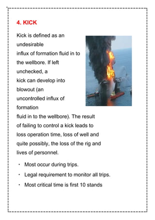
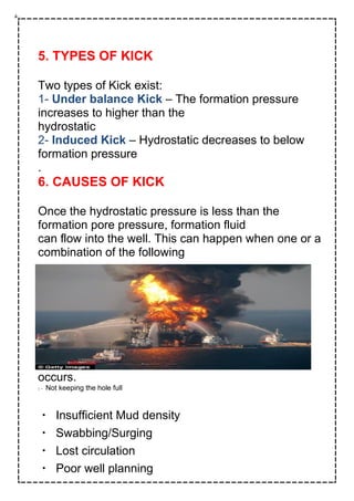
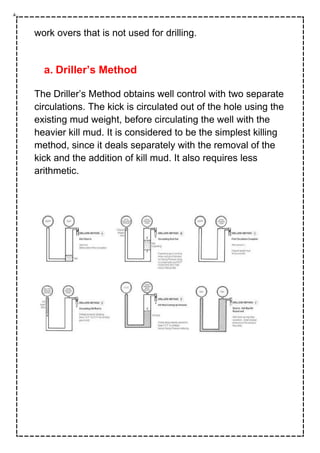
Republic of Iraq
Ministry of Higher Education
and Scientific Research
University of Kirkuk
College of Engineering
Petroleum Engineering Department
" The production"
The subject name:-Well control
Ahmed Qanbar Gani-nameStudent❖
Mohammed yashar-:Supervisor name
2020-Date:
1
TABLE OF CONTENTS
Page No.
1. Introduction
2. Objective
3. Well Control Theory
4. Kick
5. Types of Kick
6. Causes of Kick
7. Warning Signs of Kick
8. Recognition of Kick
9. Well Control Method
10. Importance of Well Control
11. Conclusion
.
WELL CONTROL
1. INTRODUCTION
The demand for energy is
constantly increasing,
forcing the
petroleum industry to
come up with
innovative solutions to
find and
produce the remaining
resources.
The industry is forced to
work in
remote locations where
high
pressure and temperature reservoirs,
deep water, narrow pressure
margins and harsh weather are
factors that hamper the operations.
The awareness regarding well
control in the drilling industry has
always been one of the main focus
areas. If formation fluid enter the
well it can lead to disastrous
blowouts where people on rigs can
be injured, or in a worst-case
scenario; killed. The environment
can also be harmed due to oil spills.
Moving drilling locations to remote areas around the
world demands the wells to be
drilled in the safest possible way.
Well control is the technique used in oil and gas
operations such as drilling, well work
over, and well completions to maintaining the fluid
column hydrostatic pressure and
formation pressure to prevent influx of formation
fluids into the wellbore. This
technique involves the estimation of formation fluid
pressures, the strength of the
subsurface formations and the use of casing and mud
density to offset those pressures
in a predictable fashion. Understanding of pressure
and pressure relationships are very important in well
control
2. OBJECTIVE
The objective of this assignment is to understand
the well control techniques used in
oil and gas operations such as drilling, well work
over and well completions.
What is
causing a kick to occur and how the signs can be
interpreted and understood.
The two
most common circulation methods, Driller’s- and
Wait & Weight Method have been
discussed.
3. WELL CONTROL THEORY
a. Primary Well Control
Primary well control is defined as the prevention
of formation fluid flow by
maintaining a hydrostatic pressure equal to or
greater than the pressure of the fluids in
the formation, but less than formation fracture
pressure. It is very important to make
sure that primary well control is preserved at all
times. This includes:
* Drilling fluids with adequate density are used.
* Active system volumes are continuously
monitored.
* Changes are detected immediately and correct
actions are being performed.
b. Secondary Well Control
If the pressure of our drilling fluid fails to prevent
formation fluid to enter the
wellbore, the well will flow. By the use of a
blowout preventer, (BOP), we can
prevent the fluids from escaping the well.
c. Hydrostatic Pressure
The hydrostatic pressure depends on the density and
vertical height of the fluid.
d. Circulation Pressure
Circulation pressure is given by the rig pump and
represents the total pressure
required to transfer mud from the pump, through the
surface lines, the drill string, the
bottom hole assembly,(BHA), the bit nozzles and up
through the annulus back to the surface
The annular pressure, or friction loss, helps in
preserving the pressure on the exposed
formation and causes a slight increase in the total
pressure as long as the pump is
circulating mud. This in turn leads to an increase in
the bottomhole pressure, (BHP),
above the static BHP. We can call this increase
annular pressure loss, (APL).
e. Bottomhole Pressure
BHP is the sum of all pressures being exerted on a
well by drilling personnel
operations. This means the sum of hydrostatic
pressures, APL plus any surface
applied back pressures.
f. Equivalent Circulating Density
The Equivalent Circulating Density, (ECD), can be
explained as an increase in
pressure that occurs only when the mud is being
circulated in the well. Due to the
friction in the annulus, the BHP will be higher than
when the mud is not being
circulated.
4. KICK
Kick is defined as an
undesirable
influx of formation fluid in to
the wellbore. If left
unchecked, a
kick can develop into
blowout (an
uncontrolled influx of
formation
fluid in to the wellbore). The result
of failing to control a kick leads to
loss operation time, loss of well and
quite possibly, the loss of the rig and
lives of personnel.
Most occur during trips.
Legal requirement to monitor all trips.
Most critical time is first 10 stands
5. TYPES OF KICK
Two types of Kick exist:
1- Under balance Kick – The formation pressure
increases to higher than the
hydrostatic
2- Induced Kick – Hydrostatic decreases to below
formation pressure
.
6. CAUSES OF KICK
Once the hydrostatic pressure is less than the
formation pore pressure, formation fluid
can flow into the well. This can happen when one or a
combination of the following
occurs.
l Not keeping the hole full
Insufficient Mud density
Swabbing/Surging
Lost circulation
Poor well planning
a. Not Keeping The Hole Full
When tripping out of the hole, the volume of the
steel pipe being removed results in a
corresponding decrease in wellbore fluid.
Whenever the fluid level in the hole
decreases, the hydrostatic pressure exerted by
the fluid also decreases and if the
decrease in hydrostatic pressure falls below the
formation pore pressure, the well may
flow. Therefore the hole must be filled to maintain
sufficient hydrostatic pressure to
control formation pressure. During tripping, the
pipe could be dry or wet depending
on the conditions. The API7G illustrates the
methodology for calculating accurate
pipe displacement and gives correct charts and
tables. To calculate the volume to fill
the well when tripping dry pipe out is given as:
Barrel to fill=pipe displacement (bbl/ft) × length pulled (ft)
Barrel to fill=(pipe displacement (bbls/ft) ÷ pipe
capacity (bbls/ft) )×length
pulled(ft)
In some wells, monitoring fill –up volumes on trips can
be complicated by loss
through perforations. The wells may stand full of fluid
initially, but over a period of a
period of time the fluid seeps in to the reservoir. In
such wells, the fill up volume will
always exceed the calculated or theoretical volume of
the steel removed from the
well. In some fields, wells have low reservoir
pressures and will not support a full
column of fluid. In these wells filling the hole with fluid
is essentially impossible
unless sort of bridging agent is used to temporarily
bridge off the subnormally
pressured zone. The common practice is to pump the
theoretical fill up volume while
pulling out of the well.
b. Insufficient Mud (Fluid) Density
The mud in the wellbore must exert enough
hydrostatic pressure to equal the
formation pore pressure. If the fluid’s hydrostatic
pressure is less than formation
pressure the well can flow. The most common reason
for insufficient fluid density is
drilling into unexpected abnormally pressured
formations. This situation usually
arises when unpredicted geological conditions are
encountered. Such as drilling
across a fault that abruptly changes the formation
being drilled. Mishandling mud at
the surface accounts for many instances of insufficient
fluid weight. Such as opening
wrong valve on the pump suction manifold and
allowing a tank of light weight fluid
to be pumped; bumping the water valve so more is
added than intended; washing off
shale shakers; or cleanup operations. All of these can
affect mud weight.
c. Swabbing / Surging
Swabbing is as a result of the upward movement of
pipe in a well and results in a
decrease in bottom hole pressure. In some cases, the
bottom hole pressure reduction
can be large enough to cause the well to go
underbalanced and allow formation fluids
to enter the wellbore. The initial swabbing action
compounded by the reduction in
hydrostatic pressure (from formation fluids entering
the well) can lead to a significant
reduction in bottom hole pressure and a larger influx
of formation fluids. Therefore,
early detection of swabbing on trips is critical to
minimizing the size of a kick. Many
wellbore conditions increase the likelihood of
swabbing on a trip. Swabbing (piston)
action is enhanced when pipe is pulled too fast. Poor
fluid properties, such as high
viscosity and gel strengths, also increase the chances
of swabbing a well in.
Additionally, large outside diameter (OD) tools
(packers, scrapers, fishing tools, etc.)
enhance the piston effect. These conditions need to
be recognized in order to decrease
the likelihood of swabbing a well in during
completion/work over operations. As
mentioned earlier, there are several computer and
calculator programs that can
estimate surge and swab pressures. Swabbing is
detected by closely monitoring hole
fill-up volumes during trips. For example, if three
barrels of steel (tubing) are
removed from the well and it takes only two barrels of
fluid to fill the hole, then a
one-barrel kick has probably been swabbed into the
wellbore. Special attention should
be paid to hole fill-up volumes since statistics indicate
that most kicks occur on trips.
d. Lost Circulation
Another cause of kick during completion/work over
operations is lost circulation.
Loss of circulation leads to a drop of both the fluid
level and hydrostatic pressure in a
well. If the hydrostatic pressure falls below the
reservoir pressure, the well kicks.
Three main causes of lost circulation are:
Excessive pressure overbalance
Excessive surge pressure
Poor formation integrity
i. Excessive Pressure Overbalance
It occurs when wellbore (bottom hole pressure)
pressures exceed the fracture pressure
of an exposed formation. If the fluid density of a
completion/work over fluid is too
high, the hydrostatic pressure in the well may exceed
the fracture pressure and result
in lost circulation. In these cases, loss of hydrostatic
pressure is minimized by
immediately pumping measured volumes of lighter
fluid into the well at the surface.
Another area of concern, when using fluid weights that
are close to the fracture
gradient, is equivalent circulating density (ECD). ECD
is the increase in bottom hole
pressure caused by friction. ECD can be quite large,
particularly when reverse
circulating, and can lead to lost circulation. In these
cases; the pump rate should be
maintained as low as possible to minimize wellbore
pressures and the possibility of
lost circulation.
ii. Excessive Surge Pressure
Surge pressure is the increase in bottom hole
pressure caused by the downward
movement of the work string. If the combination of this
surge pressure and
hydrostatic pressure exceeds the fracture pressure of
an exposed zone, loss of
circulation occurs. Therefore, surge pressures should
be minimized by monitoring trip
speed and return fluid volumes while running in the
well (especially with large
Outside Diameter (OD) tools like packers and
scrapers). There are several computer
and calculator packages that can estimate surge
pressures.
iii. Poor Formation Integrity:
If a well is completed in multiple zones or has shallow
holes in the casing, a weak
uphole zone can cause loss of circulation. In these
instances, maintenance of
hydrostatic pressure in a well is difficult and
sometimes requires the use of a bridging
agent to plug off the troublesome formation.
e. Poor Well Planning
The fourth cause of kick is poor well planning. The
mud and casing programs have a
great bearing on well control. These programs must
be flexible enough to allow
progressively deeper casing strings to be set;
otherwise a situation may arise where it is not
possible to control kicks or lost circulation. Well
control is an important part of well planning
7. WARNING SIGNS OF KICKS
Drilling Break. Always flow check.
Increase in flow returns
Pit gain
Incorrect trip volumes. Pressure may prevent mud
draining from the string.
Decrease in SPP or rise in SPM
Increasing gas values. CG , BG
Well flows with the pump off, Ballooning , Loss of
ECD, Charged fractures.
Change in mud properties. > Salinity may >
viscosity of mud > ECD
Increasing mud temperature
Cavings
Cutback in DxC or shale density
PWD
Gas cut mud expanding. 1200m bubble point.
Pinched bit, under gauge hole
Hook load/WOB variation, buoyancy
8. RECOGNITION OF KICK
Kicks don’t typically occur without
warning; the only time a kick
can
occur without warning is when
drilling offshore and there is no
annular connection between
the wellhead and the rig.
However,
there is never a lack of
indications
that a kick or blowout is occurring.
In the majority of situations the
borehole and mud pits are a closed
circulating system, the addition of
any fluid from the formation will
result in a change in return flow
and a change in the active pit
volume. Several types of flow meters can be used in the
operations, such as
Ultrasonic flow sensors and Coriolis flow sensors. However,
Coriolis type flow
meters are used by most for return-flow monitoring. It is
installed downstream of the
choke manifold. The key characteristic of the tool is its early
kick detection and
accurate of measurement of the flow rate coming from the
annular side. Field
experience has shown that ultrasonic flow meters are
unreliable because of the high
level of background noise. Because of its high accuracy and
immunity from external forces and the ease of installation,
the Coriolis-type meter is a reliable tool to take the flow
measurements. The Coriolis measuring principle operates
independently of the fluid physical properties, such as
viscosity and density. A kick can be detected quickly by
continuously monitoring and comparing when flow out
deviates from flow in. Trends are monitored through a data-
acquisition system. Alarms can be set, and, depending on
the system being used, the kick can be controlled
automatically. Downhole annular and bore pressures
acquired along the string through networked or wired pipe
(e.g. IntelliServ network) provide downhole information to
supplement surface data and improve early kick recognition
and analysis during
regaining control.
When any of the positive indications of a kick are observed
and a check shows that
the well is flowing, it should be shut-in immediately.
However, if the surface casing
alone has been set the flow should be diverted rather than
attempting a shut-in which
might endanger the rig. Once the well is shut-in on a kick
and control of the well is
established, preparations should be made to remove the
influx from the wellbore.
When preparing to remove the kick from the well, there are
some important
considerations that should be taken into account. These
considerations are valuable in
determining the proper well control method to use in
removing the kick from the wellbore and can be crucial to
maintaining control of the well during the kill
procedure. Some of the important kick handling concepts
includes:
 Determining reservoir pressure
 Identifying the type of kick
 Calculating and preparing kill weight fluid
 Circulating method considerations
 Killing a producing well
9. WELL CONTROL METHODS
During drilling operations, kicks are usually killed using the
Driller’s, Engineer’s or a combination of both called
Concurrent Method while forward circulating. The
selection of which to use will depend upon the amount and
type of kick fluids that have entered the well, the rig's
equipment capabilities, the minimum fracture pressure
in the open hole, and the drilling and operating companies
well control policies. For work over or completion
operations, other methods are often used. . Bull heading is a
common way to kill a well during workovers and completions
operations but is not often used for drilling operations.
Reverse circulation is another kill method used for
work overs that is not used for drilling.
a. Driller’s Method
The Driller’s Method obtains well control with two separate
circulations. The kick is circulated out of the hole using the
existing mud weight, before circulating the well with the
heavier kill mud. It is considered to be the simplest killing
method, since it deals separately with the removal of the
kick and the addition of kill mud. It also requires less
arithmetic.
The following steps describe
the Driller’s Method in detail:
1. When the kick is detected,
the well is shut in.
2. The Shut-in Drill pipe
Pressure, (SIDPP), and the
Shut-in Casing Pressure,
(SICP), are both recorded
before the pumps are
started. As the decreasing
well pressure can lead cause
more influx from the
formation, this operation
can be difficult. The choke
needs to be opened slowly
so the flow rate steadily
reaches the Slow Circulation Rate, (SCR).
3. The gas is being circulated out of the well, and the choke
pressure should be equal to SICP at the start. As the gas
expands towards the surface, the SICP value will reach its
top value just before the kick reaches the surface, before
decreasing to a value equal to SIDPP.
4. By using Equation 6, the kill weight mud is calculated.
5. As the drill pipe is filled with kill weight mud, SIDPP is
reduced to zero. As the heavier mud will increase the friction
pressure, the Initial Circulation Pressure, (ICP), will
decrease to Final Circulation Pressure, (FCP).
6. When the well has been filled with the heavy mud, the
well is closed and SIDPP and SICP are controlled. If the
well is killed, these values should be zero. If not, then:
a) There may be trapped pressure in the well
b) There may be an additional influx remaining in the well
c) There may not be dense enough kill weight fluid in the
well
b. Wait & Weight Method
The Wait & Weight Method, (W&W Method), is also known
as the Engineers Method. Compared to the Driller’s Method,
the W&W Method, in theory, only needs one circulation to
kill the well. As the well has been shut-in and the pressure is
stabilized, the SIDPP is used to calculate the kill weight
mud. As the mud is being pumped down the string, the
choke is adjusted to reduce the drill pipe pressure. The
static head of mud is balancing the formation pressure when
the mud reaches the bit. When finalizing the circulation, the
influx, drillpipe content and kill mud is being circulated to the
surface, the drillpipe pressure is kept constant at the
circulation pressure by choke adjustments.
The following steps describe the W&W Method in detail
1. The kick is detected and the well is shut in
2. After determining the SIDPP and SICP, the kill mud
weight should be calculated using Equation 6. As the
calculations are being made, gas might migrate up the
annulus causing an increase in the SICP, so attention needs
to be paid to the monitors.
3. When the kill mud is ready to be circulated, the pumps
are brought up to speed reaching SCR, while the choke is
being opened so that the casing pressure is maintained
constant.
4. When the kill weight mud reaches the bit, the drillpipe
pressure is equal to the
FCP.
5. The kill weight mud is circulated to the surface while
keeping a constant
FCP.22
6. After the kill mud has performed a circulation, the pumps
are stopped and the
well is shut in. Now, both the casing and drillpipe pressure
should be zero. In
not, the mud density was too low and another calculation
and circulation has
1. to be done.
c. Prevention Of Blowout
Alert and well trained crews
Knowledge on causes of kicks
Knowledge of warning signs
Shut-in responsibilities
Equipment
Trained crews to properly
operate equipment
10. IMPORTANCE OF WELL CONTROL
Provides a direct threat to the safety of the drilling rig
and its personnel.
Well control problems are costly in terms of time and
money.
Environmental Damage
Increased risk when drilling in unexplored areas with
unknown pressure regimes.
Prevention is always better than a cure.
Time is of the essence
11. CONCLUSIONS
The aim of oil operations is to complete all tasks in a safe
and efficient manner without detrimental effects to the
environment. This aim can only be achieved if control of the
well is maintained at all times. The understanding of
pressure and pressure relationships is important in
preventing blowouts. Experienced personnel that are able to
detect when the well is kicking and take proper and prompt
actions to
shut-in the well prevent blowouts.

Well control 1)

  • 1.
    Republic of Iraq Ministryof Higher Education and Scientific Research University of Kirkuk College of Engineering Petroleum Engineering Department " The production" The subject name:-Well control Ahmed Qanbar Gani-nameStudent❖ Mohammed yashar-:Supervisor name 2020-Date: 1
  • 2.
    TABLE OF CONTENTS PageNo. 1. Introduction 2. Objective 3. Well Control Theory 4. Kick 5. Types of Kick 6. Causes of Kick 7. Warning Signs of Kick 8. Recognition of Kick 9. Well Control Method 10. Importance of Well Control 11. Conclusion .
  • 3.
    WELL CONTROL 1. INTRODUCTION Thedemand for energy is constantly increasing, forcing the petroleum industry to come up with innovative solutions to find and produce the remaining resources. The industry is forced to work in remote locations where high pressure and temperature reservoirs, deep water, narrow pressure margins and harsh weather are factors that hamper the operations. The awareness regarding well control in the drilling industry has always been one of the main focus areas. If formation fluid enter the well it can lead to disastrous blowouts where people on rigs can be injured, or in a worst-case scenario; killed. The environment
  • 4.
    can also beharmed due to oil spills. Moving drilling locations to remote areas around the world demands the wells to be drilled in the safest possible way. Well control is the technique used in oil and gas operations such as drilling, well work over, and well completions to maintaining the fluid column hydrostatic pressure and formation pressure to prevent influx of formation fluids into the wellbore. This technique involves the estimation of formation fluid pressures, the strength of the subsurface formations and the use of casing and mud density to offset those pressures in a predictable fashion. Understanding of pressure and pressure relationships are very important in well control
  • 5.
    2. OBJECTIVE The objectiveof this assignment is to understand the well control techniques used in oil and gas operations such as drilling, well work over and well completions. What is causing a kick to occur and how the signs can be interpreted and understood. The two most common circulation methods, Driller’s- and Wait & Weight Method have been discussed.
  • 6.
    3. WELL CONTROLTHEORY a. Primary Well Control Primary well control is defined as the prevention of formation fluid flow by maintaining a hydrostatic pressure equal to or greater than the pressure of the fluids in the formation, but less than formation fracture pressure. It is very important to make sure that primary well control is preserved at all times. This includes: * Drilling fluids with adequate density are used. * Active system volumes are continuously monitored. * Changes are detected immediately and correct actions are being performed.
  • 7.
    b. Secondary WellControl If the pressure of our drilling fluid fails to prevent formation fluid to enter the wellbore, the well will flow. By the use of a blowout preventer, (BOP), we can prevent the fluids from escaping the well. c. Hydrostatic Pressure The hydrostatic pressure depends on the density and vertical height of the fluid. d. Circulation Pressure Circulation pressure is given by the rig pump and represents the total pressure required to transfer mud from the pump, through the surface lines, the drill string, the bottom hole assembly,(BHA), the bit nozzles and up through the annulus back to the surface The annular pressure, or friction loss, helps in preserving the pressure on the exposed formation and causes a slight increase in the total pressure as long as the pump is circulating mud. This in turn leads to an increase in the bottomhole pressure, (BHP),
  • 8.
    above the staticBHP. We can call this increase annular pressure loss, (APL). e. Bottomhole Pressure BHP is the sum of all pressures being exerted on a well by drilling personnel operations. This means the sum of hydrostatic pressures, APL plus any surface applied back pressures. f. Equivalent Circulating Density The Equivalent Circulating Density, (ECD), can be explained as an increase in pressure that occurs only when the mud is being circulated in the well. Due to the friction in the annulus, the BHP will be higher than when the mud is not being circulated.
  • 9.
    4. KICK Kick isdefined as an undesirable influx of formation fluid in to the wellbore. If left unchecked, a kick can develop into blowout (an uncontrolled influx of formation fluid in to the wellbore). The result of failing to control a kick leads to loss operation time, loss of well and quite possibly, the loss of the rig and lives of personnel. Most occur during trips. Legal requirement to monitor all trips. Most critical time is first 10 stands
  • 10.
    5. TYPES OFKICK Two types of Kick exist: 1- Under balance Kick – The formation pressure increases to higher than the hydrostatic 2- Induced Kick – Hydrostatic decreases to below formation pressure . 6. CAUSES OF KICK Once the hydrostatic pressure is less than the formation pore pressure, formation fluid can flow into the well. This can happen when one or a combination of the following occurs. l Not keeping the hole full Insufficient Mud density Swabbing/Surging Lost circulation Poor well planning
  • 11.
    a. Not KeepingThe Hole Full When tripping out of the hole, the volume of the steel pipe being removed results in a corresponding decrease in wellbore fluid. Whenever the fluid level in the hole decreases, the hydrostatic pressure exerted by the fluid also decreases and if the decrease in hydrostatic pressure falls below the formation pore pressure, the well may flow. Therefore the hole must be filled to maintain sufficient hydrostatic pressure to control formation pressure. During tripping, the pipe could be dry or wet depending on the conditions. The API7G illustrates the methodology for calculating accurate pipe displacement and gives correct charts and tables. To calculate the volume to fill the well when tripping dry pipe out is given as: Barrel to fill=pipe displacement (bbl/ft) × length pulled (ft)
  • 12.
    Barrel to fill=(pipedisplacement (bbls/ft) ÷ pipe capacity (bbls/ft) )×length pulled(ft) In some wells, monitoring fill –up volumes on trips can be complicated by loss through perforations. The wells may stand full of fluid initially, but over a period of a period of time the fluid seeps in to the reservoir. In such wells, the fill up volume will always exceed the calculated or theoretical volume of the steel removed from the well. In some fields, wells have low reservoir pressures and will not support a full column of fluid. In these wells filling the hole with fluid is essentially impossible unless sort of bridging agent is used to temporarily bridge off the subnormally pressured zone. The common practice is to pump the theoretical fill up volume while pulling out of the well.
  • 13.
    b. Insufficient Mud(Fluid) Density The mud in the wellbore must exert enough hydrostatic pressure to equal the formation pore pressure. If the fluid’s hydrostatic pressure is less than formation pressure the well can flow. The most common reason for insufficient fluid density is drilling into unexpected abnormally pressured formations. This situation usually arises when unpredicted geological conditions are encountered. Such as drilling across a fault that abruptly changes the formation being drilled. Mishandling mud at the surface accounts for many instances of insufficient fluid weight. Such as opening wrong valve on the pump suction manifold and allowing a tank of light weight fluid to be pumped; bumping the water valve so more is added than intended; washing off shale shakers; or cleanup operations. All of these can affect mud weight.
  • 14.
    c. Swabbing /Surging Swabbing is as a result of the upward movement of pipe in a well and results in a decrease in bottom hole pressure. In some cases, the bottom hole pressure reduction can be large enough to cause the well to go underbalanced and allow formation fluids to enter the wellbore. The initial swabbing action compounded by the reduction in hydrostatic pressure (from formation fluids entering the well) can lead to a significant reduction in bottom hole pressure and a larger influx of formation fluids. Therefore, early detection of swabbing on trips is critical to minimizing the size of a kick. Many wellbore conditions increase the likelihood of swabbing on a trip. Swabbing (piston) action is enhanced when pipe is pulled too fast. Poor fluid properties, such as high viscosity and gel strengths, also increase the chances of swabbing a well in. Additionally, large outside diameter (OD) tools (packers, scrapers, fishing tools, etc.)
  • 15.
    enhance the pistoneffect. These conditions need to be recognized in order to decrease the likelihood of swabbing a well in during completion/work over operations. As mentioned earlier, there are several computer and calculator programs that can estimate surge and swab pressures. Swabbing is detected by closely monitoring hole fill-up volumes during trips. For example, if three barrels of steel (tubing) are removed from the well and it takes only two barrels of fluid to fill the hole, then a one-barrel kick has probably been swabbed into the wellbore. Special attention should be paid to hole fill-up volumes since statistics indicate that most kicks occur on trips. d. Lost Circulation Another cause of kick during completion/work over operations is lost circulation. Loss of circulation leads to a drop of both the fluid level and hydrostatic pressure in a well. If the hydrostatic pressure falls below the reservoir pressure, the well kicks. Three main causes of lost circulation are: Excessive pressure overbalance Excessive surge pressure Poor formation integrity
  • 16.
    i. Excessive PressureOverbalance It occurs when wellbore (bottom hole pressure) pressures exceed the fracture pressure of an exposed formation. If the fluid density of a completion/work over fluid is too high, the hydrostatic pressure in the well may exceed the fracture pressure and result in lost circulation. In these cases, loss of hydrostatic pressure is minimized by immediately pumping measured volumes of lighter fluid into the well at the surface. Another area of concern, when using fluid weights that are close to the fracture gradient, is equivalent circulating density (ECD). ECD is the increase in bottom hole pressure caused by friction. ECD can be quite large, particularly when reverse circulating, and can lead to lost circulation. In these cases; the pump rate should be maintained as low as possible to minimize wellbore pressures and the possibility of lost circulation. ii. Excessive Surge Pressure Surge pressure is the increase in bottom hole pressure caused by the downward
  • 17.
    movement of thework string. If the combination of this surge pressure and hydrostatic pressure exceeds the fracture pressure of an exposed zone, loss of circulation occurs. Therefore, surge pressures should be minimized by monitoring trip speed and return fluid volumes while running in the well (especially with large Outside Diameter (OD) tools like packers and scrapers). There are several computer and calculator packages that can estimate surge pressures. iii. Poor Formation Integrity: If a well is completed in multiple zones or has shallow holes in the casing, a weak uphole zone can cause loss of circulation. In these instances, maintenance of hydrostatic pressure in a well is difficult and sometimes requires the use of a bridging agent to plug off the troublesome formation. e. Poor Well Planning The fourth cause of kick is poor well planning. The mud and casing programs have a great bearing on well control. These programs must be flexible enough to allow progressively deeper casing strings to be set; otherwise a situation may arise where it is not
  • 18.
    possible to controlkicks or lost circulation. Well control is an important part of well planning 7. WARNING SIGNS OF KICKS Drilling Break. Always flow check. Increase in flow returns Pit gain Incorrect trip volumes. Pressure may prevent mud draining from the string. Decrease in SPP or rise in SPM Increasing gas values. CG , BG Well flows with the pump off, Ballooning , Loss of ECD, Charged fractures. Change in mud properties. > Salinity may > viscosity of mud > ECD Increasing mud temperature Cavings Cutback in DxC or shale density PWD Gas cut mud expanding. 1200m bubble point. Pinched bit, under gauge hole Hook load/WOB variation, buoyancy
  • 19.
    8. RECOGNITION OFKICK Kicks don’t typically occur without warning; the only time a kick can occur without warning is when drilling offshore and there is no annular connection between the wellhead and the rig. However, there is never a lack of indications that a kick or blowout is occurring. In the majority of situations the borehole and mud pits are a closed circulating system, the addition of any fluid from the formation will result in a change in return flow and a change in the active pit volume. Several types of flow meters can be used in the operations, such as Ultrasonic flow sensors and Coriolis flow sensors. However, Coriolis type flow meters are used by most for return-flow monitoring. It is installed downstream of the choke manifold. The key characteristic of the tool is its early kick detection and accurate of measurement of the flow rate coming from the annular side. Field
  • 20.
    experience has shownthat ultrasonic flow meters are unreliable because of the high level of background noise. Because of its high accuracy and immunity from external forces and the ease of installation, the Coriolis-type meter is a reliable tool to take the flow measurements. The Coriolis measuring principle operates independently of the fluid physical properties, such as viscosity and density. A kick can be detected quickly by continuously monitoring and comparing when flow out deviates from flow in. Trends are monitored through a data- acquisition system. Alarms can be set, and, depending on the system being used, the kick can be controlled automatically. Downhole annular and bore pressures acquired along the string through networked or wired pipe (e.g. IntelliServ network) provide downhole information to supplement surface data and improve early kick recognition and analysis during regaining control. When any of the positive indications of a kick are observed and a check shows that the well is flowing, it should be shut-in immediately. However, if the surface casing alone has been set the flow should be diverted rather than attempting a shut-in which might endanger the rig. Once the well is shut-in on a kick and control of the well is established, preparations should be made to remove the influx from the wellbore. When preparing to remove the kick from the well, there are some important
  • 21.
    considerations that shouldbe taken into account. These considerations are valuable in determining the proper well control method to use in removing the kick from the wellbore and can be crucial to maintaining control of the well during the kill procedure. Some of the important kick handling concepts includes:  Determining reservoir pressure  Identifying the type of kick  Calculating and preparing kill weight fluid  Circulating method considerations  Killing a producing well 9. WELL CONTROL METHODS During drilling operations, kicks are usually killed using the Driller’s, Engineer’s or a combination of both called Concurrent Method while forward circulating. The selection of which to use will depend upon the amount and type of kick fluids that have entered the well, the rig's equipment capabilities, the minimum fracture pressure in the open hole, and the drilling and operating companies well control policies. For work over or completion operations, other methods are often used. . Bull heading is a common way to kill a well during workovers and completions operations but is not often used for drilling operations. Reverse circulation is another kill method used for
  • 22.
    work overs thatis not used for drilling. a. Driller’s Method The Driller’s Method obtains well control with two separate circulations. The kick is circulated out of the hole using the existing mud weight, before circulating the well with the heavier kill mud. It is considered to be the simplest killing method, since it deals separately with the removal of the kick and the addition of kill mud. It also requires less arithmetic.
  • 23.
    The following stepsdescribe the Driller’s Method in detail: 1. When the kick is detected, the well is shut in. 2. The Shut-in Drill pipe Pressure, (SIDPP), and the Shut-in Casing Pressure, (SICP), are both recorded before the pumps are started. As the decreasing well pressure can lead cause more influx from the formation, this operation can be difficult. The choke needs to be opened slowly so the flow rate steadily reaches the Slow Circulation Rate, (SCR). 3. The gas is being circulated out of the well, and the choke pressure should be equal to SICP at the start. As the gas expands towards the surface, the SICP value will reach its top value just before the kick reaches the surface, before decreasing to a value equal to SIDPP. 4. By using Equation 6, the kill weight mud is calculated. 5. As the drill pipe is filled with kill weight mud, SIDPP is reduced to zero. As the heavier mud will increase the friction pressure, the Initial Circulation Pressure, (ICP), will decrease to Final Circulation Pressure, (FCP).
  • 24.
    6. When thewell has been filled with the heavy mud, the well is closed and SIDPP and SICP are controlled. If the well is killed, these values should be zero. If not, then: a) There may be trapped pressure in the well b) There may be an additional influx remaining in the well c) There may not be dense enough kill weight fluid in the well b. Wait & Weight Method The Wait & Weight Method, (W&W Method), is also known as the Engineers Method. Compared to the Driller’s Method, the W&W Method, in theory, only needs one circulation to kill the well. As the well has been shut-in and the pressure is stabilized, the SIDPP is used to calculate the kill weight mud. As the mud is being pumped down the string, the choke is adjusted to reduce the drill pipe pressure. The static head of mud is balancing the formation pressure when the mud reaches the bit. When finalizing the circulation, the influx, drillpipe content and kill mud is being circulated to the surface, the drillpipe pressure is kept constant at the circulation pressure by choke adjustments.
  • 25.
    The following stepsdescribe the W&W Method in detail 1. The kick is detected and the well is shut in 2. After determining the SIDPP and SICP, the kill mud weight should be calculated using Equation 6. As the calculations are being made, gas might migrate up the annulus causing an increase in the SICP, so attention needs to be paid to the monitors. 3. When the kill mud is ready to be circulated, the pumps are brought up to speed reaching SCR, while the choke is being opened so that the casing pressure is maintained constant. 4. When the kill weight mud reaches the bit, the drillpipe pressure is equal to the FCP. 5. The kill weight mud is circulated to the surface while keeping a constant FCP.22 6. After the kill mud has performed a circulation, the pumps are stopped and the well is shut in. Now, both the casing and drillpipe pressure should be zero. In not, the mud density was too low and another calculation and circulation has 1. to be done.
  • 26.
    c. Prevention OfBlowout Alert and well trained crews Knowledge on causes of kicks Knowledge of warning signs Shut-in responsibilities Equipment Trained crews to properly operate equipment 10. IMPORTANCE OF WELL CONTROL Provides a direct threat to the safety of the drilling rig and its personnel. Well control problems are costly in terms of time and money. Environmental Damage Increased risk when drilling in unexplored areas with unknown pressure regimes. Prevention is always better than a cure. Time is of the essence
  • 27.
    11. CONCLUSIONS The aimof oil operations is to complete all tasks in a safe and efficient manner without detrimental effects to the environment. This aim can only be achieved if control of the well is maintained at all times. The understanding of pressure and pressure relationships is important in preventing blowouts. Experienced personnel that are able to detect when the well is kicking and take proper and prompt actions to shut-in the well prevent blowouts.