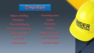
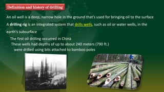
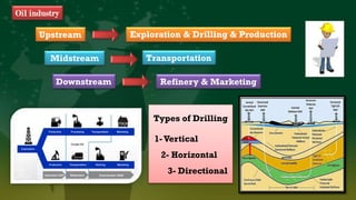
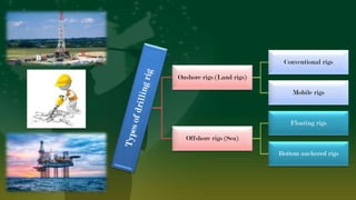
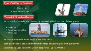
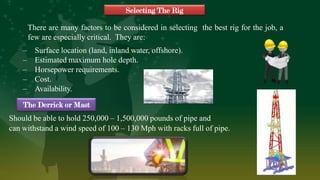
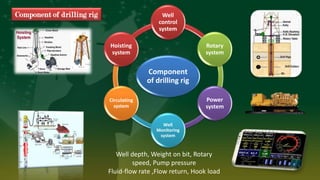
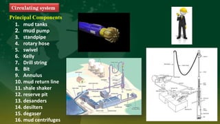
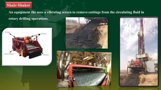
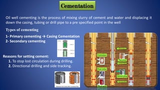
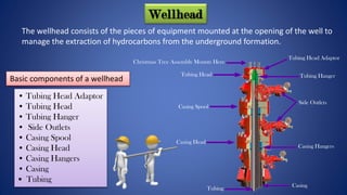
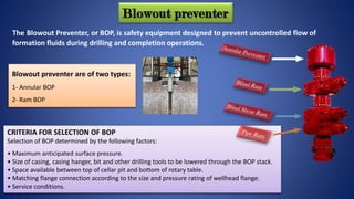
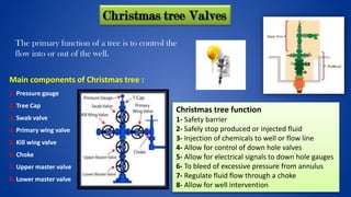
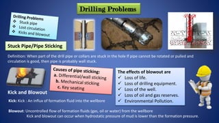
General Directorate of Institutes and Training
Hawler Institute for Oil & Gas
Department of Petroleum Institute (PETI)
Fifth Year – Group C
Shajwan Azad
Graduation Project
2019 – 2020
Academic year
These wells had depths of up to about 240 meters (790 ft.)
were drilled using bits attached to bamboo poles
An oil well is a deep, narrow hole in the ground that's used for bringing oil to the surface
A drilling rig is an integrated system that drills wells, such as oil or water wells, in the
earth's subsurface
The first oil drilling occurred in China
Definition and history of drilling
Midstream
Oil industry
Exploration & Drilling & Production
Refinery & Marketing
Types of Drilling
1-Vertical
2- Horizontal
3- Directional
Transportation
Upstream
Downstream
Onshore rigs (Land rigs)
Conventional rigs
Mobile rigs
Offshore rigs (Sea)
Floating rigs
Bottom anchored rigs
Types of drilling rig (offshore)
For most offshore wells, the types of rig required will fall into one of three groups
 Jack-ups
 Semi-Submersibles
 Drill Ships
Drill ships are used to drill the well in deep water ( up to 7000 ft. )
Semi-Submersibles are used mostly in the range of water depths from 100-600 m.
Jack-ups – where the water depth is less than 100m
Types of drilling rig (onshore)
 Conventional rigs
 Mobile rigs
– Surface location (land, inland water, offshore).
– Estimated maximum hole depth.
– Horsepower requirements.
– Cost.
– Availability.
Selecting The Rig
There are many factors to be considered in selecting the best rig for the job, a
few are especially critical. They are:
Should be able to hold 250,000 – 1,500,000 pounds of pipe and
can withstand a wind speed of 100 – 130 Mph with racks full of pipe.
The Derrick or Mast
Component
of drilling rig
Well
control
system
Rotary
system
Power
system
Well
Monitoring
system
Circulating
system
Hoisting
system
Well depth, Weight on bit, Rotary
speed, Pump pressure
Fluid-flow rate ,Flow return, Hook load
Component of drilling rig
Hoisting system
1. Draw works
2. Derrick
3. Crown block
4. Traveling block
5. Hook
6. Wire rope
The hoisting system is made up of the :
Drill pipe
API drill pipe Ranges :
Range Length (ft.)
1 18-22
2 27-30
3 38-45
Types of Drilling Bit
There are basically three types of drilling bit:
1. Drag Bits
2. Roller Cone Bits
3. Diamond Bits
Drag Bits
Roller Cone Bits
Diamond bits
Drag bits: used in soft formations such as sand or clay.
Diamond bit: used in hard formation
Roller cone bit: used in very soft formation to very hard formation.
Main functions and advantages Top drive system has 3 main functions:
- 1. Perform all normal hoisting requirements
- 2. Rotate the drill string
- 3. Enable circulation through the drill string Most
rigs today are equipped with top drive
TOP Drive
Rotary Table drive Drilling
Top Drive Drilling
The top drive rotates the drill string end bit without the use of a Kelly and
rotary table. The top drive is operated from a control console on the rig floor
Drilling Fluids
Three types of drilling mud are in common use:
 water-base mud
 oil-base mud
 Gas based fluids
 Bottom Hole Cleaning.
 Cuttings Transport.
 Bore Hole Wall Support/ Stabilization.
 Cooling The Bit.
 Hydraulic Power Transmission.
 Data Transmission (MWD).
 Reducing Friction.
 Corrosion Protection.
 Solid Suspension.
 Balancing Formation Pressure.
Functions
Principal Components
1. mud tanks
2. mud pump
3. standpipe
4. rotary hose
5. swivel
6. Kelly
7. Drill string
8. Bit
9. Annulus
10. mud return line
11. shale shaker
12. reserve pit
13. desanders
14. desilters
15. degaser
16. mud centrifuges
Circulating system
An equipment the uses a vibrating screen to remove cuttings from the circulating fluid in
rotary drilling operations.
Shale Shaker
Casing
Casing is large diameter pipe that is assembled and inserted into a recently drilled
section of a borehole.
Types of Casing Strings
1- Conductor casing
2- Surface casing
3- Intermediate casing
4- Production casing
5- Liners
36 in. OD
30 in. OD
24 in. OD, 20 in. OD
13 3/8 in. OD, 10 ¾ in. OD
9 5/8 in, OD, 7 ½ in. OD
5 ½ in. OD
4 ½ in. OD
4 in. OD
Where OD is Outside Diameter.
Available Casing Sizes :
Cementation
Oil well cementing is the process of mixing slurry of cement and water and displacing it
down the casing, tubing or drill pipe to a pre specified point in the well
1- Primary cementing → Casing Cementation
2- Secondary cementing
Types of cementing
Reasons for setting cement:
1. To stop lost circulation during drilling.
2. Directional drilling and side tracking.
Video (Cementation)
Video Link
https://www.youtube.com/watch?v=F75S-hd-QTE
• Tubing Head Adaptor
• Tubing Head
• Tubing Hanger
• Side Outlets
• Casing Spool
• Casing Head
• Casing Hangers
• Casing
• Tubing
Basic components of a wellhead
Wellhead
Tubing Head
Casing Spool
Casing Head
Tubing
Tubing Head Adaptor
Tubing Hanger
Casing Hangers
Casing
Christmas Tree Assembly Mounts Here
Side Outlets
The wellhead consists of the pieces of equipment mounted at the opening of the well to
manage the extraction of hydrocarbons from the underground formation.
Blowout preventer
The Blowout Preventer, or BOP, is safety equipment designed to prevent uncontrolled flow of
formation fluids during drilling and completion operations.
Blowout preventer are of two types:
1- Annular BOP
2- Ram BOP
CRITERIA FOR SELECTION OF BOP
Selection of BOP determined by the following factors:
• Maximum anticipated surface pressure.
• Size of casing, casing hanger, bit and other drilling tools to be lowered through the BOP stack.
• Space available between top of cellar pit and bottom of rotary table.
• Matching flange connection according to the size and pressure rating of wellhead flange.
• Service conditions.
Video (BOP)
Video Link
https://www.arescotx.com/photos-videos/what-is-a-blowout-preventer/
Main components of Christmas tree :
1. Pressure gauge
2. Tree Cap
3. Swab valve
4. Primary wing valve
5. Kill wing valve
6. Choke
7. Upper master valve
8. Lower master valve
Christmas tree Valves
Christmas tree function
1- Safety barrier
2- Safely stop produced or injected fluid
3- Injection of chemicals to well or flow line
4- Allow for control of down hole valves
5- Allow for electrical signals to down hole gauges
6- To bleed of excessive pressure from annulus
7- Regulate fluid flow through a choke
8- Allow for well intervention
The primary function of a tree is to control the
flow into or out of the well.
The effects of blowout are
 Loss of life.
 Loss of drilling equipment.
 Loss of the well.
 Loss of oil and gas reserves.
 Environmental Pollution.
Kick: Kick : An influx of formation fluid into the wellbore
Blowout: Uncontrolled flow of formation fluids (gas, oil or water) from the wellbore
Kick and blowout can occur when hydrostatic pressure of mud is lower than the formation pressure.
Kick and Blowout
Drilling Problems
Definition: When part of the drill pipe or collars are stuck in the hole If pipe cannot be rotated or pulled and
circulation is good, then pipe is probably wall stuck.
Stuck Pipe/Pipe Sticking
Graduation  Drilling Technology .pptx

Graduation Drilling Technology .pptx

  • 1.
    General Directorate ofInstitutes and Training Hawler Institute for Oil & Gas Department of Petroleum Institute (PETI) Fifth Year – Group C Shajwan Azad Graduation Project 2019 – 2020 Academic year
  • 3.
    These wells haddepths of up to about 240 meters (790 ft.) were drilled using bits attached to bamboo poles An oil well is a deep, narrow hole in the ground that's used for bringing oil to the surface A drilling rig is an integrated system that drills wells, such as oil or water wells, in the earth's subsurface The first oil drilling occurred in China Definition and history of drilling
  • 4.
    Midstream Oil industry Exploration &Drilling & Production Refinery & Marketing Types of Drilling 1-Vertical 2- Horizontal 3- Directional Transportation Upstream Downstream
  • 5.
    Onshore rigs (Landrigs) Conventional rigs Mobile rigs Offshore rigs (Sea) Floating rigs Bottom anchored rigs
  • 6.
    Types of drillingrig (offshore) For most offshore wells, the types of rig required will fall into one of three groups  Jack-ups  Semi-Submersibles  Drill Ships Drill ships are used to drill the well in deep water ( up to 7000 ft. ) Semi-Submersibles are used mostly in the range of water depths from 100-600 m. Jack-ups – where the water depth is less than 100m Types of drilling rig (onshore)  Conventional rigs  Mobile rigs
  • 7.
    – Surface location(land, inland water, offshore). – Estimated maximum hole depth. – Horsepower requirements. – Cost. – Availability. Selecting The Rig There are many factors to be considered in selecting the best rig for the job, a few are especially critical. They are: Should be able to hold 250,000 – 1,500,000 pounds of pipe and can withstand a wind speed of 100 – 130 Mph with racks full of pipe. The Derrick or Mast
  • 8.
    Component of drilling rig Well control system Rotary system Power system Well Monitoring system Circulating system Hoisting system Welldepth, Weight on bit, Rotary speed, Pump pressure Fluid-flow rate ,Flow return, Hook load Component of drilling rig
  • 9.
    Hoisting system 1. Drawworks 2. Derrick 3. Crown block 4. Traveling block 5. Hook 6. Wire rope The hoisting system is made up of the : Drill pipe API drill pipe Ranges : Range Length (ft.) 1 18-22 2 27-30 3 38-45
  • 10.
    Types of DrillingBit There are basically three types of drilling bit: 1. Drag Bits 2. Roller Cone Bits 3. Diamond Bits Drag Bits Roller Cone Bits Diamond bits Drag bits: used in soft formations such as sand or clay. Diamond bit: used in hard formation Roller cone bit: used in very soft formation to very hard formation.
  • 11.
    Main functions andadvantages Top drive system has 3 main functions: - 1. Perform all normal hoisting requirements - 2. Rotate the drill string - 3. Enable circulation through the drill string Most rigs today are equipped with top drive TOP Drive Rotary Table drive Drilling Top Drive Drilling The top drive rotates the drill string end bit without the use of a Kelly and rotary table. The top drive is operated from a control console on the rig floor
  • 12.
    Drilling Fluids Three typesof drilling mud are in common use:  water-base mud  oil-base mud  Gas based fluids  Bottom Hole Cleaning.  Cuttings Transport.  Bore Hole Wall Support/ Stabilization.  Cooling The Bit.  Hydraulic Power Transmission.  Data Transmission (MWD).  Reducing Friction.  Corrosion Protection.  Solid Suspension.  Balancing Formation Pressure. Functions
  • 13.
    Principal Components 1. mudtanks 2. mud pump 3. standpipe 4. rotary hose 5. swivel 6. Kelly 7. Drill string 8. Bit 9. Annulus 10. mud return line 11. shale shaker 12. reserve pit 13. desanders 14. desilters 15. degaser 16. mud centrifuges Circulating system
  • 14.
    An equipment theuses a vibrating screen to remove cuttings from the circulating fluid in rotary drilling operations. Shale Shaker
  • 15.
    Casing Casing is largediameter pipe that is assembled and inserted into a recently drilled section of a borehole. Types of Casing Strings 1- Conductor casing 2- Surface casing 3- Intermediate casing 4- Production casing 5- Liners 36 in. OD 30 in. OD 24 in. OD, 20 in. OD 13 3/8 in. OD, 10 ¾ in. OD 9 5/8 in, OD, 7 ½ in. OD 5 ½ in. OD 4 ½ in. OD 4 in. OD Where OD is Outside Diameter. Available Casing Sizes :
  • 16.
    Cementation Oil well cementingis the process of mixing slurry of cement and water and displacing it down the casing, tubing or drill pipe to a pre specified point in the well 1- Primary cementing → Casing Cementation 2- Secondary cementing Types of cementing Reasons for setting cement: 1. To stop lost circulation during drilling. 2. Directional drilling and side tracking.
  • 17.
  • 18.
    • Tubing HeadAdaptor • Tubing Head • Tubing Hanger • Side Outlets • Casing Spool • Casing Head • Casing Hangers • Casing • Tubing Basic components of a wellhead Wellhead Tubing Head Casing Spool Casing Head Tubing Tubing Head Adaptor Tubing Hanger Casing Hangers Casing Christmas Tree Assembly Mounts Here Side Outlets The wellhead consists of the pieces of equipment mounted at the opening of the well to manage the extraction of hydrocarbons from the underground formation.
  • 19.
    Blowout preventer The BlowoutPreventer, or BOP, is safety equipment designed to prevent uncontrolled flow of formation fluids during drilling and completion operations. Blowout preventer are of two types: 1- Annular BOP 2- Ram BOP CRITERIA FOR SELECTION OF BOP Selection of BOP determined by the following factors: • Maximum anticipated surface pressure. • Size of casing, casing hanger, bit and other drilling tools to be lowered through the BOP stack. • Space available between top of cellar pit and bottom of rotary table. • Matching flange connection according to the size and pressure rating of wellhead flange. • Service conditions.
  • 20.
  • 21.
    Main components ofChristmas tree : 1. Pressure gauge 2. Tree Cap 3. Swab valve 4. Primary wing valve 5. Kill wing valve 6. Choke 7. Upper master valve 8. Lower master valve Christmas tree Valves Christmas tree function 1- Safety barrier 2- Safely stop produced or injected fluid 3- Injection of chemicals to well or flow line 4- Allow for control of down hole valves 5- Allow for electrical signals to down hole gauges 6- To bleed of excessive pressure from annulus 7- Regulate fluid flow through a choke 8- Allow for well intervention The primary function of a tree is to control the flow into or out of the well.
  • 22.
    The effects ofblowout are  Loss of life.  Loss of drilling equipment.  Loss of the well.  Loss of oil and gas reserves.  Environmental Pollution. Kick: Kick : An influx of formation fluid into the wellbore Blowout: Uncontrolled flow of formation fluids (gas, oil or water) from the wellbore Kick and blowout can occur when hydrostatic pressure of mud is lower than the formation pressure. Kick and Blowout Drilling Problems Definition: When part of the drill pipe or collars are stuck in the hole If pipe cannot be rotated or pulled and circulation is good, then pipe is probably wall stuck. Stuck Pipe/Pipe Sticking