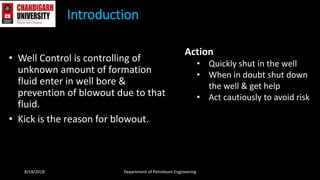
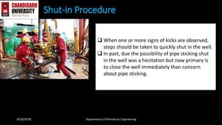
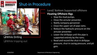
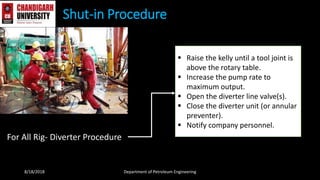
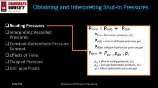
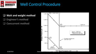
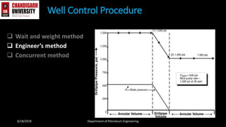
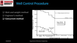
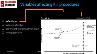
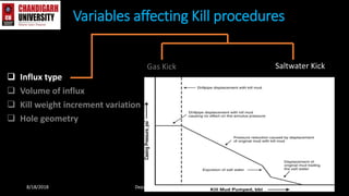
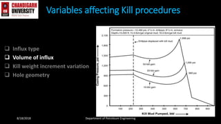
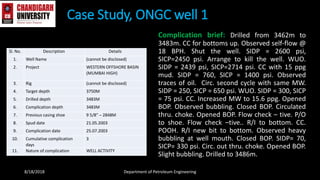
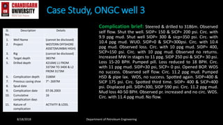
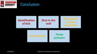
Project Topic:- Well Control & Blow out
Prevention
Mentor:
Dr. Saurabh Mishra
Assistant Professor & Head
Department of Petroleum
Engineering
Project Members-
Tarique Anwar 15BPE1003
Shamim Akram 15BPE1049
Marij Zama 15BPE1050
Astha Singh 15BPE1085
8/18/2018 Department of Petroleum Engineering
• Well Control is controlling of
unknown amount of formation
fluid enter in well bore &
prevention of blowout due to that
fluid.
• Kick is the reason for blowout.
Introduction
8/18/2018 Department of Petroleum Engineering
Action
• Quickly shut in the well
• When in doubt shut down
the well & get help
• Act cautiously to avoid risk
Kick
 When the formation pressure is greater than
the drilling fluid pressure, formation fluid enters
in the well which cause kick.
 If flow is controlled successfully than kick is
killed or uncontrolled kick result in blowout.
8/18/2018 Department of Petroleum Engineering
Kick
 Cause
 Significance
8/18/2018 Department of Petroleum Engineering
Kick
 Cause
o Insufficient mud weight.
o Improper hole fill-up during trips.
o Swabbing.
o Cut mud.
o Lost circulation
 Significance
8/18/2018 Department of Petroleum Engineering
Kick
 Cause
 Significance
o Flow rate increase.
o Pit volume increase.
o Flowing well with pumps off.
o Pump pressure decrease and pump stroke
increase.
o Improper hole fill-up on trips.
o String weight change.
o Drilling break.
o Cut mud weight
8/18/2018 Department of Petroleum Engineering
Shut-in Procedure
8/18/2018 Department of Petroleum Engineering
 When one or more signs of kicks are observed,
steps should be taken to quickly shut in the well.
 In past, due the possibility of pipe sticking shut
in the well was a hesitation but now primary is
to close the well immediately than concern
about pipe sticking.
While Drilling
While tripping out
Shut-in Procedure
Land/ Bottom Supported offshore
o RigRaise the Kelly until a tool joint is
above the rotary table
o Stop the mud pumps.
o Close the annular preventer.
o Notify company personnel.
o Read and record the shut-in drillpipe
pressure, the shut-in casing pressure, and
the pit gain.
8/18/2018 Department of Petroleum Engineering
While Drilling
While tripping out
Shut-in Procedure
Land/ Bottom Supported offshore
Floating Offshore Rigs
o Stop the mud pumps.
o Close the annular preventer.
o Notify company personnel.
o Close the upper set of pipe rams.
o Reduce the hydraulic pressure on the
annular preventer.
o Lower the drillpipe until the pipe is
supported entirely by the rams.
o Read and record the shut-in drillpipe
pressure, shut-in casing pressure, and pit
gain.
8/18/2018 Department of Petroleum Engineering
While Drilling
While tripping out
Shut-in Procedure
Land/ Bottom Supported offshore
o Set the top tool joint on the slips.
o Install and make up a full-opening, fully
opened safety valve on the drillpipe.
o Close the safety valve and the annular
preventer.
o Notify company personnel.
o Pick up and make up the kelly.
o Open the safety valve.
o Read and record the shut-in drillpipe
pressure, shut-in casing pressure, and pit
gain.
8/18/2018 Department of Petroleum Engineering
While Drilling
While tripping out
Shut-in Procedure
Land/ Bottom Supported offshore
Floating Offshore Rigs
o Set the top tool joint on the slips.
o Install and make up a full-opening, fully
opened safety valve in the drillpipe.
o Close the safety valve and the annular
preventer.
o Notify company personnel.
o Pick up and make up the kelly.
o Reduce the hydraulic pressure on the
annular preventer.
o Lower the drillpipe until the rams support it.
o Read and record the shut-in drillpipe
pressure, shut-in casing pressure, and pit
gain.8/18/2018 Department of Petroleum Engineering
Shut-in Procedure
For All Rig- Diverter Procedure
 Raise the kelly until a tool joint is
above the rotary table.
 Increase the pump rate to
maximum output.
 Open the diverter line valve(s).
 Close the diverter unit (or annular
preventer).
 Notify company personnel.
8/18/2018 Department of Petroleum Engineering
Reading Pressures
Interpreting Recorded
Pressures
Constant-Bottomhole-Pressure
Concept
Effects of Time
Trapped Pressure
Drill pipe Floats
Obtaining and Interpreting Shut-In Pressures
8/18/2018 Department of Petroleum Engineering
Pform = Psidp + Pdph
Pform- Formation pressure, psi;
Psidp – shut in drill pipe pressure, psi;
Pdph- drillpipe hydrostatic pressure,psi
Pform = Psic + pah + pi
psic = shut-in casing pressure, psi;
pah = annular-hydrostatic pressure, psi;
pi = influx-hydrostatic pressure, psi.
Reading Pressures
Interpreting Recorded
Pressures
Constant-Bottomhole-Pressure
Concept
Effects of Time
Trapped Pressure
Drill pipe Floats
Obtaining and Interpreting Shut-In Pressures
8/18/2018 Department of Petroleum Engineering
• formation pressure (pform) is
greater than the drillpipe
hydrostatic pressure by an
amount equal to the psidp
• Drill pipe pressure is bottom
hole pressure, casing pressure
can not consider as bottom
hole pressure due the
formation fluid in annulus
Reading Pressures
Interpreting Recorded
Pressures
Constant-Bottomhole-Pressure
Concept
Effects of Time
Trapped Pressure
Drill pipe Floats
Obtaining and Interpreting Shut-In Pressures
8/18/2018 Department of Petroleum Engineering
• Drill pipe pressure is greater
than the formation pressure,
certain amount of pressure
needs to balance by mud
pressure.
• If drill pipe pressure is slightly
greater or equal to the
formation pressure than it is
constant bottom hole pressure.
Reading Pressures
Interpreting Recorded
Pressures
Constant-Bottomhole-Pressure
Concept
Effects of Time
Trapped Pressure
Drill pipe Floats
Obtaining and Interpreting Shut-In Pressures
8/18/2018 Department of Petroleum Engineering
Reading Pressures
Interpreting Recorded
Pressures
Constant-Bottomhole-Pressure
Concept
Effects of Time
Trapped Pressure
Drill pipe Floats
Obtaining and Interpreting Shut-In Pressures
8/18/2018 Department of Petroleum Engineering
• Trapped pressure is greater
than the amount needed to
control the bottom hole
pressure
• Improper trapped pressure is
very difficult to kill
Reading Pressures
Interpreting Recorded
Pressures
Constant-Bottomhole-Pressure
Concept
Effects of Time
Trapped Pressure
Drill pipe Floats
Obtaining and Interpreting Shut-In Pressures
8/18/2018 Department of Petroleum Engineering
• When float valve is used a kick
can occur
• Float valve prevents fluid and
pressure through drill pipe
• Psidp = pΣ + pkr
• Pkr = PΣ - Psidp
• where pkr = pump pressure at kill rate, psi,
and pΣ = total pressure, psi
Influx Gradient
Kill Mud Weight
Kick Calculation
8/18/2018 Department of Petroleum Engineering
gi = influx gradient, psi/ft;
gmdp = mud gradient in drillpipe, psi/ft;
hi = influx height, ft
Influx Gradient
Kill Mud Weight
Kick Calculation
8/18/2018 Department of Petroleum Engineering
ρkw = kill-mud weight, lbm/gal;
19.23 = conversion constant;
Dtv = true vertical-bit depth, ft;
ρo = original mud weight, lbm/gal.
Well Control Equipment
8/18/2018 Department of Petroleum Engineering
• BOP
Annular Type
Ram Type
Well Control Equipment
8/18/2018 Department of Petroleum Engineering
Accumulator
Well Control Equipment
8/18/2018 Department of Petroleum Engineering
BOP Control Panel
 Wait and weight method
 Engineer’s method
 Concurrent method
Well Control Procedure
8/18/2018 Department of Petroleum Engineering
 Wait and weight method
 Engineer’s method
 Concurrent method
Well Control Procedure
8/18/2018 Department of Petroleum Engineering
 Wait and weight method
 Engineer’s method
 Concurrent method
Well Control Procedure
8/18/2018 Department of Petroleum Engineering
 Influx type
 Volume of influx
 Kill weight increment variation
 Hole geometry
Variables affecting Kill procedures
8/18/2018 Department of Petroleum Engineering
Gas Kick Saltwater Kick
 Influx type
 Volume of influx
 Kill weight increment variation
 Hole geometry
Variables affecting Kill procedures
8/18/2018 Department of Petroleum Engineering
Gas Kick Saltwater Kick
 Influx type
 Volume of influx
 Kill weight increment variation
 Hole geometry
Variables affecting Kill procedures
8/18/2018 Department of Petroleum Engineering
 Influx type
 Volume of influx
 Kill weight increment variation
 Hole geometry
Variables affecting Kill procedures
8/18/2018 Department of Petroleum Engineering
 Influx type
 Volume of influx
 Kill weight increment variation
 Hole geometry
Variables affecting Kill procedures
8/18/2018 Department of Petroleum Engineering
Prerecorded data
Kick data
Kill mud data
Pump pressure
Kill Sheet
8/18/2018 Department of Petroleum Engineering
Complication brief: Drilled from 3462m to
3483m. CC for bottoms up. Observed self-flow @
18 BPH. Shut the well. SIDP = 2600 psi,
SICP=2450 psi. Arrange to kill the well. WUO.
SIDP = 2439 psi, SICP=2714 psi. CC with 15 ppg
mud. SIDP = 760, SICP = 1400 psi. Observed
traces of oil. Circ. second cycle with same MW.
SIDP = 250, SICP = 650 psi. WUO. SIDP = 300, SICP
= 75 psi. CC. Increased MW to 15.6 ppg. Opened
BOP. Observed bubbling. Closed BOP. Circulated
thru. choke. Opened BOP. Flow check – tive. P/O
to shoe. Flow check –tive.. R/I to bottom. CC.
POOH. R/I new bit to bottom. Observed heavy
bubbling at well mouth. Closed BOP. SIDP= 70,
SICP= 330 psi. Circ. out thru. choke. Opened BOP.
Slight bubbling. Drilled to 3486m.
Case Study, ONGC well 1
8/18/2018 Department of Petroleum Engineering
Sl. No. Description Details
1. Well Name (cannot be disclosed)
2. Project WESTERN OFFSHORE BASIN
(MUMBAI HIGH)
3. Rig (cannot be disclosed)
4. Target depth 3750M
5. Drilled depth 3483M
6. Complication depth 3483M
7. Previous casing shoe 9 5/8” – 2848M
8. Spud date 21.05.2003
9. Complication date 25.07.2003
10. Cumulative complication
days
3
11. Nature of complication WELL ACTIVITY
Complication brief: Lowered 9 5/8” casing with shoe at
1971.6m. Carried out cementation. During WOC observed gas
bubbling from annulus. Ann. Pr. rose to 356 psi. Closed BOP. Bleed
pr. Pr. rose from 150 to 348 psi and stabilised. Bleed pr. Pumped 19
bbl 14 ppg mud. Closed well. Ann. Pr 24 psi. Observed gas and little
flow of mud. Pumped 20 bbl 14 ppg mud. WUO. Ann. Pr. 279 psi.
Pumped 12 ppg mud in ann. in stages with max. pr of 350 psi. Bleed
to 200 psi. WUO. Pr. 239 psi.. Pumped 12 ppg mud with max. pr.
350 psi. Pr. dropped to 320 psi. Bleed to 200 psi. WUO. Ann. Pr 247
psi. Bleed off. Opened BOP. Set slip. Connected BOP. Pumped 4 bbl
12 ppg mud. Scrapped well to 1940m. Increased MW to 12 ppg.
Recorded logs from 1730m to 1250m. Perforated casing in the
interval 1363.5m to 1364.1m. Tried to establish circ. behind casing
but failed. Injectivity 1 BPM. Perforated at 1310 to 1311m. Tried to
establish circ. but failed. Observed flow from annulus @ 2 LPM.
Closed BOP. Bleed pr. from 265 to 80 psi. Carried out injectivity and
sq. cement. After WOC bleed pr. from ann. and casing. No flow.
Drilled out cement from 1257m to 1324m and tested casing OK.
Cleared to 1945m. Tested casing. OK.
Case Study, ONGC well 2
8/18/2018 Department of Petroleum Engineering
Sl.
No.
Description Details
1. Well Name (cannot be disclosed)
2. Project WESTERN OFFSHORE
ASSET(MUMBAI HIGH)
3. Rig (cannot be disclosed)
4. Target depth 3175M
5. Drilled depth 1972M
6. Complication depth 1972M
7. Previous casing shoe 9 5/8” – 1971.6M
8. Spud date 19.05.2003
9. Complication date 07.07.2003
10. Cumulative
complication days
17
11. Nature of
complication
ANNULUS WELL
ACTIVITY
Complication brief: Steered & drilled to 3186m. Observed
self flow. Shut the well. SIDP= 150 & SICP= 200 psi. Circ. with
9.9 ppg mud. Shut well SIDP= 300 & sicp=350 psi. Circ. with
10.4 ppg mud. WUO. SIDP=0 & SICP=300psi. Circ. with 10.4
ppg mud. Observed loss. Circ. with 10 ppg mud. SIDP= 400,
SICP=150 psi. Circ. with 10 ppg mud. Observed no returns.
Increased MW in stages to 11 ppg. SIDP 250 psi & SICP= 30 psi.
Loss 15-20 BPH. Pumped pill. Loss reduced to 18 BPH. Circ.
with 11 ppg mud. SIDP=30 psi, SICP= 0 psi. Opened BOP. WOS
no success. Observed self flow. Circ. 11.2 ppg mud. Pumped
HSD & pipe lax. WOS, no success. Spotted again. SIDP=400 &
SICP 175 psi. Circ. Spotted third time. SIDP= 400 & SICP=400
psi. Displaced pill. SIDP=300, SIDP 590 psi. Circ. 11.2 ppg mud.
Mud loss 40-50 BPH. Observed pr. increased and no circ. WOS.
Circ. with 11.4 ppg mud. No flow.
Case Study, ONGC well 3
8/18/2018 Department of Petroleum Engineering
Sl.
No.
Description Details
1. Well Name (cannot be disclosed)
2. Project WESTERN OFFSHORE
ASSET(MUMBAI HIGH)
3. Rig (cannot be disclosed)
4. Target depth 3837M
5. Drilled depth 4216M( L1 FROM
3373M TO 3400 & L2
FROM 3173M
6. Complication depth 3186M
7. Previous casing shoe 7”- 2697M
8. Spud date
9. Complication date 07.06.2003
10. Cumulative
complication days
16
11. Nature of
complication
ACTIVITY & LOSS.
Conclusion
8/18/2018 Department of Petroleum Engineering
Identification
of kick
Shut in the
well
Kick type &
pressure
calculation
Kill mud data
Pump
pressure
1. petrowiki.org/PEH:Well_Control:_Pr
ocedures_and_Principles
2. www.spe.org/en/jpt/jpt-article-
detail/?art=2244
3. ONGC Hand book, well control and
pressure calculations
References
8/18/2018 Department of Petroleum Engineering

Well control and blowout preventer

  • 1.
    Project Topic:- WellControl & Blow out Prevention Mentor: Dr. Saurabh Mishra Assistant Professor & Head Department of Petroleum Engineering Project Members- Tarique Anwar 15BPE1003 Shamim Akram 15BPE1049 Marij Zama 15BPE1050 Astha Singh 15BPE1085 8/18/2018 Department of Petroleum Engineering
  • 2.
    • Well Controlis controlling of unknown amount of formation fluid enter in well bore & prevention of blowout due to that fluid. • Kick is the reason for blowout. Introduction 8/18/2018 Department of Petroleum Engineering Action • Quickly shut in the well • When in doubt shut down the well & get help • Act cautiously to avoid risk
  • 3.
    Kick  When theformation pressure is greater than the drilling fluid pressure, formation fluid enters in the well which cause kick.  If flow is controlled successfully than kick is killed or uncontrolled kick result in blowout. 8/18/2018 Department of Petroleum Engineering
  • 4.
    Kick  Cause  Significance 8/18/2018Department of Petroleum Engineering
  • 5.
    Kick  Cause o Insufficientmud weight. o Improper hole fill-up during trips. o Swabbing. o Cut mud. o Lost circulation  Significance 8/18/2018 Department of Petroleum Engineering
  • 6.
    Kick  Cause  Significance oFlow rate increase. o Pit volume increase. o Flowing well with pumps off. o Pump pressure decrease and pump stroke increase. o Improper hole fill-up on trips. o String weight change. o Drilling break. o Cut mud weight 8/18/2018 Department of Petroleum Engineering
  • 7.
    Shut-in Procedure 8/18/2018 Departmentof Petroleum Engineering  When one or more signs of kicks are observed, steps should be taken to quickly shut in the well.  In past, due the possibility of pipe sticking shut in the well was a hesitation but now primary is to close the well immediately than concern about pipe sticking.
  • 8.
    While Drilling While trippingout Shut-in Procedure Land/ Bottom Supported offshore o RigRaise the Kelly until a tool joint is above the rotary table o Stop the mud pumps. o Close the annular preventer. o Notify company personnel. o Read and record the shut-in drillpipe pressure, the shut-in casing pressure, and the pit gain. 8/18/2018 Department of Petroleum Engineering
  • 9.
    While Drilling While trippingout Shut-in Procedure Land/ Bottom Supported offshore Floating Offshore Rigs o Stop the mud pumps. o Close the annular preventer. o Notify company personnel. o Close the upper set of pipe rams. o Reduce the hydraulic pressure on the annular preventer. o Lower the drillpipe until the pipe is supported entirely by the rams. o Read and record the shut-in drillpipe pressure, shut-in casing pressure, and pit gain. 8/18/2018 Department of Petroleum Engineering
  • 10.
    While Drilling While trippingout Shut-in Procedure Land/ Bottom Supported offshore o Set the top tool joint on the slips. o Install and make up a full-opening, fully opened safety valve on the drillpipe. o Close the safety valve and the annular preventer. o Notify company personnel. o Pick up and make up the kelly. o Open the safety valve. o Read and record the shut-in drillpipe pressure, shut-in casing pressure, and pit gain. 8/18/2018 Department of Petroleum Engineering
  • 11.
    While Drilling While trippingout Shut-in Procedure Land/ Bottom Supported offshore Floating Offshore Rigs o Set the top tool joint on the slips. o Install and make up a full-opening, fully opened safety valve in the drillpipe. o Close the safety valve and the annular preventer. o Notify company personnel. o Pick up and make up the kelly. o Reduce the hydraulic pressure on the annular preventer. o Lower the drillpipe until the rams support it. o Read and record the shut-in drillpipe pressure, shut-in casing pressure, and pit gain.8/18/2018 Department of Petroleum Engineering
  • 12.
    Shut-in Procedure For AllRig- Diverter Procedure  Raise the kelly until a tool joint is above the rotary table.  Increase the pump rate to maximum output.  Open the diverter line valve(s).  Close the diverter unit (or annular preventer).  Notify company personnel. 8/18/2018 Department of Petroleum Engineering
  • 13.
    Reading Pressures Interpreting Recorded Pressures Constant-Bottomhole-Pressure Concept Effectsof Time Trapped Pressure Drill pipe Floats Obtaining and Interpreting Shut-In Pressures 8/18/2018 Department of Petroleum Engineering Pform = Psidp + Pdph Pform- Formation pressure, psi; Psidp – shut in drill pipe pressure, psi; Pdph- drillpipe hydrostatic pressure,psi Pform = Psic + pah + pi psic = shut-in casing pressure, psi; pah = annular-hydrostatic pressure, psi; pi = influx-hydrostatic pressure, psi.
  • 14.
    Reading Pressures Interpreting Recorded Pressures Constant-Bottomhole-Pressure Concept Effectsof Time Trapped Pressure Drill pipe Floats Obtaining and Interpreting Shut-In Pressures 8/18/2018 Department of Petroleum Engineering • formation pressure (pform) is greater than the drillpipe hydrostatic pressure by an amount equal to the psidp • Drill pipe pressure is bottom hole pressure, casing pressure can not consider as bottom hole pressure due the formation fluid in annulus
  • 15.
    Reading Pressures Interpreting Recorded Pressures Constant-Bottomhole-Pressure Concept Effectsof Time Trapped Pressure Drill pipe Floats Obtaining and Interpreting Shut-In Pressures 8/18/2018 Department of Petroleum Engineering • Drill pipe pressure is greater than the formation pressure, certain amount of pressure needs to balance by mud pressure. • If drill pipe pressure is slightly greater or equal to the formation pressure than it is constant bottom hole pressure.
  • 16.
    Reading Pressures Interpreting Recorded Pressures Constant-Bottomhole-Pressure Concept Effectsof Time Trapped Pressure Drill pipe Floats Obtaining and Interpreting Shut-In Pressures 8/18/2018 Department of Petroleum Engineering
  • 17.
    Reading Pressures Interpreting Recorded Pressures Constant-Bottomhole-Pressure Concept Effectsof Time Trapped Pressure Drill pipe Floats Obtaining and Interpreting Shut-In Pressures 8/18/2018 Department of Petroleum Engineering • Trapped pressure is greater than the amount needed to control the bottom hole pressure • Improper trapped pressure is very difficult to kill
  • 18.
    Reading Pressures Interpreting Recorded Pressures Constant-Bottomhole-Pressure Concept Effectsof Time Trapped Pressure Drill pipe Floats Obtaining and Interpreting Shut-In Pressures 8/18/2018 Department of Petroleum Engineering • When float valve is used a kick can occur • Float valve prevents fluid and pressure through drill pipe • Psidp = pΣ + pkr • Pkr = PΣ - Psidp • where pkr = pump pressure at kill rate, psi, and pΣ = total pressure, psi
  • 19.
    Influx Gradient Kill MudWeight Kick Calculation 8/18/2018 Department of Petroleum Engineering gi = influx gradient, psi/ft; gmdp = mud gradient in drillpipe, psi/ft; hi = influx height, ft
  • 20.
    Influx Gradient Kill MudWeight Kick Calculation 8/18/2018 Department of Petroleum Engineering ρkw = kill-mud weight, lbm/gal; 19.23 = conversion constant; Dtv = true vertical-bit depth, ft; ρo = original mud weight, lbm/gal.
  • 21.
    Well Control Equipment 8/18/2018Department of Petroleum Engineering • BOP Annular Type Ram Type
  • 22.
    Well Control Equipment 8/18/2018Department of Petroleum Engineering Accumulator
  • 23.
    Well Control Equipment 8/18/2018Department of Petroleum Engineering BOP Control Panel
  • 24.
     Wait andweight method  Engineer’s method  Concurrent method Well Control Procedure 8/18/2018 Department of Petroleum Engineering
  • 25.
     Wait andweight method  Engineer’s method  Concurrent method Well Control Procedure 8/18/2018 Department of Petroleum Engineering
  • 26.
     Wait andweight method  Engineer’s method  Concurrent method Well Control Procedure 8/18/2018 Department of Petroleum Engineering
  • 27.
     Influx type Volume of influx  Kill weight increment variation  Hole geometry Variables affecting Kill procedures 8/18/2018 Department of Petroleum Engineering Gas Kick Saltwater Kick
  • 28.
     Influx type Volume of influx  Kill weight increment variation  Hole geometry Variables affecting Kill procedures 8/18/2018 Department of Petroleum Engineering Gas Kick Saltwater Kick
  • 29.
     Influx type Volume of influx  Kill weight increment variation  Hole geometry Variables affecting Kill procedures 8/18/2018 Department of Petroleum Engineering
  • 30.
     Influx type Volume of influx  Kill weight increment variation  Hole geometry Variables affecting Kill procedures 8/18/2018 Department of Petroleum Engineering
  • 31.
     Influx type Volume of influx  Kill weight increment variation  Hole geometry Variables affecting Kill procedures 8/18/2018 Department of Petroleum Engineering
  • 32.
    Prerecorded data Kick data Killmud data Pump pressure Kill Sheet 8/18/2018 Department of Petroleum Engineering
  • 33.
    Complication brief: Drilledfrom 3462m to 3483m. CC for bottoms up. Observed self-flow @ 18 BPH. Shut the well. SIDP = 2600 psi, SICP=2450 psi. Arrange to kill the well. WUO. SIDP = 2439 psi, SICP=2714 psi. CC with 15 ppg mud. SIDP = 760, SICP = 1400 psi. Observed traces of oil. Circ. second cycle with same MW. SIDP = 250, SICP = 650 psi. WUO. SIDP = 300, SICP = 75 psi. CC. Increased MW to 15.6 ppg. Opened BOP. Observed bubbling. Closed BOP. Circulated thru. choke. Opened BOP. Flow check – tive. P/O to shoe. Flow check –tive.. R/I to bottom. CC. POOH. R/I new bit to bottom. Observed heavy bubbling at well mouth. Closed BOP. SIDP= 70, SICP= 330 psi. Circ. out thru. choke. Opened BOP. Slight bubbling. Drilled to 3486m. Case Study, ONGC well 1 8/18/2018 Department of Petroleum Engineering Sl. No. Description Details 1. Well Name (cannot be disclosed) 2. Project WESTERN OFFSHORE BASIN (MUMBAI HIGH) 3. Rig (cannot be disclosed) 4. Target depth 3750M 5. Drilled depth 3483M 6. Complication depth 3483M 7. Previous casing shoe 9 5/8” – 2848M 8. Spud date 21.05.2003 9. Complication date 25.07.2003 10. Cumulative complication days 3 11. Nature of complication WELL ACTIVITY
  • 34.
    Complication brief: Lowered9 5/8” casing with shoe at 1971.6m. Carried out cementation. During WOC observed gas bubbling from annulus. Ann. Pr. rose to 356 psi. Closed BOP. Bleed pr. Pr. rose from 150 to 348 psi and stabilised. Bleed pr. Pumped 19 bbl 14 ppg mud. Closed well. Ann. Pr 24 psi. Observed gas and little flow of mud. Pumped 20 bbl 14 ppg mud. WUO. Ann. Pr. 279 psi. Pumped 12 ppg mud in ann. in stages with max. pr of 350 psi. Bleed to 200 psi. WUO. Pr. 239 psi.. Pumped 12 ppg mud with max. pr. 350 psi. Pr. dropped to 320 psi. Bleed to 200 psi. WUO. Ann. Pr 247 psi. Bleed off. Opened BOP. Set slip. Connected BOP. Pumped 4 bbl 12 ppg mud. Scrapped well to 1940m. Increased MW to 12 ppg. Recorded logs from 1730m to 1250m. Perforated casing in the interval 1363.5m to 1364.1m. Tried to establish circ. behind casing but failed. Injectivity 1 BPM. Perforated at 1310 to 1311m. Tried to establish circ. but failed. Observed flow from annulus @ 2 LPM. Closed BOP. Bleed pr. from 265 to 80 psi. Carried out injectivity and sq. cement. After WOC bleed pr. from ann. and casing. No flow. Drilled out cement from 1257m to 1324m and tested casing OK. Cleared to 1945m. Tested casing. OK. Case Study, ONGC well 2 8/18/2018 Department of Petroleum Engineering Sl. No. Description Details 1. Well Name (cannot be disclosed) 2. Project WESTERN OFFSHORE ASSET(MUMBAI HIGH) 3. Rig (cannot be disclosed) 4. Target depth 3175M 5. Drilled depth 1972M 6. Complication depth 1972M 7. Previous casing shoe 9 5/8” – 1971.6M 8. Spud date 19.05.2003 9. Complication date 07.07.2003 10. Cumulative complication days 17 11. Nature of complication ANNULUS WELL ACTIVITY
  • 35.
    Complication brief: Steered& drilled to 3186m. Observed self flow. Shut the well. SIDP= 150 & SICP= 200 psi. Circ. with 9.9 ppg mud. Shut well SIDP= 300 & sicp=350 psi. Circ. with 10.4 ppg mud. WUO. SIDP=0 & SICP=300psi. Circ. with 10.4 ppg mud. Observed loss. Circ. with 10 ppg mud. SIDP= 400, SICP=150 psi. Circ. with 10 ppg mud. Observed no returns. Increased MW in stages to 11 ppg. SIDP 250 psi & SICP= 30 psi. Loss 15-20 BPH. Pumped pill. Loss reduced to 18 BPH. Circ. with 11 ppg mud. SIDP=30 psi, SICP= 0 psi. Opened BOP. WOS no success. Observed self flow. Circ. 11.2 ppg mud. Pumped HSD & pipe lax. WOS, no success. Spotted again. SIDP=400 & SICP 175 psi. Circ. Spotted third time. SIDP= 400 & SICP=400 psi. Displaced pill. SIDP=300, SIDP 590 psi. Circ. 11.2 ppg mud. Mud loss 40-50 BPH. Observed pr. increased and no circ. WOS. Circ. with 11.4 ppg mud. No flow. Case Study, ONGC well 3 8/18/2018 Department of Petroleum Engineering Sl. No. Description Details 1. Well Name (cannot be disclosed) 2. Project WESTERN OFFSHORE ASSET(MUMBAI HIGH) 3. Rig (cannot be disclosed) 4. Target depth 3837M 5. Drilled depth 4216M( L1 FROM 3373M TO 3400 & L2 FROM 3173M 6. Complication depth 3186M 7. Previous casing shoe 7”- 2697M 8. Spud date 9. Complication date 07.06.2003 10. Cumulative complication days 16 11. Nature of complication ACTIVITY & LOSS.
  • 36.
    Conclusion 8/18/2018 Department ofPetroleum Engineering Identification of kick Shut in the well Kick type & pressure calculation Kill mud data Pump pressure
  • 37.
    1. petrowiki.org/PEH:Well_Control:_Pr ocedures_and_Principles 2. www.spe.org/en/jpt/jpt-article- detail/?art=2244 3.ONGC Hand book, well control and pressure calculations References 8/18/2018 Department of Petroleum Engineering