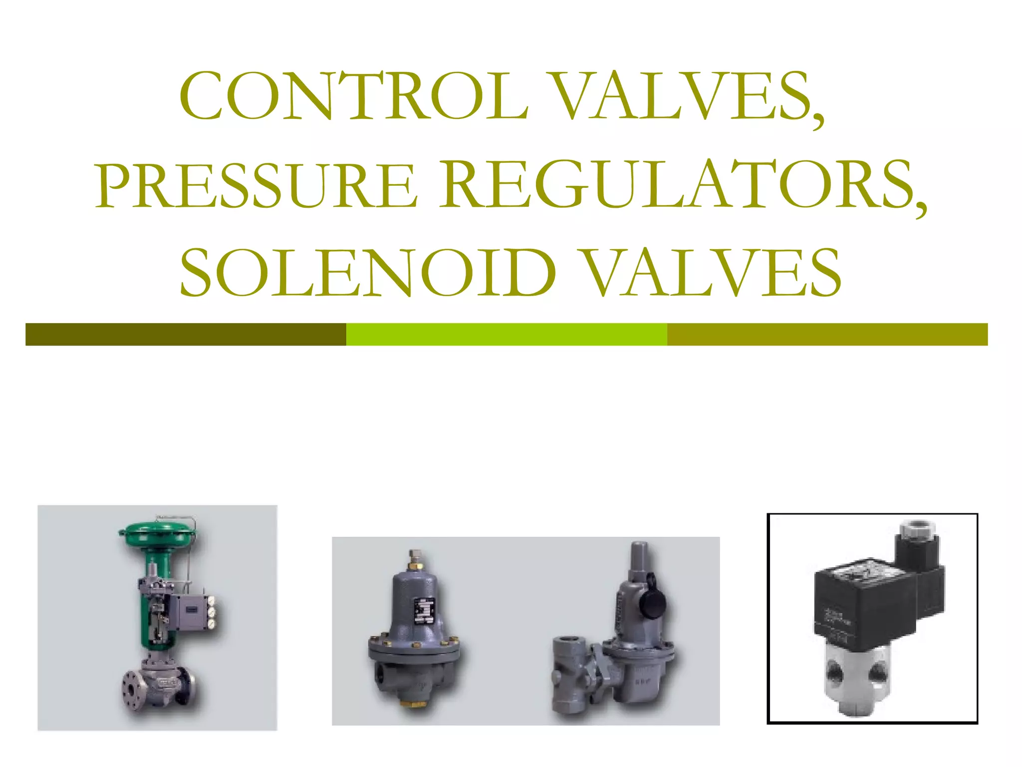
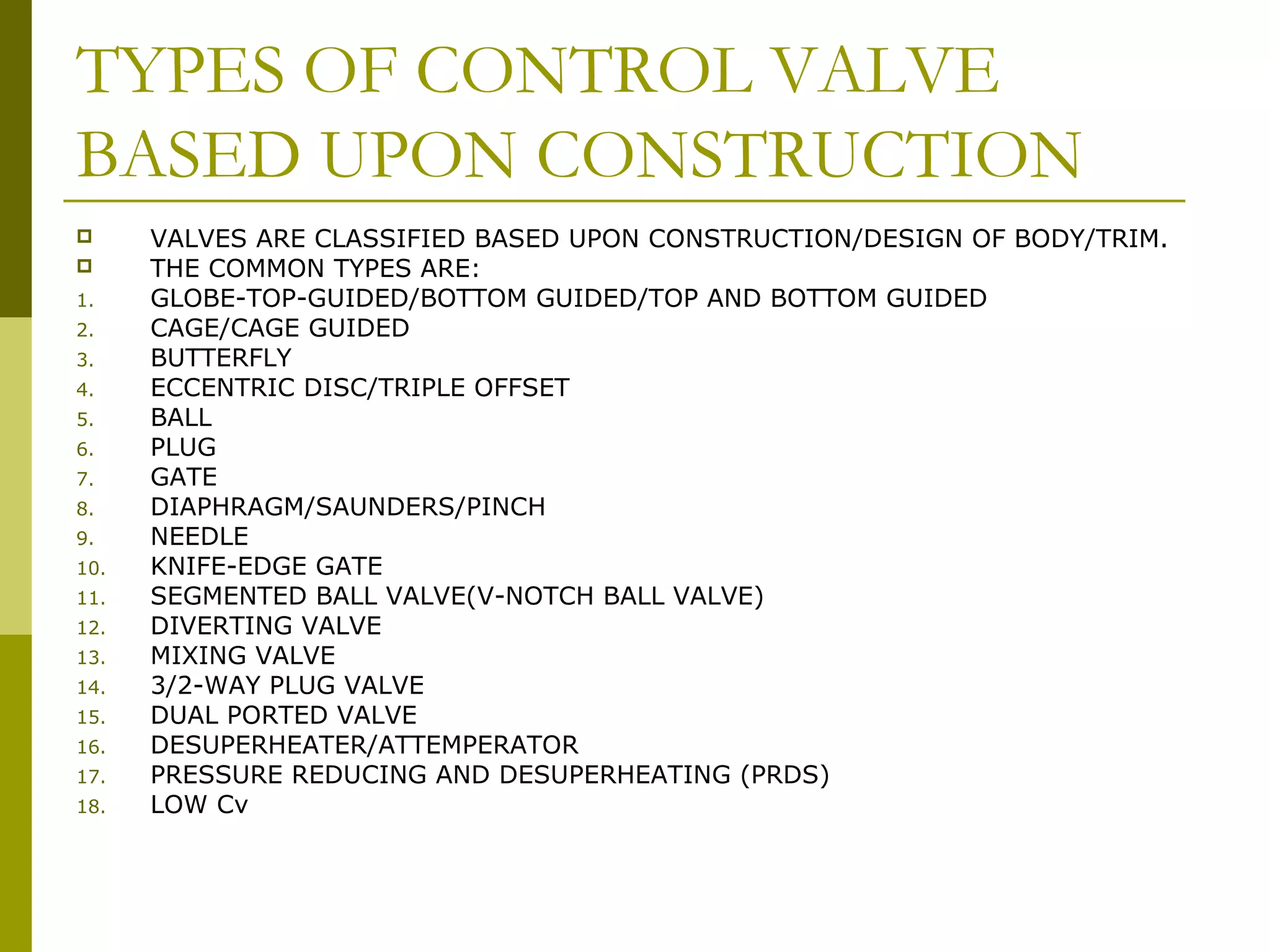
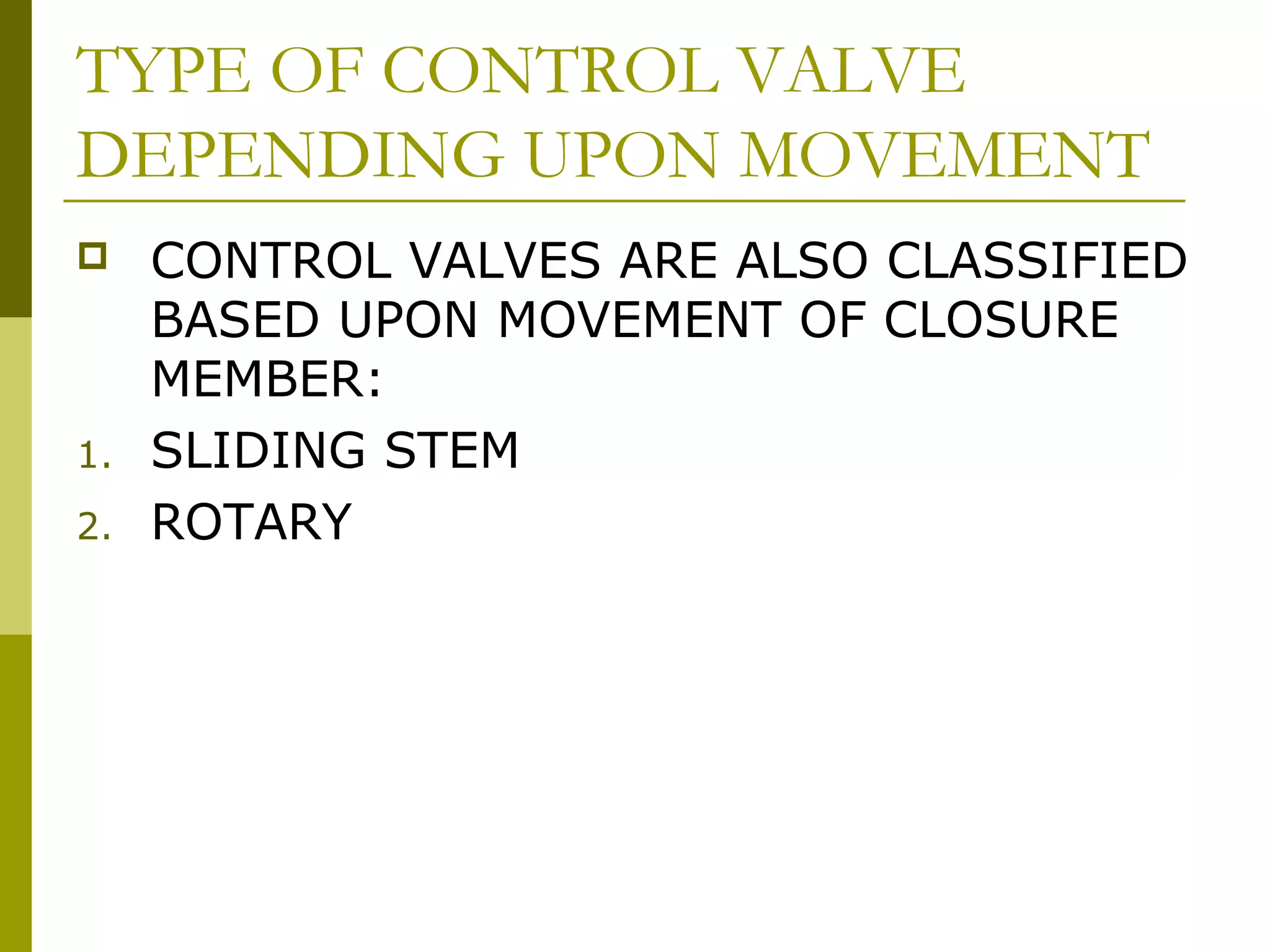
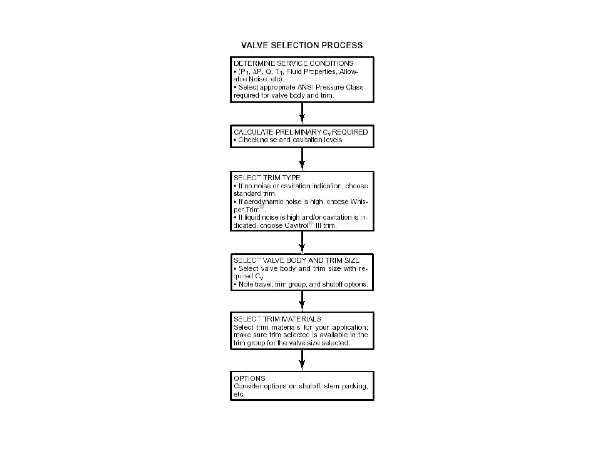
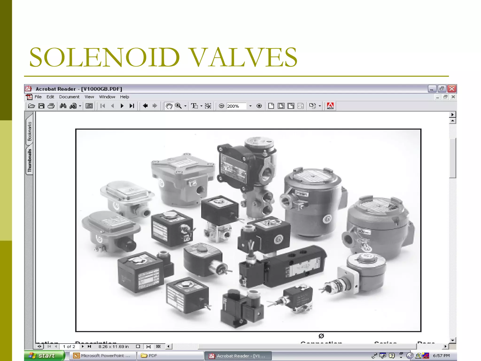
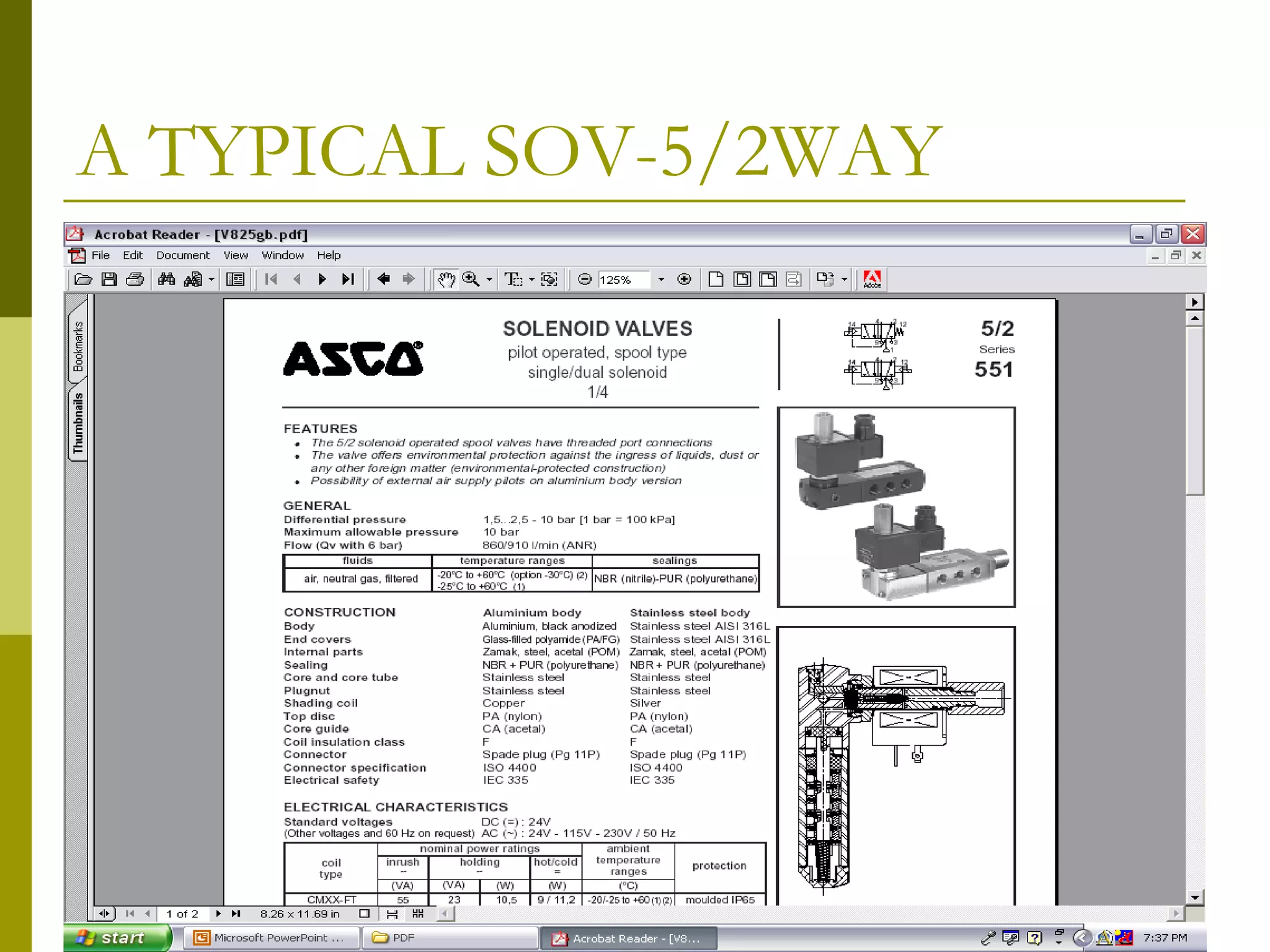
This document provides an overview of control valves, pressure regulators, and solenoid valves. It defines a control valve as a final control element used to manipulate flow for process control. It describes various types of control valves based on control action, flow characteristics, construction, and movement. Pressure regulating valves are designed to maintain a set pressure. Solenoid valves use an electric solenoid to switch ports and are commonly used as control accessories.
In this day and age of automated computer control valve sizing, the logic and theories behind it are invisible. In his presentation, Al Holton of Allagash Valve & Controls will look at the basic principles that apply and how they affect the application and installation of a wide range of control valve types. He will also review the reasoning behind valve type selection.
What Is A Control Valve
Process Control Terminology
Sliding-Stem Control Valve Terminology
Rotary-Shaft Control Valve Terminology
Control Valve Functions and Characteristics Terminology
Other Process Control Terminology
sliding stem control valve
Control Valves types, control valves characterstics, affects on control valves due to various process fluctuations or cavitations or flashing and remidies.The model datasheets also included.
A Control Valve is the most commonly used
final control element used to regulate fluid flow in
a process. In a process, normally it is the only
controllable element residing in the loop.
Ø This is a device used to modulate flow of
process fluid in pipe lines by creating a variable
area in the flow path.
Ø The flow path is varied with respect to the
control signal received from the controller
towards the required flow modulation.
Setpoint Integrated Solutions is an industry leader in applying Control Valve solutions across industry segments.
Brannon Gant - Regional Sales Manager
Split Range Control - Greg McMillan DeminarJim Cahill
Presented March 9, 2011 by Greg McMillan as on-line demo/seminar. Video recording available at: http://www.screencast.com/users/JimCahill/folders/Public
PROYECTO EMPLEO DE UNA TURBINA DE VAPOR, ACTUALMENTE FUERA DE SERVICIO, PARA GENERAR ENERGÍA ELÉCTRICA CONJUNTAMENTE CON UNA MÁQUINA ASINCRÓNICA NUEVA
SE EMPLEARIAN RECURSOS EXISTENTES TALES COMO UNA TURBINA DE
VAPOR, ACTUALMENTE FUERA DE SERVICIO, CON ALIMENTACIÓN EN
600# Y 150#, MONTADA EN SU BASE ORIGINAL, EN LA EX PLANTA DE
BUTADIENO, CON CAPACIDAD DE GENERACIÓN APROXIMADA DE 4
MW.
EN ESTE TRABAJO SE PROPONE UNA SOLUCION DE BAJO COSTO COMPARATIVO QUE PERMITIRIA LA OPTIMIZACION DEL BALANCE DE VAPOR E INCREMENTARIA LA CONFIABILIDAD DEL SISTEMA
Unit 1-introduction to Mechanisms, Kinematics of machines of VTU Syllabus prepared by Hareesha N Gowda, Asst. Prof, Dayananda Sagar College of Engg, Blore. Please write to hareeshang@gmail.com for suggestions and criticisms.
A control valve is a power-operated device used to regulate or manipulate the flow of fluids, such as gas, oil, water, and steam. It is a critical part of a control loop and is an example of a final control element.
How to Calculate Pump Flow Rate: A Step-by-Step Guide
Pump flow rate is a crucial parameter to consider when choosing or specifying a sanitary pump. It tells us how much liquid the pump can move in a certain amount of time and is usually expressed in gallons per minute (gpm), liters per second (l/s), or cubic meters per hour (m³/h).
Why is pump flow rate important?
Let’s say you have a pump that needs to move 100 gallons of water per minute. But the pump can only move 60 gallons per minute. This means that the pump is working at 60% capacity.
Now, let’s say you have another pump that can move 150 gallons per minute. This pump is around 67% utilized if it’s only moving 100 gallons per minute.
As such, knowing how to calculate pump flow rate can help you:
Choose a pump that is more efficient for your needs
Assess if your existing system is working efficiently
Operate your pump at or near its best efficiency point (BEP)
A pump’s BEP is the point at which it produces the most flow with the least amount of power. You don’t want to operate a pump that isn’t powerful enough to meet your needs or one that consumes more energy than necessary.
Worse, failing to operate your pump at its BEP increases the pump’s chance of failure.
Now that we know why pump flow rate is important, let’s learn how to calculate it.
1 – Use Manufacturer-Provided Pump Curves
While there are several ways to calculate pump flow rate, using pump curves is one of the most common. A pump curve goes by several names, including:
Pump selection curve
Pump efficiency curve
Pump performance curve
Pump curves include a range of performance metrics, such as:
Flow rate (measured in gpm, l/s, or m/h)
Pressure (PSI)
Head (feet or meters)
Power consumption (horsepower or kilowatts)
Impeller trim/diameter (inches)
If you’ve already established some of these metrics, you can use a pump curve to find a pump that meets your desired flow rate. Here’s an example of how you can use pump curves to select a pump.
Say you’re considering a TF-C100 Centrifugal Pump (whose chart is shown above). You’ve picked out the one with a 3.5″ impeller diameter that operates at 1 horsepower.
Assuming that you need the pump to move fluid up 40 feet (head), you’ll:
Look up your desired head in feet along the chart’s vertical (Y) axis
Run your finger/ruler straight along the 40-foot mark
Mark the point where the 3.5” impeller diameter curve interacts with your finger/ruler
Check the corresponding value on the chart’s horizontal (X) axis
That value, 40 gallons per minute in our case, is the pump’s flow rate given our set of conditions
It’s worth noting that other factors (discussed towards the end of this article) can influence your pump’s actual flow rate, including:
Fluid viscosity
Fluid temperature
Suction and discharge pipe sizes
Therefore, it’s advisable to get in touch with the pump experts at Sanitary Fittings if you’d like help reading the pump selection curves tailored for your operation.
Flow Rate L
A List of Steps to Shortlist Solenoid Valve based on Your Desired Technical S...Das Services Inc
A Solenoid valve works as an electromechanical gadget with a current which is going through the coil present in the valve. This current flow results in the expansion of a magnetic field utilized in controlling the flow of gas as well as liquid.
Here are a few points that you should be kept in mind while shortlisting a solenoid valve.
Precision Unleashed: Perfect Control Valves - Aeliya MarineAeliya Marine Tech
Explore lineup of control valves for automation - expertly engineered for unparalleled quality and reliability. Find the perfect product to elevate your project's performance and efficiency
Micro piv measurements for hydrodynamic characterizations of microfluidic flowsSadiq Rahim
The application presented here is based on a non-invasive method for velocity measurements in micro channels.
A micro PIV measurement system is used to obtain velocity profile distributions in primary flow domain and in vortex zone.
Experimental data is compared to data from numerical simulations.
If both data are consistent to each other, it gives information about vortical structures.
Student information management system project report ii.pdfKamal Acharya
Our project explains about the student management. This project mainly explains the various actions related to student details. This project shows some ease in adding, editing and deleting the student details. It also provides a less time consuming process for viewing, adding, editing and deleting the marks of the students.
NO1 Uk best vashikaran specialist in delhi vashikaran baba near me online vas...Amil Baba Dawood bangali
Contact with Dawood Bhai Just call on +92322-6382012 and we'll help you. We'll solve all your problems within 12 to 24 hours and with 101% guarantee and with astrology systematic. If you want to take any personal or professional advice then also you can call us on +92322-6382012 , ONLINE LOVE PROBLEM & Other all types of Daily Life Problem's.Then CALL or WHATSAPP us on +92322-6382012 and Get all these problems solutions here by Amil Baba DAWOOD BANGALI
#vashikaranspecialist #astrologer #palmistry #amliyaat #taweez #manpasandshadi #horoscope #spiritual #lovelife #lovespell #marriagespell#aamilbabainpakistan #amilbabainkarachi #powerfullblackmagicspell #kalajadumantarspecialist #realamilbaba #AmilbabainPakistan #astrologerincanada #astrologerindubai #lovespellsmaster #kalajaduspecialist #lovespellsthatwork #aamilbabainlahore#blackmagicformarriage #aamilbaba #kalajadu #kalailam #taweez #wazifaexpert #jadumantar #vashikaranspecialist #astrologer #palmistry #amliyaat #taweez #manpasandshadi #horoscope #spiritual #lovelife #lovespell #marriagespell#aamilbabainpakistan #amilbabainkarachi #powerfullblackmagicspell #kalajadumantarspecialist #realamilbaba #AmilbabainPakistan #astrologerincanada #astrologerindubai #lovespellsmaster #kalajaduspecialist #lovespellsthatwork #aamilbabainlahore #blackmagicforlove #blackmagicformarriage #aamilbaba #kalajadu #kalailam #taweez #wazifaexpert #jadumantar #vashikaranspecialist #astrologer #palmistry #amliyaat #taweez #manpasandshadi #horoscope #spiritual #lovelife #lovespell #marriagespell#aamilbabainpakistan #amilbabainkarachi #powerfullblackmagicspell #kalajadumantarspecialist #realamilbaba #AmilbabainPakistan #astrologerincanada #astrologerindubai #lovespellsmaster #kalajaduspecialist #lovespellsthatwork #aamilbabainlahore #Amilbabainuk #amilbabainspain #amilbabaindubai #Amilbabainnorway #amilbabainkrachi #amilbabainlahore #amilbabaingujranwalan #amilbabainislamabad
Industrial Training at Shahjalal Fertilizer Company Limited (SFCL)MdTanvirMahtab2
This presentation is about the working procedure of Shahjalal Fertilizer Company Limited (SFCL). A Govt. owned Company of Bangladesh Chemical Industries Corporation under Ministry of Industries.
Immunizing Image Classifiers Against Localized Adversary Attacksgerogepatton
This paper addresses the vulnerability of deep learning models, particularly convolutional neural networks
(CNN)s, to adversarial attacks and presents a proactive training technique designed to counter them. We
introduce a novel volumization algorithm, which transforms 2D images into 3D volumetric representations.
When combined with 3D convolution and deep curriculum learning optimization (CLO), itsignificantly improves
the immunity of models against localized universal attacks by up to 40%. We evaluate our proposed approach
using contemporary CNN architectures and the modified Canadian Institute for Advanced Research (CIFAR-10
and CIFAR-100) and ImageNet Large Scale Visual Recognition Challenge (ILSVRC12) datasets, showcasing
accuracy improvements over previous techniques. The results indicate that the combination of the volumetric
input and curriculum learning holds significant promise for mitigating adversarial attacks without necessitating
adversary training.
CFD Simulation of By-pass Flow in a HRSG module by R&R Consult.pptxR&R Consult
CFD analysis is incredibly effective at solving mysteries and improving the performance of complex systems!
Here's a great example: At a large natural gas-fired power plant, where they use waste heat to generate steam and energy, they were puzzled that their boiler wasn't producing as much steam as expected.
R&R and Tetra Engineering Group Inc. were asked to solve the issue with reduced steam production.
An inspection had shown that a significant amount of hot flue gas was bypassing the boiler tubes, where the heat was supposed to be transferred.
R&R Consult conducted a CFD analysis, which revealed that 6.3% of the flue gas was bypassing the boiler tubes without transferring heat. The analysis also showed that the flue gas was instead being directed along the sides of the boiler and between the modules that were supposed to capture the heat. This was the cause of the reduced performance.
Based on our results, Tetra Engineering installed covering plates to reduce the bypass flow. This improved the boiler's performance and increased electricity production.
It is always satisfying when we can help solve complex challenges like this. Do your systems also need a check-up or optimization? Give us a call!
Work done in cooperation with James Malloy and David Moelling from Tetra Engineering.
More examples of our work https://www.r-r-consult.dk/en/cases-en/
2. WHAT IS A CONTROL VALVE?
A CONTROL VALVE IS A FINAL CONTROL
ELEMENT IN A PROCESS CONTROL LOOP
TYPICALLY USED TO MANIPULATE FLOW
OF MATERIAL WITH AN OBJECTIVE TO
ATTAIN A DESIRED VALUE OF THE
CONTROLLED PROCESS VARIABLE. THIS
IS ACHIEVED BY THROTTLING FLOW OF
MATERIAL BY OPERATING A CLOSURE
MEMBER WHICH CLOSES THE VALVE’S
PORT, PARTIALLY OR FULLY.
3. CONTROL VALVE SIZING
CONTROL VALVE SIZING IS THE PROCESS
OF DETERMINATION OF REQUIRED FLOW
CAPACITY OF A VALVE FOR A GIVEN
SERVICE
4. TYPES OF CONTROL VALVES
CONTROL VALVES MAY BE CLASSIFIED
INTO DIFFERENT TYPES BASED UPON :
1. TYPE OF CONTROL ACTION
2. TYPE OF FLOW CHARACTERISICS
3. TYPE OF CONSTRUCTION
4. TYPE OF MOVEMENT
5. TYPES OF CONTROL VALVE
BASED UPON CONTROL ACTION
A CONTROL VALVE WHOSE CLOSURE
MEMBER CAN BE DRIVEN TO ANY
POSITION BETWEEN FULL CLOSED AND
FULL OPEN POSITION IN RESPONSE TO
AN ANALOG SIGNAL AND USED FOR
MODULATING CONTROL ACTION IS
CALLED A MODULATING CONTROL VALVE.
A CONTROL VALVE WHICH IS USED IN
EITHER FULL CLOSE OR FULL OPEN
POSITION FOR ON/OFF CONTROL IS
CALLED AN ON/OFF CONTROL VALVE.
6. TYPES OF CONTROL VALVE
BASED UPON FLOW CHAR
FLOW CHARACTERISTIC OF A VALVE
REFERS TO THE MANNER IN WHICH
FLOW THROUGH A VALVE VARIES WITH
OPENING OF THE VALVE FROM FULL
CLOSE TO FULL OPEN POSITION. THE
DIFFERENT CHARACTERISTICS ARE:
1. LINEAR
2. MODIFIED LINEAR
3. EQUAL PERCENTAGE
4. QUICK OPENING
7. TYPES OF CONTROL VALVE
BASED UPON FLOW CHAR
THE INSTALLED CHARACTERISTIC OF A
VALVE IS DIFFERENT FROM ITS INHERENT
FLOW CHARACTERISTIC.
THE FLOW CHARACTERISTIC OF A
CONTROL VALVE IS DETERMINED BY ITS
TRIM(SEAT AND PLUG OR EQUIVALENT
PARTS).
SOMETIMES A DESIRED FLOW
CHARACTERISTIC IS ALSO OBTAINED BY
SUITABLY ADJUSTING/REPLACING
POSITIONER PARTS, USUALLY A CAM.
8. TYPES OF CONTROL VALVE
BASED UPON FLOW CHAR
THE FLOW CHARACTERISTIC WHEN A
CONTROL VALVE IS SUBJECTED TO A
FIXED PRESSURE DROP ACROSS IT IS
CALLED ITS INHERENT FLOW
CHACTERISTIC.
THE FLOW CHARACTERISTIC WHEN A
CONTROL VALVE IS SUBJECTED TO A
VARYING PRESSURE DROP IN ACTUAL
PROCESS CONDITIONS WHEN INSTALLED
IS CALLED ITS INSTALLED FLOW
CHARACTERISTIC.
11. TYPES OF CONTROL VALVE
BASED UPON CONSTRUCTION
VALVES ARE CLASSIFIED BASED UPON CONSTRUCTION/DESIGN OF BODY/TRIM.
THE COMMON TYPES ARE:
1. GLOBE-TOP-GUIDED/BOTTOM GUIDED/TOP AND BOTTOM GUIDED
2. CAGE/CAGE GUIDED
3. BUTTERFLY
4. ECCENTRIC DISC/TRIPLE OFFSET
5. BALL
6. PLUG
7. GATE
8. DIAPHRAGM/SAUNDERS/PINCH
9. NEEDLE
10. KNIFE-EDGE GATE
11. SEGMENTED BALL VALVE(V-NOTCH BALL VALVE)
12. DIVERTING VALVE
13. MIXING VALVE
14. 3/2-WAY PLUG VALVE
15. DUAL PORTED VALVE
16. DESUPERHEATER/ATTEMPERATOR
17. PRESSURE REDUCING AND DESUPERHEATING (PRDS)
18. LOW Cv
12. TYPE OF CONTROL VALVE
DEPENDING UPON MOVEMENT
CONTROL VALVES ARE ALSO CLASSIFIED
BASED UPON MOVEMENT OF CLOSURE
MEMBER:
1. SLIDING STEM
2. ROTARY
15. CONTROL VALVE ACTUATORS
CONTROL VALVES ARE USUALLY OPERATED IN
RESPONSE TO A CONTROL SIGNAL USING AN
ACTUATOR.FOLLOWING ARE COMMONLY USED
ACTUATORS:
1. SPRING-DIAPHRAGM/AIR OPERATED
2. PISTON-CYLINDER/SINGLE OR DOUBLE
ACTING/AIR OPERATED
3. ELECTRIC-SOLENOID OPERATED
4. ELECTRIC-MOTOR OPERATED
5. PNEUMATIC MOTOR OPERATED
6. HYDRAULIC
SOME CONTROL VALVES MAY ALSO BE
OPERATED MANUALLY.
16. CONTROL VALVES
FAILSAFE POSITION
CONTROL VALVES ARE ALWAYS DESIGNED TO
ATTAIN A SPECIFIED FAILSAFE POSITION IN
CASE OF ACTUATING POWER ----
(AIR/HYDRAULIC/ELECTRIC) FAILURE OR
CONTROL SIGNAL FAILURE.
THE MOST COMMON FAILSAFE POSITIONS ARE
FULL CLOSE/FULL OPEN/HOLD(LAST).
THIS IS USUALLY ACHIEVED BY USE OF SPRING-
RETURN ACTUATORS OR SPECIALLY DESIGNED
EMERGENCY BACKUP SYSTEM AND SUITABLE
ACCESSORIES.
17. CONTROL VALVE ACCESSORIES
IN ADDITION TO THE ACTUATOR, A CONTROL VALVE IS USUALLY
PROVIDED WITH ONE OR MORE OF FOLLOWING ACCESSORIES:
1. POSITIONER-FOR POSITIONING A MODULATING CONTROL VALVE
2. SOLENOID VALVE-FOR OPERATION OF AN ON/OFF VALVE OR
INTERLOCKING OPERATION OF A MODULATING VALVE.
3. LIMIT SWITCHES-FOR DETECTING SPECIFIC POSITIONS OF VALVE
4. AIR-FILTER REGULATOR-FOR FILTERED AND PRESSURE REGULATED AIR
SUPPLY
5. POSITION TRANSMITTER – FOR REMOTE INDICATION OF VALVE
POSITION
6. VOLUME BOOSTER – FOR FAST VALVE OPERATION BY PROVIDING AIR
IN VOLUMES HIGHER THAN A NORMAL POSITIONER
7. EMERGENCY BACKUP SYSTEM – THIS IS USUALLY PROVIDED FOR
ATTAINING FAILSAFE POSITION WITH SOME TYPE OF ACTUATORS.
SOMETIMES IT MAY ALSO PROVIDE FOR EMERGENCY VALVE
OPERATION.
8. I/P CONVERTER – FOR CONVERTING ELECTRIC CONTROL SIGNAL TO
PNEUMATIC CONTROL SIGNAL IN CASE OF A MODULATING CONTROL
VALVE.
18. CONTROL VALVE SELECTION
AND SPECIFICATION
EVERY CONTROL VALVE IS SPECIFICALLY SELECTED FOR A GIVEN APPLICATION.PROPER
SELECTION IS CRUCIAL FOR ACHIEVING DESIRED PERFORMANCE. SELECTION IS BASED UPON
FOLLOWING CONSIDERATIONS:
1. SERVICE – FLUID,PHYSICAL AND CHEMICAL PROPERTIES OF FLUID AND OPERATING/NORMAL
AND EXTREME PROCESS CONDITIONS.
2. CONTROL ACTION – MODULATING OR ON/OFF
3. CONTROL OBJECTIVE – THE NATURE OF PROCESS PARAMETER TO BE CONTROLLED.
4. MATERIAL OF CONSTRUCTION – TO BE SELECTED FOR COMPATIBILITY WITH FLUID AND
SERVICE CONDITIONS TO WITHSTAND EFFECTS OF CORROSION/EROSION/STRESS
CRACKING/MATERIAL FAILURE.
5. END CONNECTIONS AND PHYSICAL DIMENSIONS.
6. SUITABILITY OF GIVEN VALVE DESIGN/CONSTRUCTION.
7. FLOW CAPACITY – CONTROL VALVE SIZING.
8. FLOW CHARACTERISTIC.
9. ALLOWABLE LEAKAGE IN FULL CLOSE POSITION.
10. RESTRICTIONS ON FUGITIVE EMISSIONS.
11. IDENTIFYING POTENTIAL FOR CAVITATION/CHOKED FLOW CONDITION/AERODYNAMIC NOISE
AND AVOIDING THE SAME.
12. FAILSAFE POSITION.
13. APPROPRIATE ACTUATOR TYPE AND SIZE.
14. REQUIRED ACCESSORIES.
15. APPLICABLE CODES,STANDARDS AND PRACTICES.
16. PRIOR PERFORMANCE DATA IN SAME/SIMILAR APPLICATIONS.
17. MANUFACTURER’S RECOMMENDATIONS.
19. CONTROL VALVE SIZING
CONTROL VALVE SIZING IS A SYSTEMATIC PROCEDURE FOR DETERMINING
REQUIRED FLOW CAPACITY OF A VALVE FOR A GIVEN APPLICATION.
FLOW CAPACITY OF A VALVE IS USUALLY EXPRESSED AS Cv (OR SOMETIMES Kv)
VALUE.
Cv IS DEFINED AS THE AMOUNT OF WATER AT 60 DEG F IN USgpm FLOWING
THROUGH A FULL OPEN VALVE WHEN THE PRESSURE DROP ACROSS THE VALVE IS
ONE psi.
APPROPRIATE VALVE IS SELECTED USING MANUFACTURER’S DATA WITH SELECTED
Cv MATCHING OR NEXT HIGHER THAN CALCULATED Cv.
USUALLY VALVES ARE SIZED TO HAVE 75 TO 85% OPENING AT MAXIMUM FLOW
RATE.
IT IS BEST TO SIZE A CONTROL VALVE WITH AN OBJECTIVE TO MEET DESIRED
PROCESS GAIN SPECIFICATION.
USE OF APPROPRIATE SOFTWARE IS RECOMMENDED FOR VALVE SELECTION AND
SIZING. IN SPECIAL APPLICATIONS, USE MANUFACTURER’S RECOMMENDED SIZING
PROCEDURE.
CALCULATIONS ARE ALSO MADE TO CHECK FOR AND AVOID CAVITATION, CHOKED
FLOW CONDITIONS AND AERODYNAMIC NOISE.
SUITABLE ACTUATOR IS ALSO DETERMINED USING ACTUATOR SIZING PROCEDURE.
22. CONTROL VALVE TESTING
A CONTROL VALVE IS EXHAUSTIVELY TESTED AT
MANUFACTURING LOCATION WITH RESPECT TO
MOC,PRESSURE RATING, MATERIAL /
MANUFACTURING DEFECTS,ALLOWABLE
LEAKAGE AND AS PER MODERN TREND MAY BE
SUBJECTED TO STATIC AND DYNAMIC
PERFORMANCE TESTS TO EVALUATE/PREDICT
ITS LOOP PERFORMANCE WHEN INSTALLED.
THE APPLICABLE TEST PROCEDURES AND
REQUIRED TEST CERTIFICATES ARE USUALLY
SPECIFIED DURING PROCUREMENT.
IT IS RECOMMENDED TO TEST A CONTROL
VALVE WHENEVER IT IS OVERHAULED OR
REPAIRED.
23. PRESSURE REGULATING VALVES
PRESSURE REGULATING VALVES OR PRESSURE
REGULATORS OR SELF-ACTUATED PRESSURE
CONTROL VALVES ARE SPECIALLY DESIGNED
VALVES WHICH USE THE ENERGY/PRESSURE OF
PROCESS FLUID TO OPERATE THEIR CLOSURE
MEMBER TO PARTIALLY OR FULLY CLOSE A PORT
TO MAINTAIN A SET PRESSURE-
DOWNSTREAM/UPSTREAM OR DIFFERENTIAL,
USUALLY ADJUSTED BY ADJUSTING A SCREW
USUALLY PROVIDED FOR THE PURPOSE.
24. PRESSURE REGULATING VALVES
A PRESSURE REGULATING VALVE(PCV) MAY
CONTROL PRESSURE DOWNSTREAM OF
IT,UPSTREAM OF IT OR DIFFERENTIAL ACROSS
IT DEPENDING UPON APPLICATION.
PCVS ARE USUALLY CLASSIFIED BASED UPON:
1. THE LOCATION OF PRESSURE IT CONTROLS IN
RELATION TO ITS INSTALLED LOCATION.
2. CONSTRUCTION/DESIGN
25. PCV TYPE BASED UPON
CONTROLLED PRESSURE
DOWNSTREAM PCV
UPSTREAM PCV OR BACKPRESSURE CV
DIFFERENTIAL PCV
26. PCV TYPE BASED UPON
CONSTRUCTION/DESIGN
DIRECT OPERATED PCV – HERE THE CLOSURE MEMBER IS
DIRECTLY OPERATED BY ACTUATING DIAPHRAGM BY
BALANCING FEEDBACK PRESSURE AGAINST SET
PRESSURE SPRING FORCE. THE FORCE REQUIRED TO
OPERATE THE CLOSURE MEMBER IS RELATIVELY LOW AND
PCV SIZE/FLOW CAPACITIES ARE ALSO NOT LARGE.
PILOT OPERATED PCV – HERE THE CLOSURE MEMBER IS
OPERATED BY PRESSURE DELIVERED TO ACTUATING
DIAPHRAGM THROUGH A PILOT VALVE WHICH BALANCES
FEEDBACK PRESSURE AGAINST SET PRESSURE SPRING
FORCE. THIS CONSTRUCTION IS OFTEN USED WHERE
SIZE/FLOW CAPACITY REQUIREMENTS ARE HIGH AND THE
FORCE REQUIRED TO OPERATE THE CLOSURE MEMBER IS
RELATIVELY HIGH.
35. SELECTION OF PCV
A PCV IS SELECTED BASED UPON FOLLOWING CONSIDERATIONS:
Service and application
Maximum inlet and outlet pressures (operating and emergency)
Adjustable pressure range
Outlet pressure ranges
Flow capacity
End connection styles
Regulator construction materials
Accuracy
Pressure registration (internal or external)
Temperature capabilities
After comparing the regulator capabilities of alternative models
36. SIZING OF PCV
SIZING IS THE SYSTEMATIC PROCEDURE OF
DETERMINING FLOW CAPACITY OF A PCV FOR A
GIVEN APPLICATION. IT IS USUALLY EXPRESSED
AS Cv VALUE. REFER TO MANUFACTURER’S
HANDBOOK.
IT IS IMPORTANT TO SIZE A PCV USING
REGULATED FLOW CAPACITY RATHER THAN
WIDE-OPEN FLOW CAPACITY;THE TWO ARE
DIFFERENT. THE WIDE-OPEN FLOW CAPACITY IS
GREATER THAN THE REGULATED FLOW
CAPACITY AND TYPICALLY APPLIES WHEN A PCV
FAILS OR IT IS USED WHEN SIZING VALVES FOR
PRESSURE RELIEF APPLICATIONS.
37. SOLENOID OPERATED VALVES
A SOLENOID OPERATED VALVE(SOV) USES AN
ELECTRIC SOLENOID TO OPERATE A PLUNGER
TO SWITCH CONNECTIONS BETWEEN TWO OR
MORE PORTS CARRYING A PRESSURISED FLUID.
PRIMARILY USED AS A CONTROL ACCESSORY TO
OPERATE ON/OFF VALVES,PNEUMATIC
ACTUATORS, HYDRAULIC ACTUATORS FOR
ON/OFF SERVICE OR INTERLOCKING CONTROL
VALVES TO FAIL SAFE POSITION.
IN SOME APPLICATIONS SOVS ARE USED TO
DIRECTLY HANDLE PROCESS FLUID FOR ON/OFF
SERVICE.
39. TYPES OF SOVS
SOVS ARE USUALLY CLASSIFIED BASED UPON
TOTAL NUMBER OF PORT CONNECTIONS,TOTAL
NUMBER OF POSSIBLE SWITCHING STATES FOR
SWITCHING PORT CONNECTIONS AND METHOD
OF OPERATION-DIRECT OR PILOT OPERATED.
SOVS ARE AVAILABLE FOR VARIOUS OPERATING
AC/DC VOLTAGES.
EX-PROOF AND INTRINSICALLY SAFE VERSIONS
ARE AVAILABLE FOR USE IN HAZARDOUS AREAS.
40. TYPES OF SOVS
PROPORTIONAL SOLENOID VALVES
SOLENOID VALVES 2/2 PILOT OPERATED
VALVES 2/2 PRESSURE OPERATED
VALVES 3/2 PRESSURE OPERATED
VALVES 4/2 AND 5/2 DIRECT / PILOT OPERATED
EXPLOSIONPROOF SOLENOIDS
SOLENOID VALVES 3/2 PILOT OPERATED
SOLENOID VALVES 3/2 DIRECT OPERATED
SOLENOID VALVES 2/2 DIRECT OPERATED
SPECIAL SERVICE VALVES
Dust collector systems : 9/01 Hot water and steam: 9/05 Medical +
analytical : 9/09
Engineering contractors : 9/02 Combustible gas (EN 161) and oil : 9/06
Magnetic latch : 9/10
NAMUR based valves : 9/03 Cryogenic: 9/07 Spool valve islands : 9/11
Fuel dispensing: 9/04 Vacuum service : 9/08
45. SUGGESTED READING
SELECTION AND SIZING OF CONTROL
VALVES – LES DRISKELL/ISA
SELECTION OF CONTROL VALVES – ISA
SIZING OF CONTROL VALVES – ISA
CONTROL VALVE HANDBOOK – SKOUSEN
CONTROL VALVE HANDBOOK – FISHER
CONTROLS
REGULATOR HANDBOOK – FISHER
CONTROLS
ASCO VALVE CATALOG