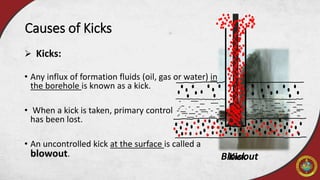
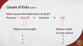
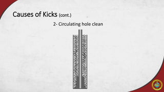
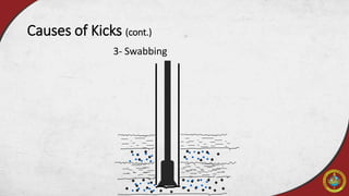
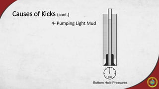
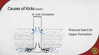
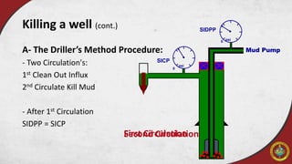
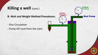
Click to edit Master subtitle style
Well Control
AAPG SU SC
Check every slide as some slides may include nether notes.
Outline
 Introduction
 Causes of Kicks
 Primary, Secondary and Tertiary well control
 Blowout Preventer stack
 Kick Detection Equipment
 killing a well
Outline
 Introduction
 Causes of Kicks
 Primary, Secondary and Tertiary well control
 Blowout Preventer stack
 Kick Detection Equipment
 killing a well
Introduction
Well control is the procedure of maintaining pressure on open
formation (that is exposed to the wellbore) to prevent or direct the
flow of formation fluids into the wellbore.
Or it’s to avoid this situation
• Overbalance
Mud Hydrostatic Pressure > Formation Pressure
• Underbalance
Mud Hydrostatic Pressure < Formation Pressure (Possible Kick!)
Introduction (cont.)
Outline
 Introduction
Causes of Kicks
 Primary, Secondary and Tertiary well control
 Blowout Preventer stack
 Kick Detection Equipment
 killing a well
Blowout
 Kicks:
• Any influx of formation fluids (oil, gas or water) in
the borehole is known as a kick.
• When a kick is taken, primary control
has been lost.
• An uncontrolled kick at the surface is called a
blowout.
Causes of Kicks
Kick
Kicks occur when “underbalance is found”
Underbalance is caused by :
• Increase in Formation Pressure.
• Mud Hydrostatic Reduction.
Causes of Kicks (cont.)
What causes Mud Hydrostatic to drop?
Pressure = Mud Wt X Constant X TVD
Reduce mud weight Reduce length
of mud column
? ?
? ?
? ?
Causes of Kicks (cont.)
1- Running into bubbles
Causes of Kicks (cont.)
2- Circulating hole clean
Causes of Kicks (cont.)
3- Swabbing
Causes of Kicks (cont.)
4- Pumping Light Mud
Causes of Kicks (cont.)
Bottom Hole Pressures
psi
5- Loss of Barite
Causes of Kicks (cont.)
Pit Hole
6- Lost circulation
Causes of Kicks (cont.)
Well Under Control
(Normal Condition)
6- Lost circulation
Causes of Kicks (cont.)
Pressure Exert On
Upper Formation
7- Pull Out of The Hole Dry
Causes of Kicks (cont.)
Rig Floor
Flowline
8- Pull Out of The Hole Wet
Causes of Kicks (cont.)
Rig Floor
Flowline
 Kick Prevention
Causes of Kicks (cont.)
 Monitor trips; in and out.
 Circulate bottoms up if in doubt of hole condition.
 Monitor well at all times.
 Trip carefully in and out.
 Pump out if tight hole.
 Circulate through choke if a lot of gas is expected.
 Keep mud in good shape.
 Always keep hole full.
 Double check effect of lightweight mud/pills.
 Pump good cement.
Outline
 Introduction
 Causes of Kicks
 Primary, Secondary and Tertiary well control
 Blowout Preventer stack
 Kick Detection Equipment
 killing a well
Primary, Secondary and Tertiary well control
You must have an idea of primary, secondary and tertiary well
control and the equipment used to detect the kicks or any
other problem.
Primary Control
Mud Weight
Secondary Control
BOPs
Tertiary Control
Control &Recovery
Primary, Secondary and Tertiary well control (cont.)
The well control system is designed to:
1. Detect a kick
2. Close-in the well at surface
3. Remove the formation fluid which has flowed into the well
4. Make the well safe
1- Primary well control
 Mud Hydrostatic Pressure:
Mud Hydrostatic Pressure > Formation Pressure
2- Secondary well control
 BOP (Blowout Preventer)
 Secondary control is activated only
to restore the primary well control.
3- Tertiary well control:
• Tertiary control involves pumping substances into the wellbore to try
to physically stop the flow down hole.
• This may involve pumping cement with a high risk of having to
abandon the well afterwards.
• However, there is another method that may be employed, called a
Barite Plug …
3-Tertiary well control (cont.)
Barite Plug:
• A barite plug is set by mixing a heavy slurry of barite in water or
diesel oil. It has to be kept moving while mixing and pumping.
• Once the slurry is in position down hole and pumping stops, the
barite rapidly settles out to form an impermeable mass that will
hopefully stop the flow of formation fluid.
Outline
 Introduction
 Causes of Kicks
Primary, Secondary and Tertiary well control
 Blowout Preventer stack
 Kick Detection Equipment
 killing a well
Blowout Preventer stack
The primary function of the BOP is to form
a rapid and reliable seal around the drill
string or across the empty hole, so as to
control down hole pressures.
Note: it is installed after the surface casing,
before this a diverter is installed.
Blowout Preventer stack (cont.)
There are two types of preventers:
1. Bag-type preventer (or annular preventer):
• Contains a large rubber seal, which is circular if
viewed from above and conical if viewed from the
side. This is held inside a steel chamber.
• Below the rubber element is a hydraulically operated
piston with a matching conical shape on top to fit the
rubber underside.
Blowout Preventer stack (cont.)
2. Ram-type preventer:
• The other type of preventer uses a pair of large steel rams that shut under
high hydraulic pressure, with great force.
• These rams are interchangeable and are of different types:
Fixed pipe ram
Variable bore pipe ram
Blind rams
Shear rams
Blind-Shear rams
Casing shear rams
• Normally, a BOP stack would have at least one bag preventer and two
ram preventers.
• Stacks for deeper wells might have up to four ram preventers and two
annular preventers.
• The ram preventers generally have a higher pressure rating and are
always installed below the bag preventers.
• If only two ram preventers are used, the bottom set will normally be
blind-shear rams, and the upper set will be pipe rams.
• One reason for placing the blind rams on the bottom is that if the
pipe rams or annular leaks, it is possible to close the blind rams below
and fix the leak above.
Blowout Preventer stack (cont.)
 Choke Valves:
Below the rams are pipes that come out to the side. These
are called side outlets and are used to allow flow out of or
into the annulus during well killing operations.
Blowout Preventer stack (cont.)
 BOP Control System:
also known as the Accumulator or
the Koomey Unit
Energy stored in this unit to operate
the BOP
A reserve hydraulic fluid tank
A set of cylinders holding fluid under
high pressure
Two manifolds
Blowout Preventer stack (cont.)
 BOP Control System:
Two pressure regulator that feeds fluid
 From high pressure to low
 From low pressure to high
A set of valves
A valve
 controls the opening and closing of the bag preventer
Two sets of pumps to maintain system pressure
Blowout Preventer stack (cont.)
 Subsea BOP systems:
• attached to the top of the surface casing
at the seabed.
• contains extra control systems when
compared to a surface BOP.
Blowout Preventer stack (cont.)
Outline
 Introduction
 Causes of Kicks
 Primary, Secondary and Tertiary well control
 Blowout Preventer stack
 Kick Detection Equipment
 killing a well
Kick Detection Equipment
There are two main kick detection systems that give a direct indication
of a kick:
1. Pit volume totalizer
2. Flow indicator
Kick Detection Equipment (cont.)
 The pit volume totalizer PVT:
• It provides a readout showing the
total volume of drilling fluid held on
the surface.
• If this total increases, and the
increase is not due to the mud
engineer adding chemicals or fresh
mud to the system, a kick is
occurring.
 The flow indicator:
• This system consists of an instrument
attached to a paddle that sits in the flow
line from the annulus. This paddle is
pushed up by the returning mud stream. If
the flow rate increases, an alarm will
sound.
• However, the paddle-type flow indicator is
prone to false alarms because of cuttings
and other debris that may stick to the
paddle or build up underneath it.
Kick Detection Equipment (cont.)
 Kick Warning Signs
1.ROP changes
• Less overbalance
• Softer rock
2.Hole condition
• Squeezing rock
• Torque / Drag / Fill
3.Data from Mud
• Gas
• Cuttings
• Temperature
Kick Warning Signs & Indicators
• Chlorides
• Shale Property
• Trip Monitor
Nocked
or packed off cutting
Drilled cuttings
Major Warning Signs:
• Improper fill up or displacement during trips
• Connection gas
• Increased background gas
• Increased drilling rate ( known as Drilling Break or Fast Break)
• Flowline mud temperature increase
• Increased chloride content of mud
• Increased drill string torque
• Increased drill string drag
• Increased number and size of cuttings
• Decreasing shale density
Kick Warning Signs & Indicators (cont.)
 Surface Kick Indicators
• Excess flow from the well when tripping
• Return flow rate increase when pumping
• Pit gain
• Flow from well with pumps off
Kick Warning Signs & Indicators (cont.)
Outline
 Introduction
 Causes of Kicks
 Primary, Secondary and Tertiary well control
 Blowout Preventer stack
 Kick Detection Equipment
killing a well
Killing a well
First, how to shut-in the well:
 Reason for Shut In:
1- To prevent blowout.
2- To allow pressure reading to be taken for
kill mud
 Shut In Methods
1. Hard (Drilling / Trapping)
2. Soft (Drilling / Trapping)
Hard Vs.
- Quicker
- Less to Remember
- Smaller Influx
Soft
- Slower & Reduces Water Hammer Effect
- Checks if choke line is Clean
- Larger Influx
Killing a well (cont.)
Simplifying the Initial Phase of Killing the well
Driller’s Method Wait and Weight
Volumetric Bullheading
A- The Driller’s Method:
 The Driller`s method is one of the oldest well killing methods and it was
developed for shallow vertical wells.
 As time moved on, wells got deeper and went from vertical into more
inclined pathways.
 The method got further developed to overcome the new challenges
related to deviated well paths.
Killing a well (cont.)
A- The Driller’s Method Procedure:
 Removing Kick:
1. Kick detection
2. Stop mud pumps and rotation of the drill string rotation
3. Close the BOP
4. Monitor the shut-in pressure until it levels out – the wellbore
pressure is equal to formation pressure
5. Then open choke line and circulate the kick out through the choke
line to the separator/flare
Killing a well (cont.)
A- The Driller’s Method Procedure:
Another option is to reverse kill or bullhead, this is done by forcing the
kick back into the formation again.
Killing a well (cont.)
SIDPP
SICP
0
psi
psi
0
Mud PumpA- The Driller’s Method Procedure:
- Two Circulation's:
1st Clean Out Influx
2nd Circulate Kill Mud
- After 1st Circulation
SIDPP = SICP
Killing a well (cont.)
First CirculationSecond Circulation
B- Wait and Weight Method
•The Wait and Weight method kills the kick faster and keeps wellbore
and surface pressures lower than any other method.
•Requires good mixing facilities, full crews, and more supervision than
most other methods.
•Fluid weight is increased before circulation begins, hence the name
Wait and Weight.
Killing a well (cont.)
B- Wait and Weight Method Procedures:
1. Shut-in well after kick.
2. Record kick size and stabilize SIDPP and SICP, calculate kill fluid
density.
3. Pits are weighted up as other calculations are performed.
4. Once pits are weighted, start circulating kill weight fluid by
gradually bringing up the pump up to the kill rate while using the
choke to maintain constant casing pressure at the shut-in value.
 Remember to hold pump rate constant.
Killing a well (cont.)
B- Wait and Weight Method Procedures:
5. Follow pressure chart/graph as kill fluid is pumped down the string
to bit.
6. Once kill fluid is at the bit/end of string, FCP should be realized.
7. Maintain constant FCP circulating pressure until the kill fluid
completely fills the well.
8. Shut down pump and check for flow, Close choke and check
pressures.
9. If no pressure is noted, open choke , open BOP.
Killing a well (cont.)
0 psi
0
Mud Pump
psiCasing
Pressure
Drillpipe
Pressure
B- Wait and Weight Method Procedures:
- One Circulation
- Pump kill mud from the start
Killing a well (cont.)
C- Volumetric Method :
• The volumetric method is a way of allowing controlled expansion of
gas during migration.
• The Volumetric method is based on the assumption that the influx is
gas that migrates upwards in the well. It cannot be used if the influx
fluid is either salt water or oil.
Killing a well (cont.)
C- Volumetric Method:
• The reasons for using this method instead of another kill method are based
on different variables in the well. Some of them are listed below:
1. If there are no drill string in the well
2. If the drill bit or the drill string has been plugged with some kind of
debris
3. Hole collapse can be a reason – this prevents circulation
4. If there has been a power failure and mud pumps along with
emergency pumps are down
5. If there is a long way between drill string and bottom of the well
6. Not able to circulate due to drill string has been cut and dropped
into the well
Killing a well (cont.)
C- Volumetric Method Procedures:
• In this method the choke is opened and closed in steps to bleed of the
inflow gas. It is performed by staying within the designated pore and
fracture pressures together with a safety margin.
• As gas moves up and pressure in the well increases, the choke is opened to
bleed off and reduce the well pressure and it is then closed when the
pressure drops to a certain level.
• This procedure is maintained until the gas is completely out of the well.
Killing a well (cont.)
D- Bullheading Method Procedures:
• Operators sometimes have to look at different alternatives to solve
critical well control problems. When conventional method of
circulating down the drill string and up the annulus no longer is an
option, an alternative is to use a technique called bullheading.
• This method is performed with the use of pumps in a closed in well,
the influx fluids are then pushed- and forced back down into the
weakest point of the exposed open hole interval.
Killing a well (cont.)
D- Bullheading Method Procedures:
• Bullheading is done by adding some pressure, in this way the wellbore
pressure gets overbalanced compared to the reservoir pressure and the
formation fluids are pushed back into the formation. The pressure
acting on the bottom during a bullheading operation is
PBH = Pres + Pover
PBH = Bottom hole pressure Pres = Reservoir pressure
Pover = Overpressure
Killing a well (cont.)
D- Bullheading Method Procedures:
• The over pressure is dependent to the reservoir properties
(permeability and porosity) and the influx concentration.
• The higher the properties in the reservoir are (high permeability and
porosity) the lower the overbalance pressure needs to be in order to
force the influx back into the formation.
Killing a well (cont.)
Well Control

Well Control

  • 1.
    Click to editMaster subtitle style Well Control AAPG SU SC Check every slide as some slides may include nether notes.
  • 2.
    Outline  Introduction  Causesof Kicks  Primary, Secondary and Tertiary well control  Blowout Preventer stack  Kick Detection Equipment  killing a well
  • 3.
    Outline  Introduction  Causesof Kicks  Primary, Secondary and Tertiary well control  Blowout Preventer stack  Kick Detection Equipment  killing a well
  • 4.
    Introduction Well control isthe procedure of maintaining pressure on open formation (that is exposed to the wellbore) to prevent or direct the flow of formation fluids into the wellbore. Or it’s to avoid this situation
  • 5.
    • Overbalance Mud HydrostaticPressure > Formation Pressure • Underbalance Mud Hydrostatic Pressure < Formation Pressure (Possible Kick!) Introduction (cont.)
  • 6.
    Outline  Introduction Causes ofKicks  Primary, Secondary and Tertiary well control  Blowout Preventer stack  Kick Detection Equipment  killing a well
  • 7.
    Blowout  Kicks: • Anyinflux of formation fluids (oil, gas or water) in the borehole is known as a kick. • When a kick is taken, primary control has been lost. • An uncontrolled kick at the surface is called a blowout. Causes of Kicks Kick
  • 8.
    Kicks occur when“underbalance is found” Underbalance is caused by : • Increase in Formation Pressure. • Mud Hydrostatic Reduction. Causes of Kicks (cont.)
  • 9.
    What causes MudHydrostatic to drop? Pressure = Mud Wt X Constant X TVD Reduce mud weight Reduce length of mud column ? ? ? ? ? ? Causes of Kicks (cont.)
  • 10.
    1- Running intobubbles Causes of Kicks (cont.)
  • 11.
    2- Circulating holeclean Causes of Kicks (cont.)
  • 12.
    3- Swabbing Causes ofKicks (cont.)
  • 13.
    4- Pumping LightMud Causes of Kicks (cont.) Bottom Hole Pressures psi
  • 14.
    5- Loss ofBarite Causes of Kicks (cont.) Pit Hole
  • 15.
    6- Lost circulation Causesof Kicks (cont.) Well Under Control (Normal Condition)
  • 16.
    6- Lost circulation Causesof Kicks (cont.) Pressure Exert On Upper Formation
  • 17.
    7- Pull Outof The Hole Dry Causes of Kicks (cont.) Rig Floor Flowline
  • 18.
    8- Pull Outof The Hole Wet Causes of Kicks (cont.) Rig Floor Flowline
  • 19.
     Kick Prevention Causesof Kicks (cont.)  Monitor trips; in and out.  Circulate bottoms up if in doubt of hole condition.  Monitor well at all times.  Trip carefully in and out.  Pump out if tight hole.  Circulate through choke if a lot of gas is expected.  Keep mud in good shape.  Always keep hole full.  Double check effect of lightweight mud/pills.  Pump good cement.
  • 20.
    Outline  Introduction  Causesof Kicks  Primary, Secondary and Tertiary well control  Blowout Preventer stack  Kick Detection Equipment  killing a well
  • 21.
    Primary, Secondary andTertiary well control You must have an idea of primary, secondary and tertiary well control and the equipment used to detect the kicks or any other problem. Primary Control Mud Weight Secondary Control BOPs Tertiary Control Control &Recovery
  • 22.
    Primary, Secondary andTertiary well control (cont.) The well control system is designed to: 1. Detect a kick 2. Close-in the well at surface 3. Remove the formation fluid which has flowed into the well 4. Make the well safe
  • 23.
    1- Primary wellcontrol  Mud Hydrostatic Pressure: Mud Hydrostatic Pressure > Formation Pressure
  • 24.
    2- Secondary wellcontrol  BOP (Blowout Preventer)  Secondary control is activated only to restore the primary well control.
  • 25.
    3- Tertiary wellcontrol: • Tertiary control involves pumping substances into the wellbore to try to physically stop the flow down hole. • This may involve pumping cement with a high risk of having to abandon the well afterwards. • However, there is another method that may be employed, called a Barite Plug …
  • 26.
    3-Tertiary well control(cont.) Barite Plug: • A barite plug is set by mixing a heavy slurry of barite in water or diesel oil. It has to be kept moving while mixing and pumping. • Once the slurry is in position down hole and pumping stops, the barite rapidly settles out to form an impermeable mass that will hopefully stop the flow of formation fluid.
  • 27.
    Outline  Introduction  Causesof Kicks Primary, Secondary and Tertiary well control  Blowout Preventer stack  Kick Detection Equipment  killing a well
  • 28.
    Blowout Preventer stack Theprimary function of the BOP is to form a rapid and reliable seal around the drill string or across the empty hole, so as to control down hole pressures. Note: it is installed after the surface casing, before this a diverter is installed.
  • 29.
    Blowout Preventer stack(cont.) There are two types of preventers: 1. Bag-type preventer (or annular preventer): • Contains a large rubber seal, which is circular if viewed from above and conical if viewed from the side. This is held inside a steel chamber. • Below the rubber element is a hydraulically operated piston with a matching conical shape on top to fit the rubber underside.
  • 30.
    Blowout Preventer stack(cont.) 2. Ram-type preventer: • The other type of preventer uses a pair of large steel rams that shut under high hydraulic pressure, with great force. • These rams are interchangeable and are of different types: Fixed pipe ram Variable bore pipe ram Blind rams Shear rams Blind-Shear rams Casing shear rams
  • 31.
    • Normally, aBOP stack would have at least one bag preventer and two ram preventers. • Stacks for deeper wells might have up to four ram preventers and two annular preventers. • The ram preventers generally have a higher pressure rating and are always installed below the bag preventers. • If only two ram preventers are used, the bottom set will normally be blind-shear rams, and the upper set will be pipe rams. • One reason for placing the blind rams on the bottom is that if the pipe rams or annular leaks, it is possible to close the blind rams below and fix the leak above. Blowout Preventer stack (cont.)
  • 32.
     Choke Valves: Belowthe rams are pipes that come out to the side. These are called side outlets and are used to allow flow out of or into the annulus during well killing operations. Blowout Preventer stack (cont.)
  • 33.
     BOP ControlSystem: also known as the Accumulator or the Koomey Unit Energy stored in this unit to operate the BOP A reserve hydraulic fluid tank A set of cylinders holding fluid under high pressure Two manifolds Blowout Preventer stack (cont.)
  • 34.
     BOP ControlSystem: Two pressure regulator that feeds fluid  From high pressure to low  From low pressure to high A set of valves A valve  controls the opening and closing of the bag preventer Two sets of pumps to maintain system pressure Blowout Preventer stack (cont.)
  • 35.
     Subsea BOPsystems: • attached to the top of the surface casing at the seabed. • contains extra control systems when compared to a surface BOP. Blowout Preventer stack (cont.)
  • 36.
    Outline  Introduction  Causesof Kicks  Primary, Secondary and Tertiary well control  Blowout Preventer stack  Kick Detection Equipment  killing a well
  • 37.
    Kick Detection Equipment Thereare two main kick detection systems that give a direct indication of a kick: 1. Pit volume totalizer 2. Flow indicator
  • 38.
    Kick Detection Equipment(cont.)  The pit volume totalizer PVT: • It provides a readout showing the total volume of drilling fluid held on the surface. • If this total increases, and the increase is not due to the mud engineer adding chemicals or fresh mud to the system, a kick is occurring.
  • 39.
     The flowindicator: • This system consists of an instrument attached to a paddle that sits in the flow line from the annulus. This paddle is pushed up by the returning mud stream. If the flow rate increases, an alarm will sound. • However, the paddle-type flow indicator is prone to false alarms because of cuttings and other debris that may stick to the paddle or build up underneath it. Kick Detection Equipment (cont.)
  • 40.
     Kick WarningSigns 1.ROP changes • Less overbalance • Softer rock 2.Hole condition • Squeezing rock • Torque / Drag / Fill 3.Data from Mud • Gas • Cuttings • Temperature Kick Warning Signs & Indicators • Chlorides • Shale Property • Trip Monitor Nocked or packed off cutting Drilled cuttings
  • 41.
    Major Warning Signs: •Improper fill up or displacement during trips • Connection gas • Increased background gas • Increased drilling rate ( known as Drilling Break or Fast Break) • Flowline mud temperature increase • Increased chloride content of mud • Increased drill string torque • Increased drill string drag • Increased number and size of cuttings • Decreasing shale density Kick Warning Signs & Indicators (cont.)
  • 42.
     Surface KickIndicators • Excess flow from the well when tripping • Return flow rate increase when pumping • Pit gain • Flow from well with pumps off Kick Warning Signs & Indicators (cont.)
  • 43.
    Outline  Introduction  Causesof Kicks  Primary, Secondary and Tertiary well control  Blowout Preventer stack  Kick Detection Equipment killing a well
  • 44.
    Killing a well First,how to shut-in the well:  Reason for Shut In: 1- To prevent blowout. 2- To allow pressure reading to be taken for kill mud  Shut In Methods 1. Hard (Drilling / Trapping) 2. Soft (Drilling / Trapping) Hard Vs. - Quicker - Less to Remember - Smaller Influx Soft - Slower & Reduces Water Hammer Effect - Checks if choke line is Clean - Larger Influx
  • 45.
    Killing a well(cont.) Simplifying the Initial Phase of Killing the well Driller’s Method Wait and Weight Volumetric Bullheading
  • 46.
    A- The Driller’sMethod:  The Driller`s method is one of the oldest well killing methods and it was developed for shallow vertical wells.  As time moved on, wells got deeper and went from vertical into more inclined pathways.  The method got further developed to overcome the new challenges related to deviated well paths. Killing a well (cont.)
  • 47.
    A- The Driller’sMethod Procedure:  Removing Kick: 1. Kick detection 2. Stop mud pumps and rotation of the drill string rotation 3. Close the BOP 4. Monitor the shut-in pressure until it levels out – the wellbore pressure is equal to formation pressure 5. Then open choke line and circulate the kick out through the choke line to the separator/flare Killing a well (cont.)
  • 48.
    A- The Driller’sMethod Procedure: Another option is to reverse kill or bullhead, this is done by forcing the kick back into the formation again. Killing a well (cont.)
  • 49.
    SIDPP SICP 0 psi psi 0 Mud PumpA- TheDriller’s Method Procedure: - Two Circulation's: 1st Clean Out Influx 2nd Circulate Kill Mud - After 1st Circulation SIDPP = SICP Killing a well (cont.) First CirculationSecond Circulation
  • 50.
    B- Wait andWeight Method •The Wait and Weight method kills the kick faster and keeps wellbore and surface pressures lower than any other method. •Requires good mixing facilities, full crews, and more supervision than most other methods. •Fluid weight is increased before circulation begins, hence the name Wait and Weight. Killing a well (cont.)
  • 51.
    B- Wait andWeight Method Procedures: 1. Shut-in well after kick. 2. Record kick size and stabilize SIDPP and SICP, calculate kill fluid density. 3. Pits are weighted up as other calculations are performed. 4. Once pits are weighted, start circulating kill weight fluid by gradually bringing up the pump up to the kill rate while using the choke to maintain constant casing pressure at the shut-in value.  Remember to hold pump rate constant. Killing a well (cont.)
  • 52.
    B- Wait andWeight Method Procedures: 5. Follow pressure chart/graph as kill fluid is pumped down the string to bit. 6. Once kill fluid is at the bit/end of string, FCP should be realized. 7. Maintain constant FCP circulating pressure until the kill fluid completely fills the well. 8. Shut down pump and check for flow, Close choke and check pressures. 9. If no pressure is noted, open choke , open BOP. Killing a well (cont.)
  • 53.
    0 psi 0 Mud Pump psiCasing Pressure Drillpipe Pressure B-Wait and Weight Method Procedures: - One Circulation - Pump kill mud from the start Killing a well (cont.)
  • 54.
    C- Volumetric Method: • The volumetric method is a way of allowing controlled expansion of gas during migration. • The Volumetric method is based on the assumption that the influx is gas that migrates upwards in the well. It cannot be used if the influx fluid is either salt water or oil. Killing a well (cont.)
  • 55.
    C- Volumetric Method: •The reasons for using this method instead of another kill method are based on different variables in the well. Some of them are listed below: 1. If there are no drill string in the well 2. If the drill bit or the drill string has been plugged with some kind of debris 3. Hole collapse can be a reason – this prevents circulation 4. If there has been a power failure and mud pumps along with emergency pumps are down 5. If there is a long way between drill string and bottom of the well 6. Not able to circulate due to drill string has been cut and dropped into the well Killing a well (cont.)
  • 56.
    C- Volumetric MethodProcedures: • In this method the choke is opened and closed in steps to bleed of the inflow gas. It is performed by staying within the designated pore and fracture pressures together with a safety margin. • As gas moves up and pressure in the well increases, the choke is opened to bleed off and reduce the well pressure and it is then closed when the pressure drops to a certain level. • This procedure is maintained until the gas is completely out of the well. Killing a well (cont.)
  • 57.
    D- Bullheading MethodProcedures: • Operators sometimes have to look at different alternatives to solve critical well control problems. When conventional method of circulating down the drill string and up the annulus no longer is an option, an alternative is to use a technique called bullheading. • This method is performed with the use of pumps in a closed in well, the influx fluids are then pushed- and forced back down into the weakest point of the exposed open hole interval. Killing a well (cont.)
  • 58.
    D- Bullheading MethodProcedures: • Bullheading is done by adding some pressure, in this way the wellbore pressure gets overbalanced compared to the reservoir pressure and the formation fluids are pushed back into the formation. The pressure acting on the bottom during a bullheading operation is PBH = Pres + Pover PBH = Bottom hole pressure Pres = Reservoir pressure Pover = Overpressure Killing a well (cont.)
  • 59.
    D- Bullheading MethodProcedures: • The over pressure is dependent to the reservoir properties (permeability and porosity) and the influx concentration. • The higher the properties in the reservoir are (high permeability and porosity) the lower the overbalance pressure needs to be in order to force the influx back into the formation. Killing a well (cont.)

Editor's Notes

  • #5 Harms of loss well control • Personal injury and/or loss of life • Large economic & financial loss • Resource waste • Damage and/or loss of equipment • Environment pollution • Negative governmental reaction • Interrupt production plan
  • #6 Formation Pressure - All formations we drilled consists of rock  grains and pore space. - Formation fluid pressure is the pressure of  the fluids that exist in pore space Mud hydrostatic pressure - The pressure exerted by the mud column in a borehole at certain depth Well control is to keep it always overbalanced conditions. Kick!!
  • #8 When the drill bit enters a permeable formation the pressure in the pore space of the formation may be greater than the hydrostatic pressure exerted by the mud column. If this is so, formation fluids will enter the wellbore and start displacing mud from the hole. Any influx of formation fluids (oil, gas or water) in the borehole is known as a kick.
  • #9 We can not control abnormal formation pressure as its causes are: Under Compaction Salt Dome Artesian Effect But mud hydrostatic pressure is controlable…
  • #10 Note that TVD in this equation is true vertical length of mud column not the whole well bore
  • #11 When running into bubbles will displace mud which results into
  • #12 This will remove cuttings with chemical solids within the mud causing the mud weight to be reduced
  • #13 Swabbing: - Momentary reduction in BHP due to reduction in hydrostatic force cased by the upward suction action of the drill string, which can allow a small invasion into well bore. Main Causes: - Pulling pipe too fast - High viscosity mud - Small collar to hole wall clearance - Balled-up bit
  • #15 Loss of Barite because of: Centrifuge pump when cleaning the mud Sahleshakers Desilters Poor Mud/Settling
  • #18 Pressure or Level Drop Per Foot Pulled for Dry Pipe = (Mud Grad X Metal Displacement) / ( Casing Cap - Metal Displacement)
  • #19 Pressure or Level Drop Per Foot Pulled for Wet Pipe = (Mud Grad X Metal Disp. + pipe Cap) / [Casing Cap - (Metal Disp. + Pipe Cap)] Much higher than dry pipe.. Why!
  • #23 Failure to do this results in the uncontrolled flow fluids -known as a blowout- which may cause loss of lives and equipment, damage to the environment and the loss of oil or gas reserves.
  • #24 As shown in the this figure, mud hydrostatic pressure must be attained greater than the formation pressure through the whole drilling section. We occasionally need to use a different type of mud with higher pressure gradient ( mud weight ) in abnormal pressure formations to avoid kick or blowout.
  • #25  If primary control is lost and formation fluids start to flow into the well, secondary well control is initiated by closing the blowout preventer (BOP) to seal off the annulus. This stops mud leaving the well at the surface. The aim of secondary control is to prevent the fluids flowing into the wellbore from getting to the surface and eventually allow the influx to be circulated to surface and safely discharged, while preventing further influx down hole. Now we can restore the primary well control.
  • #26 It sometimes happens that the blowout preventer equipment fails or the hole starts to allow fluid to leak away into an underground formation. Secondary control cannot be maintained, and formation fluid again starts to enter the wellbore. This is now a dangerous situation. If control is not restored, there may be a blowout. Tertiary control has to be applied to try to stop the flow.
  • #29 Diverter: Used to divert the flow from the well, it doesn’t hold pressure. Usually used in shallow holes. Integrated with vent line – Drilling spool
  • #31 Fixed pipe ram: The seal is sized to fit one outside diameter only. Variable bore pipe ram: The seal element can accommodate a narrow range of diameters, for example 3½" to 7 in". It can only seal on round pipe, not square or hexagonal shapes. Blind rams: (with no pipe in hole) are designed to seal (with pipes in hole) are designed to squeeze the pipe but without sealing Shear rams: are designed to shear the pipe in the well and seal the wellbore Blind-Shear rams: also known as shear seal rams or sealing shear rams; have blades incorporated that can cut through pipe and seal the wellbore. Casing shear rams: These are heavy-duty shear rams that do not seal but can cut through heavy pipe, such as casing. These are found in subsea BOP stacks.
  • #33 A choke valve allows fluid to flow through it, but it has a variable sized opening. This allows mud to flow out of the annulus but at the same time keeps pressure on the annulus. The pointed part of the needle moves in and out in respect to the choke bean. As the needle moves in, the gap closes. For a particular flow rate through the choke, this will increase the pressure upstream of the choke. It would be possible to use a normal valve as a choke. However, mud that contains solids (barite, bentonite, sand, or other drilled particles) is quite abrasive when flowing through a restriction at high pressure. A normal valve would soon erode and fail to hold pressure if it were used to exert pressure on the flowing mud. A choke valve is designed to handle this operation with minimum erosion, by its design and by the use of tungsten carbide internal components.
  • #34 BOP units (bag and ram preventers and some valves) are moved using hydraulic fluid under pressure to provide this pressure, a hydraulic control system is used that contains several elements: A reserve hydraulic fluid tank holding fluid at atmospheric pressure. A set of cylinders holding fluid under high pressure (usually 3,000 psi) with pressurized nitrogen. Nitrogen is used because it can keep its gaseous state for very high pressures and low temperature. A high-pressure manifold connected to the cylinders. A low-pressure manifold that contains fluid at the working pressure of the ram preventers (usually 1,500 psi).
  • #35 A pressure regulator that feeds fluid from the high-pressure manifold to the low-pressure manifold and that reduces the pressure to the working pressure. A set of valves attached to the low-pressure manifold that can direct working pressure fluid to the rams (to open or to close them) and that directs exhaust fluid back to the reserve hydraulic fluid tank. A valve that controls the opening and closing of the bag preventer. A pressure regulator that feeds fluid from the low-pressure manifold to the bag preventer control valve. Two sets of pumps to maintain system pressure. One set is driven by compressed air from the rig air system, the other is powered by electricity.
  • #36 The hydraulic fluid in this case is water mixed with a nontoxic soluble oil so that pollution is avoided.
  • #39 It can display the volume in any particular tank and can also add up all of the surface active volumes so that any change in the total surface volume may be detected. The PVT also includes alarms that can be set so that changes beyond a set amount lost or gained will fire the alarm.
  • #40 If the flow rate out increases but the mud pump speed has not been increased, it is possible that the extra flow out is due to an influx entering the wellbore. Generally the flow indicator will give the first positive indication of a kick, followed by an increase in the active volume.
  • #41 Warning Signs: Information from the well that tells you that the well may be getting close to being “Underbalanced”. Your safety margin is getting less. Kick warning signs came from three channels: Drilling rate. Hole condition. Data from mud.
  • #42 Factors affecting ROP: WOB RPM Bit type Hydraulics Rock type Overbalance
  • #43 What action to take? First : shut the well in Second : choose and use a kill method to restore the mud hydrostatic pressure to level that re-establishes primary control
  • #45 Soft/Drilling: Line up with Remote Choke opened. Raise kelly/top drive until tool joint is above rotary table Shut down mud pumps Open choke line valve (HCR) at stack Check that adjustable choke is open Close annular preventer [API Soft Shut in States BOP (It Does Not Specify an Annular) ] Close adjustable choke Record shut in pressure and pit gain ________________________________________________________________________________________________________ Soft/Tripping: Line up With Remote Choke Opened. Install and make up the fully opened SAFETY VALVE in the drill string. Close the safety valve Open choke line valve (HCR) at stack Check that adjustable choke is open Close annular preventer [API soft shut in states bop (it does not specify an annular) ] Close adjustable choke Pick up and make up kelly/Top drive Open safety valve Record shut in pressures and pit gain ________________________________________________________________________________________________________ Hard/Drilling: Line up With Remote Choke Closed. Raise kelly/top drive until tool joint is above rotary table Shut down mud pumps Close ram preventer [API soft shut in states BOP (it does not specify a ram) ] open choke line valve (HCR) at stack Record shut in pressure and pit gain ________________________________________________________________________________________________________ Hard/Tripping: Line up With Remote Choke Closed. Install and make up the fully opened SAFETY VALVE in the drill string. Close the safety valve Close ram preventer [API soft shut in states BOP (it does not specify a ram)] Open choke line valve (HCR) at stack Pick up and make up kelly?Top drive Open safety valve Record shut in pressures and pit gain
  • #47 More time to kill the well is needed in this method than other methods. It may cause slightly higher pressure in the annulus than other methods.
  • #50 SICP: Shut-In Casing Pressure SIDPP: Shut-In Drill Pipe Pressure 1st Circulation: Start up - bring pumps up to kill rate holding casing pressure constant When up to speed look at drill pipe pressure. Hold it constant at this value for complete circulation On completion of circulation shut down the reverse of start up procedure If annulus is clean S.I.C.P will now read S.I.D.P.P If annulus is not clean then S.I.C.P will be greater than S.I.D.P.P 2nd circulation: Start up - bring pumps up to kill rate holding casing pressure constant When up to speed maintain casing pressure constant until kill mud is at the bit With kill mud at bit switch to drill pipe pressure and hold constant until clean mud returns at surface It may be preferred to use the wait and weight procedure for the 2nd circulation. This is in case of any influx that was not cleaned out in the1st circulation
  • #54 - Procedure: Start up - bring pumps up to kill rate holding casing pressure constant Once up to speed the drill pipe pressure should equal I.C.P (initial casing pressure) Allow drill pipe pressure to fall from IC.P to F.C.P as kill mud is pumped to the bit with kill mud at the bit hold drill pipe pressure constant at F.C.P until kill mud returns at surface - Comparison: Ease of Calculation ( Driller Method ) Lower Annulus Pressure ( Wait & Weight) Shortest Circulating Time (Wait & Weight )
  • #55 Compared to Driller`s method and W&W method the Volumetric method is used in situations where there are no possibility to circulate out the kick conventionally
  • #58 Bullheading method may also be the safest option if personnel do not hold the right knowledge to calculate the pressures and volumes required to perform conventional kill circulation process . It is also the only option if the H2S content is too high to be handled on surface, another if the kick is too large with respect to separator capacities or there is a potential risk of breaking the casing shoe.