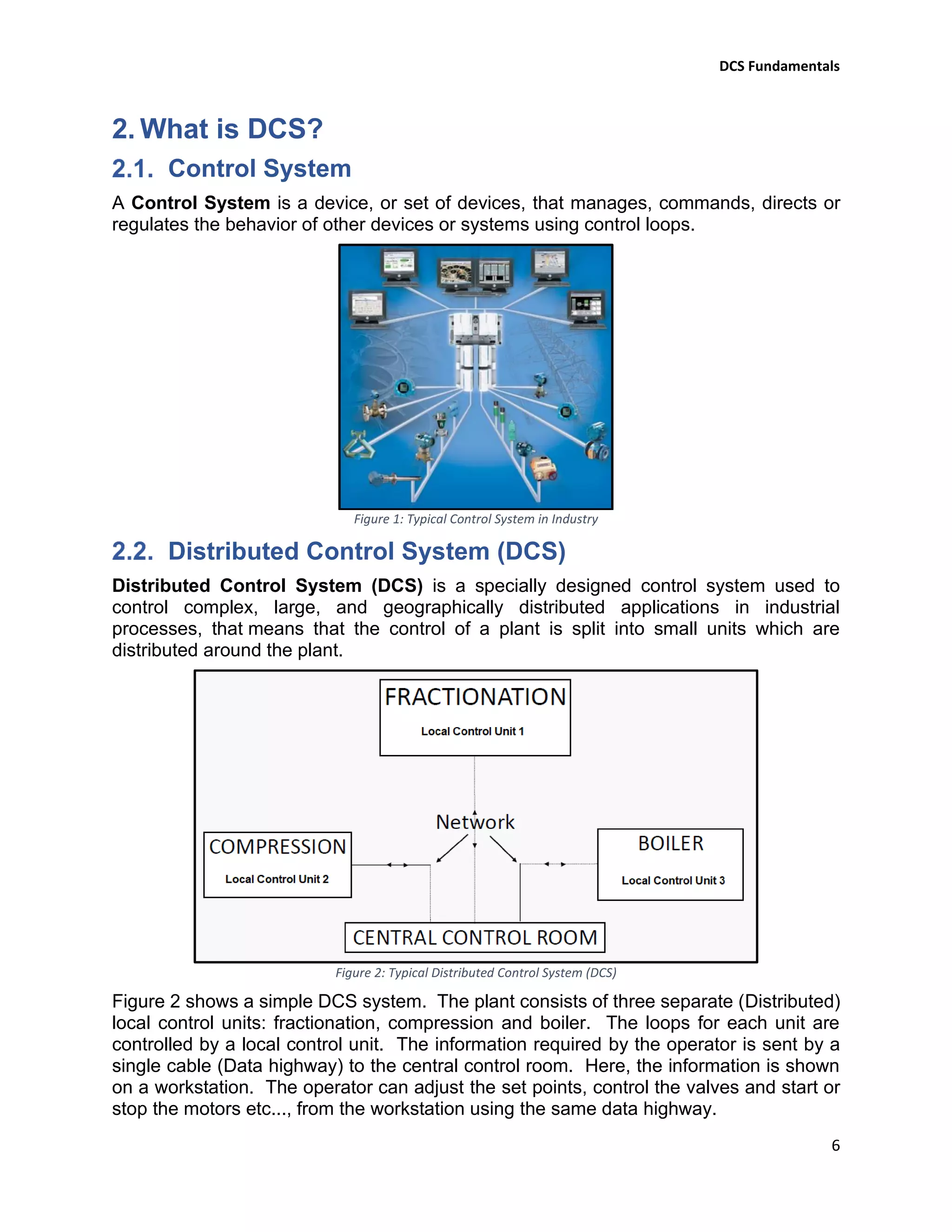
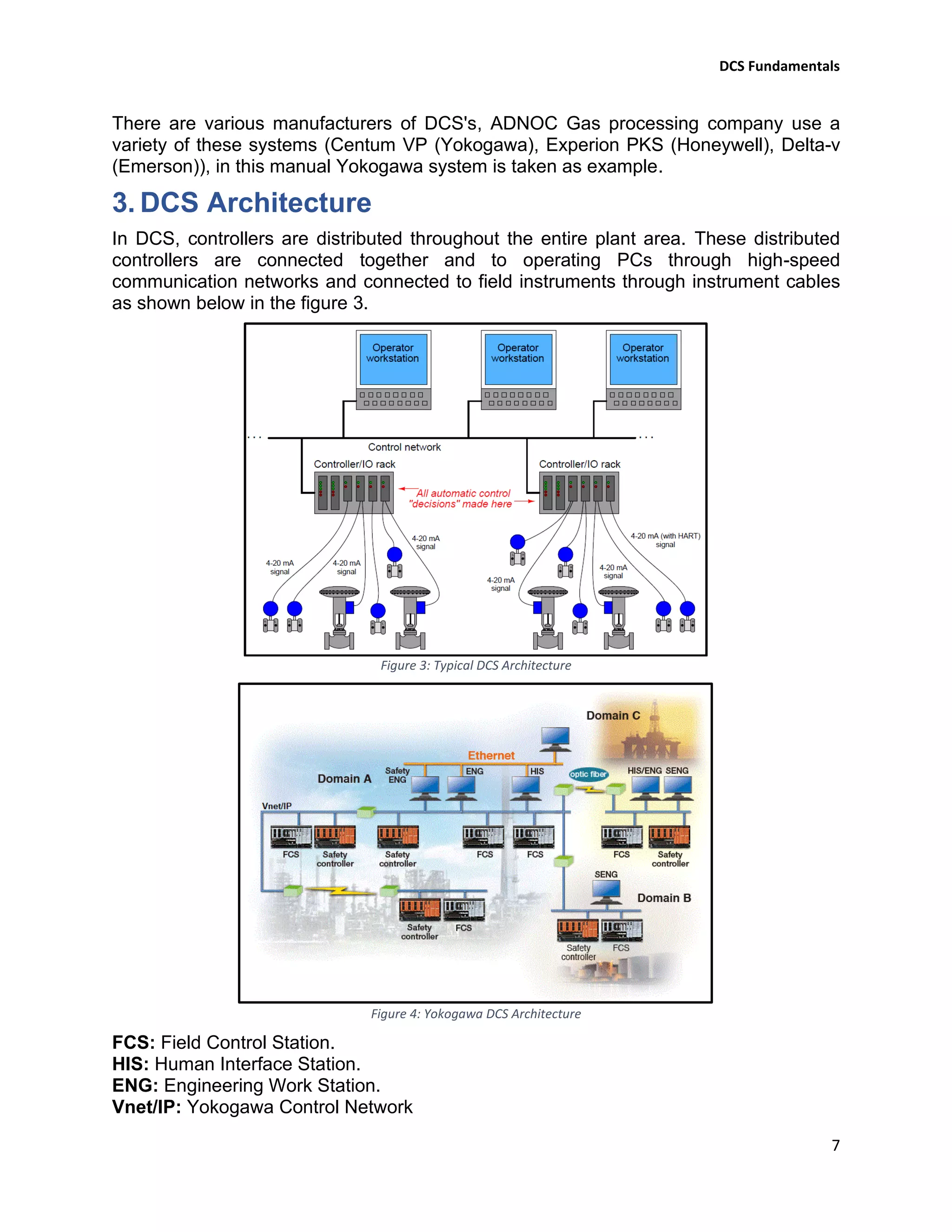
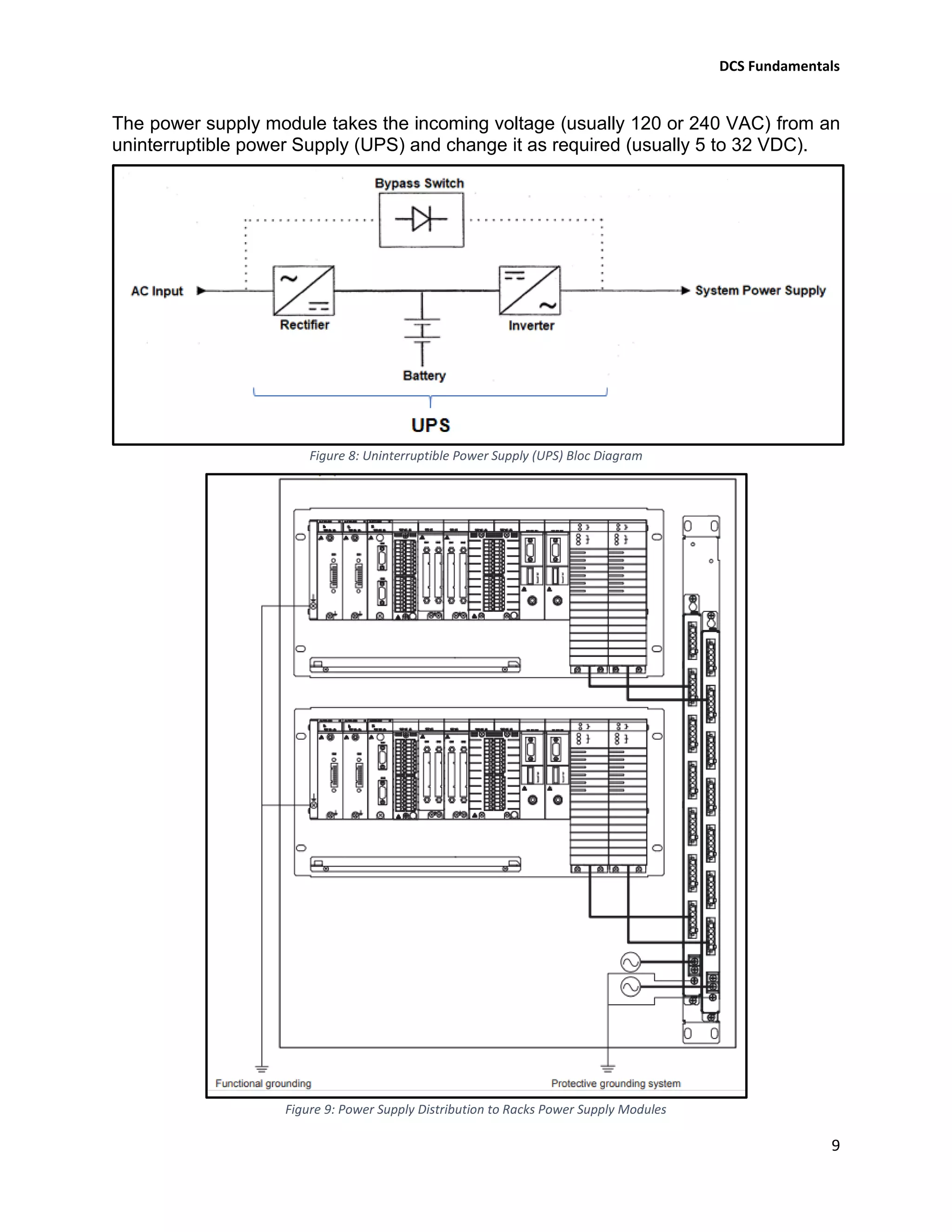
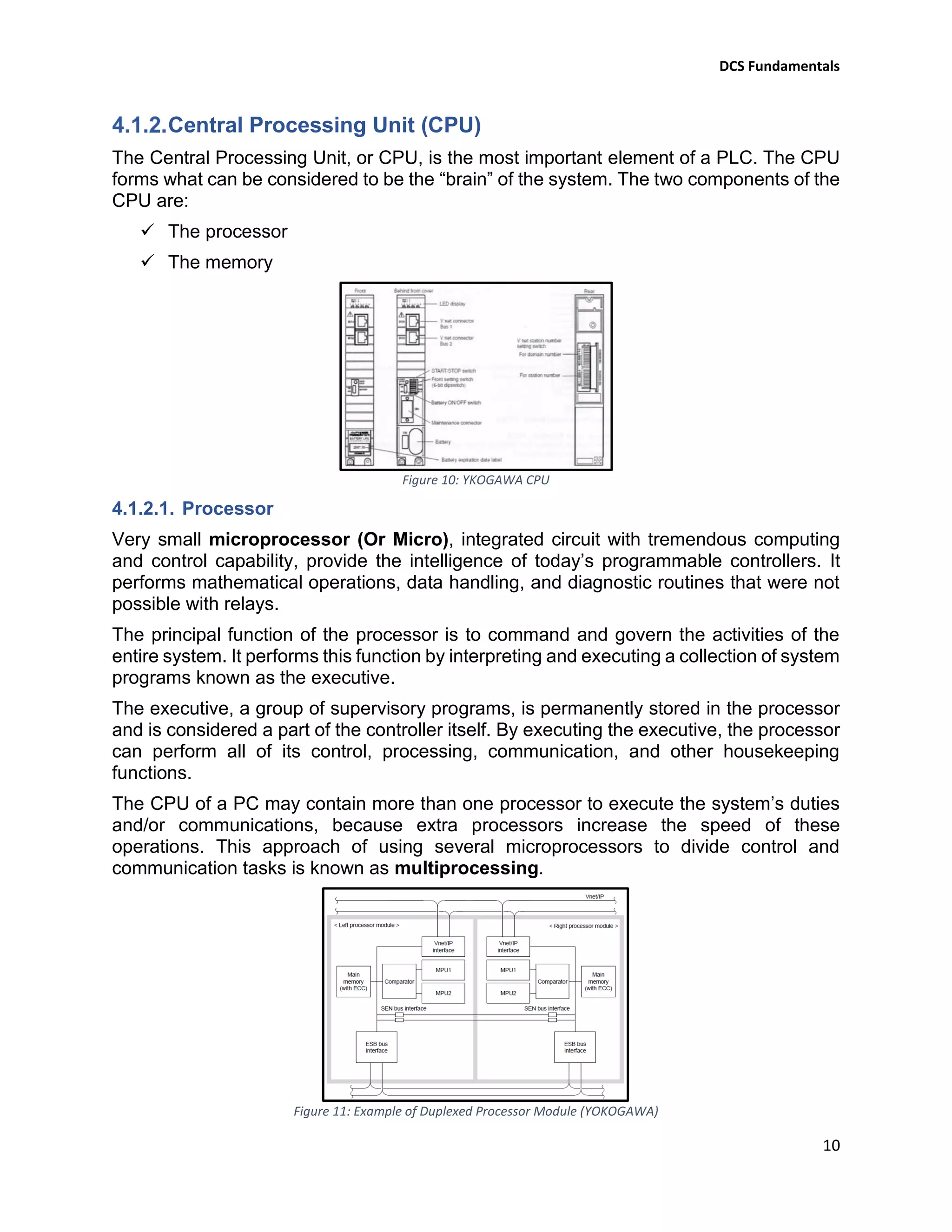
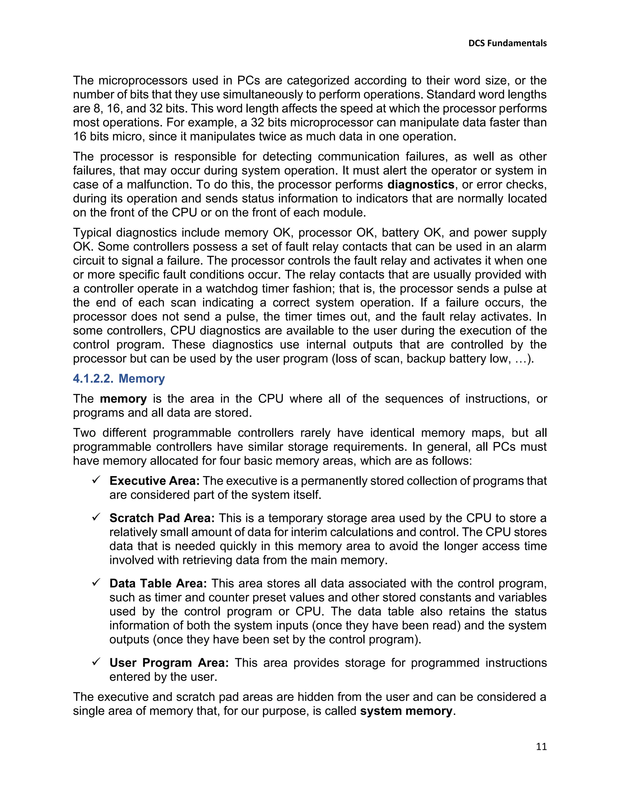
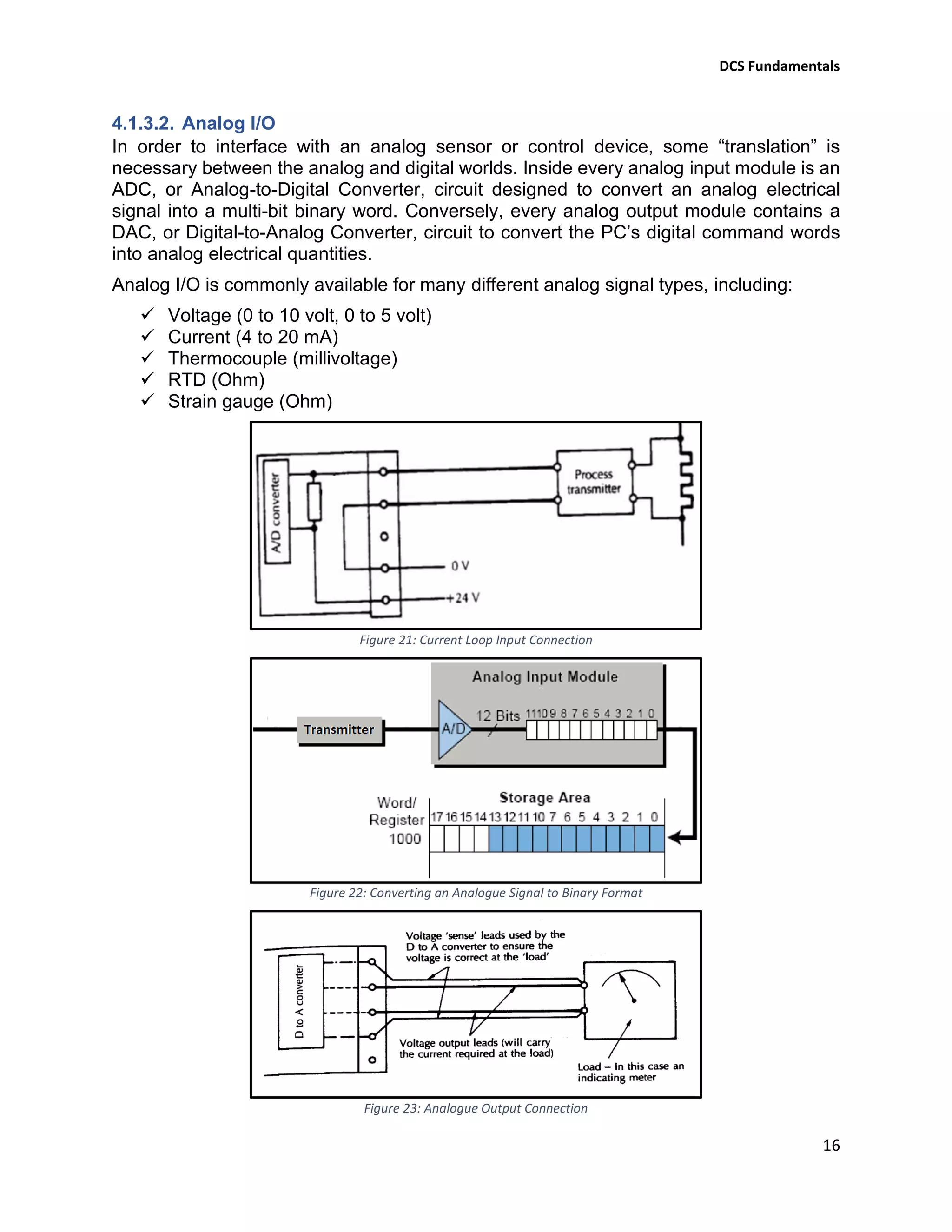
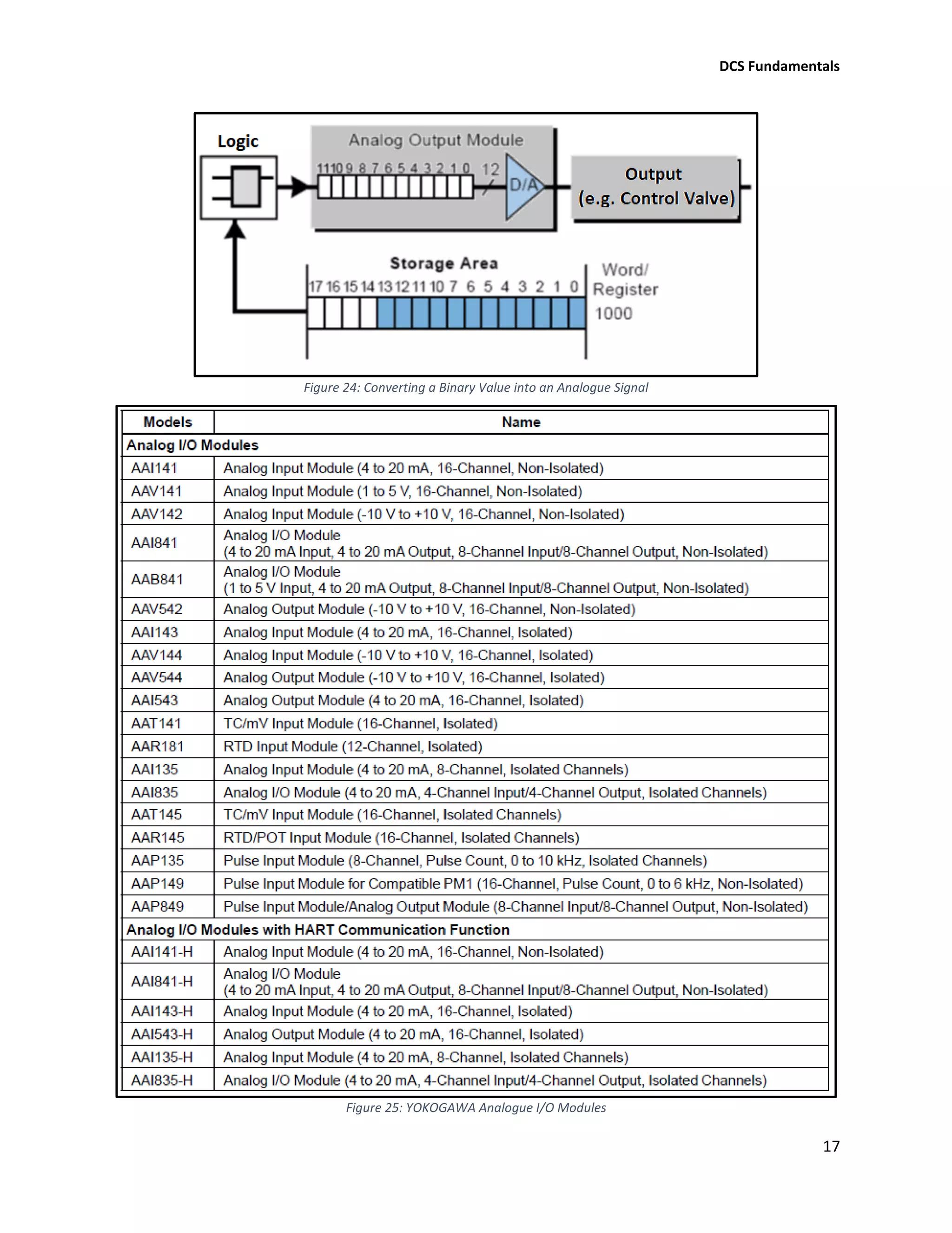
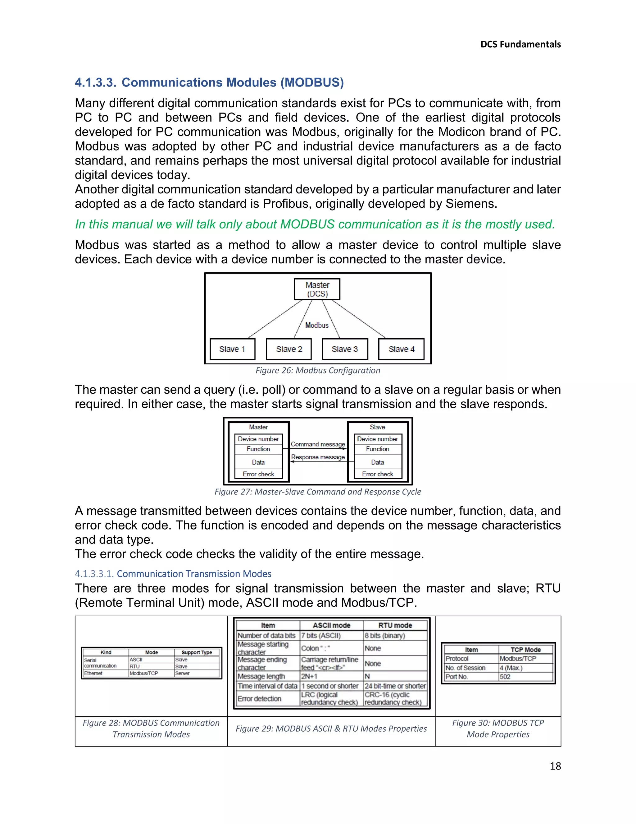
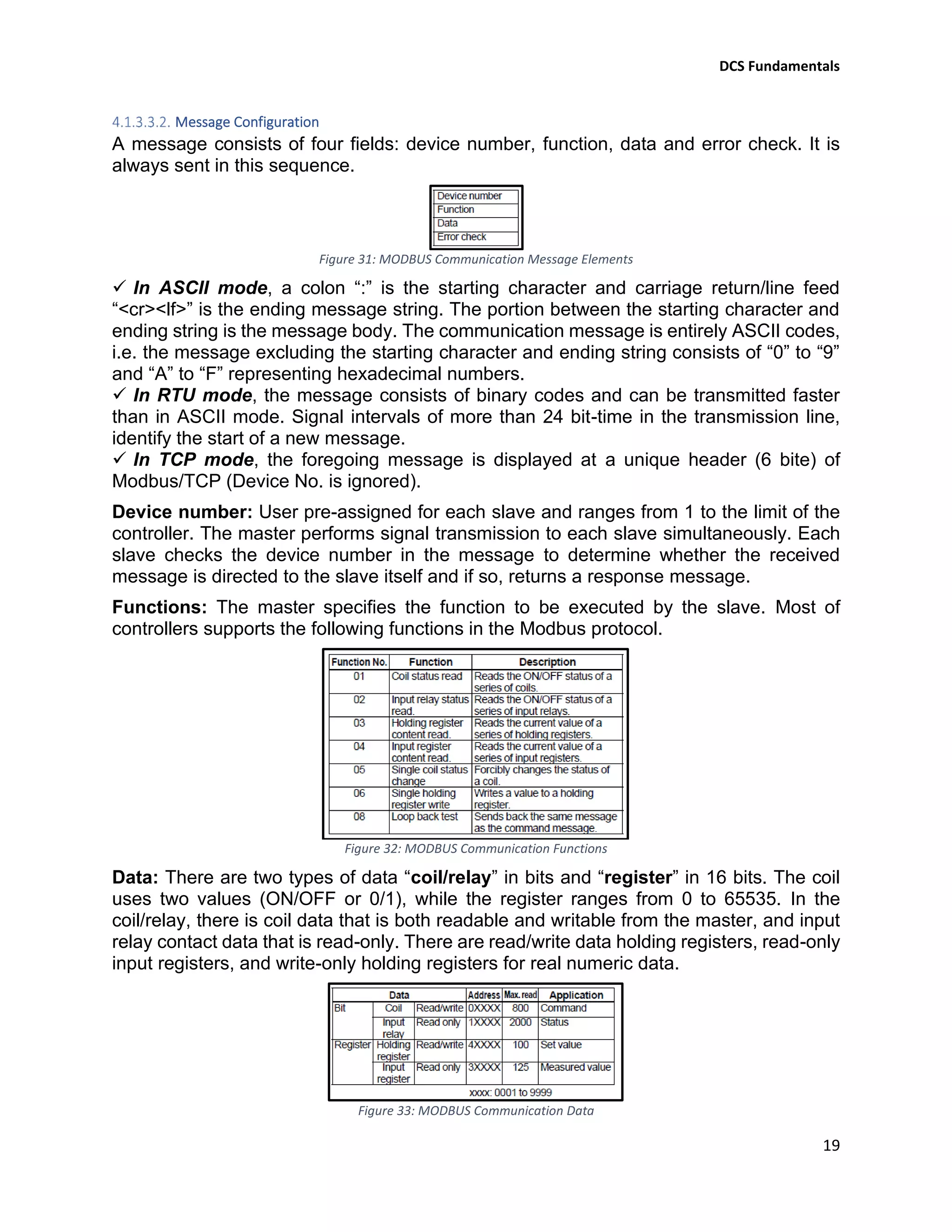
Othmane El Ahrache
2020
DCS Fundamentals
DCS Fundamentals
1
Table of Contents
1. Introduction........................................................................................................ 5
2. What is DCS? .................................................................................................... 6
Control System .............................................................................................................................6
Distributed Control System (DCS).................................................................................................6
3. DCS Architecture ............................................................................................... 7
4. Basic Elements of Distributed Control System................................................... 8
Distributed Controller (Local Control Unit) ..................................................................................8
Power Supply Module...................................................................................................................8
Central Processing Unit (CPU) ....................................................................................................10
4.1.2.1. Processor ....................................................................................................................................10
4.1.2.2. Memory ......................................................................................................................................11
4.1.2.3. Processor Scan Cycle ..................................................................................................................12
Input / Output Modules..............................................................................................................12
4.1.3.1. Discrete I/O.................................................................................................................................13
4.1.3.2. Analog I/O...................................................................................................................................16
4.1.3.3. Communications Modules (MODBUS) .......................................................................................18
Communication Transmission Modes.........................................................................................18
Message Configuration...............................................................................................................19
Slave Response............................................................................................................................20
Serial Communication Specifications..........................................................................................21
Serial Communication Wiring .....................................................................................................21
Engineering Working Station......................................................................................................22
Human Interface Station ............................................................................................................25
Network......................................................................................................................................28
Redundancy................................................................................................................................28
5. Logic Programming.......................................................................................... 28
Ladder Diagram (LD)...................................................................................................................28
LD Symbols:.................................................................................................................................29
Example (Level Control)..............................................................................................................30
Structured Text (ST)....................................................................................................................31
ST Operators & Instructions .......................................................................................................31
Example (Converting LD to ST) ...................................................................................................31
DCS Fundamentals
2
Instruction List (IL)......................................................................................................................32
Modifiers and operators in IL .....................................................................................................32
Example (Converting LD to IL) ....................................................................................................33
Function Block Diagram (FBD)....................................................................................................33
Example of simple control loop (YOKOGAWA)...........................................................................33
Sequential Function Chart (SFC).................................................................................................34
Steps ...........................................................................................................................................34
Actions........................................................................................................................................34
Transition/Transition condition..................................................................................................34
6. System Maintenance and Troubleshooting...................................................... 35
Field Instrument Maintenance...................................................................................................35
Precautions for Static Electricity.................................................................................................35
Daily Maintenance......................................................................................................................35
Replacing Power supply module ................................................................................................35
Procedure for Removing power supply modules.......................................................................35
Procedure for Installing power supply modules.........................................................................35
Replacing Processor module ......................................................................................................36
Procedure for Removing processor modules .............................................................................36
Procedure for Installing processor modules...............................................................................36
Replacing Battery........................................................................................................................36
Backup ........................................................................................................................................36
Power Outage.............................................................................................................................36
7. Advantages Disadvantages of DCS................................................................. 36
Advantages of DCS......................................................................................................................36
Disadvantages of DCS .................................................................................................................37
DCS Fundamentals
3
Table of Figures
Figure 1: Typical Control System in Industry 6
Figure 2: Typical Distributed Control System (DCS) 6
Figure 3: Typical DCS Architecture 7
Figure 4: Yokogawa DCS Architecture 7
Figure 5: Basic Programmable Controller Structure 8
Figure 6: Basic DCS Controller Rack & YOKOGAWA RACK (Node) 8
Figure 7: Yokogawa Power Supply Unit (PSU) 8
Figure 8: Uninterruptible Power Supply (UPS) Bloc Diagram 9
Figure 9: Power Supply Distribution to Racks Power Supply Modules 9
Figure 10: YKOGAWA CPU 10
Figure 11: Example of Duplexed Processor Module (YOKOGAWA) 10
Figure 12:A Simplified Memory Map 12
Figure 13: Programmable Controller Total Scan Cycle Representation 12
Figure 14: I/O Modules Fixed Inside Rack 12
Figure 15: Link Between Master Rack and Extension Racks 13
Figure 16: Internal Schematic Diagram for a Discrete Input Module 13
Figure 17: Converting a Discrete Signal to Binary Format 14
Figure 18: Internal Schematic Diagram for a Discrete Output Module 14
Figure 19: Converting a Binary Format to Discrete Signal 15
Figure 20: YOKOGAWA Discrete I/O Modules 15
Figure 21: Current Loop Input Connection 16
Figure 22: Converting an Analogue Signal to Binary Format 16
Figure 23: Analogue Output Connection 16
Figure 24: Converting a Binary Value into an Analogue Signal 17
Figure 25: YOKOGAWA Analogue I/O Modules 17
Figure 26: Modbus Configuration 18
Figure 27: Master-Slave Command and Response Cycle 18
Figure 28: MODBUS Communication Transmission Modes 18
Figure 29: MODBUS ASCII & RTU Modes Properties 18
Figure 30: MODBUS TCP Mode Properties 18
Figure 31: MODBUS Communication Message Elements 19
Figure 32: MODBUS Communication Functions 19
Figure 33: MODBUS Communication Data 19
Figure 34: Slave Error Response in MODBUS Communication 20
Figure 35: Error Codes in MODBUS Communication 20
Figure 36: YOKOGAWA Communication Module Terminals Names 21
Figure 37: YOKOGAWA RS485 Connection Wiring 21
Figure 38: YOKOGAWA RS232 Connection Wiring 21
Figure 39: EWS (Project Creation) 22
Figure 40: EWS (Users Registration) 22
Figure 41: EWS (Programmable Controller Creation) 23
Figure 42: EWS (Operation & Monitoring Station Creation) 23
DCS Fundamentals
4
Figure 43: EWS (I/O Modules Creation) 23
Figure 44: EWS (Graphic Windows Creation) 24
Figure 45: EWS (Program Configuration) 24
Figure 46: EWS (System Download) 24
Figure 47: HIS (Overview Window) 25
Figure 48: HIS (Graphic Window) 25
Figure 49: HIS (Faceplate Window) 26
Figure 50: HIS (Tuning Window) 26
Figure 51: HIS (Trend Window) 26
Figure 52: HIS (Process Alarms Window) 27
Figure 53: HIS (System Alarms Window) 27
Figure 54: HIS (System Status Window) 27
Figure 55: Ladder Diagram Execution Direction 29
Figure 56: Ladder Diagram Symbols 29
Figure 57: Level Control Design 30
Figure 58: Level Control Ladder Logic Diagram 30
Figure 59: ST programming Language Operators 31
Figure 60: Operators in IL with Their Possible Modifiers 32
Figure 61: Simple Control Loop Configured by YOKOGAWA PID Functional Block 33
Figure 62: YOKOGAWA PID Functional Block Details 33
Figure 63: SFC Main Components 34
Figure 64: SFC Design Structures 34
DCS Fundamentals
5
1. Introduction
The process control of large industrial plants has evolved through many stages. Initially,
control would be from panels local to the process plant. However, this required a large
manpower resource to attend to these dispersed panels, and there was no overall view
of the process. The next logical development was the transmission of all plant
measurements to a permanently-manned central control room. Effectively this was the
centralization of all the localized panels, with the advantages of lower manning levels and
easier overview of the process. Often the controllers were behind the control room panels,
and all automatic and manual control outputs were transmitted back to plant. However,
whilst providing a central control focus, this arrangement was inflexible as each control
loop had its own controller hardware, and continual operator movement within the control
room was required to view different parts of the process.
With the coming of electronic processors and graphic displays it became possible to
replace these discrete controllers with computer-based algorithms, hosted on a network
of input/output racks with their own control processors. These could be distributed around
plant, and communicate with the graphic display in the control room or rooms. The
distributed control system was born.
The introduction of DCSs allowed easy interconnection and re-configuration of plant
controls such as cascaded loops and interlocks, and easy interfacing with other
production computer systems. It enabled sophisticated alarm handling, introduced
automatic event logging, removed the need for physical records such as chart recorders,
allowed the control racks to be networked and thereby located locally to plant to reduce
cabling runs, and provided high level overviews of plant status and production levels.
The aim of this manual is to introduce, in simple terms, what is meant by DCS in
instrument control systems.
DCS Fundamentals
6
2. What is DCS?
Control System
A Control System is a device, or set of devices, that manages, commands, directs or
regulates the behavior of other devices or systems using control loops.
Figure 1: Typical Control System in Industry
Distributed Control System (DCS)
Distributed Control System (DCS) is a specially designed control system used to
control complex, large, and geographically distributed applications in industrial
processes, that means that the control of a plant is split into small units which are
distributed around the plant.
Figure 2: Typical Distributed Control System (DCS)
Figure 2 shows a simple DCS system. The plant consists of three separate (Distributed)
local control units: fractionation, compression and boiler. The loops for each unit are
controlled by a local control unit. The information required by the operator is sent by a
single cable (Data highway) to the central control room. Here, the information is shown
on a workstation. The operator can adjust the set points, control the valves and start or
stop the motors etc..., from the workstation using the same data highway.
DCS Fundamentals
7
There are various manufacturers of DCS's, ADNOC Gas processing company use a
variety of these systems (Centum VP (Yokogawa), Experion PKS (Honeywell), Delta-v
(Emerson)), in this manual Yokogawa system is taken as example.
3. DCS Architecture
In DCS, controllers are distributed throughout the entire plant area. These distributed
controllers are connected together and to operating PCs through high-speed
communication networks and connected to field instruments through instrument cables
as shown below in the figure 3.
Figure 3: Typical DCS Architecture
Figure 4: Yokogawa DCS Architecture
FCS: Field Control Station.
HIS: Human Interface Station.
ENG: Engineering Work Station.
Vnet/IP: Yokogawa Control Network
DCS Fundamentals
8
4. Basic Elements of Distributed Control System
Distributed Controller (Local Control Unit)
Figure 5: Basic Programmable Controller Structure
The programmable controller (PC) contain basically power supply, CPU and I/O modules
placed into a rack encloser.
Figure 6: Basic DCS Controller Rack & YOKOGAWA RACK (Node)
Power Supply Module
The power supply module plays a major role in the total system operation. In fact, it can
be considered the “first-line manager” of system reliability and integrity. Its responsibility
is not only to provide necessary DC voltage levels required to the system components
(processor, memory, and input/output modules), but also to monitor and regulate the
supplied voltages and warn the CPU if something is wrong. The power supply, then, has
the function of supplying well-regulated power and protection for other system
components.
Figure 7: Yokogawa Power Supply Unit (PSU)
DCS Fundamentals
9
The power supply module takes the incoming voltage (usually 120 or 240 VAC) from an
uninterruptible power Supply (UPS) and change it as required (usually 5 to 32 VDC).
Figure 8: Uninterruptible Power Supply (UPS) Bloc Diagram
Figure 9: Power Supply Distribution to Racks Power Supply Modules
DCS Fundamentals
10
Central Processing Unit (CPU)
The Central Processing Unit, or CPU, is the most important element of a PLC. The CPU
forms what can be considered to be the “brain” of the system. The two components of the
CPU are:
✓ The processor
✓ The memory
Figure 10: YKOGAWA CPU
4.1.2.1. Processor
Very small microprocessor (Or Micro), integrated circuit with tremendous computing
and control capability, provide the intelligence of today’s programmable controllers. It
performs mathematical operations, data handling, and diagnostic routines that were not
possible with relays.
The principal function of the processor is to command and govern the activities of the
entire system. It performs this function by interpreting and executing a collection of system
programs known as the executive.
The executive, a group of supervisory programs, is permanently stored in the processor
and is considered a part of the controller itself. By executing the executive, the processor
can perform all of its control, processing, communication, and other housekeeping
functions.
The CPU of a PC may contain more than one processor to execute the system’s duties
and/or communications, because extra processors increase the speed of these
operations. This approach of using several microprocessors to divide control and
communication tasks is known as multiprocessing.
Figure 11: Example of Duplexed Processor Module (YOKOGAWA)
DCS Fundamentals
11
The microprocessors used in PCs are categorized according to their word size, or the
number of bits that they use simultaneously to perform operations. Standard word lengths
are 8, 16, and 32 bits. This word length affects the speed at which the processor performs
most operations. For example, a 32 bits microprocessor can manipulate data faster than
16 bits micro, since it manipulates twice as much data in one operation.
The processor is responsible for detecting communication failures, as well as other
failures, that may occur during system operation. It must alert the operator or system in
case of a malfunction. To do this, the processor performs diagnostics, or error checks,
during its operation and sends status information to indicators that are normally located
on the front of the CPU or on the front of each module.
Typical diagnostics include memory OK, processor OK, battery OK, and power supply
OK. Some controllers possess a set of fault relay contacts that can be used in an alarm
circuit to signal a failure. The processor controls the fault relay and activates it when one
or more specific fault conditions occur. The relay contacts that are usually provided with
a controller operate in a watchdog timer fashion; that is, the processor sends a pulse at
the end of each scan indicating a correct system operation. If a failure occurs, the
processor does not send a pulse, the timer times out, and the fault relay activates. In
some controllers, CPU diagnostics are available to the user during the execution of the
control program. These diagnostics use internal outputs that are controlled by the
processor but can be used by the user program (loss of scan, backup battery low, …).
4.1.2.2. Memory
The memory is the area in the CPU where all of the sequences of instructions, or
programs and all data are stored.
Two different programmable controllers rarely have identical memory maps, but all
programmable controllers have similar storage requirements. In general, all PCs must
have memory allocated for four basic memory areas, which are as follows:
✓ Executive Area: The executive is a permanently stored collection of programs that
are considered part of the system itself.
✓ Scratch Pad Area: This is a temporary storage area used by the CPU to store a
relatively small amount of data for interim calculations and control. The CPU stores
data that is needed quickly in this memory area to avoid the longer access time
involved with retrieving data from the main memory.
✓ Data Table Area: This area stores all data associated with the control program,
such as timer and counter preset values and other stored constants and variables
used by the control program or CPU. The data table also retains the status
information of both the system inputs (once they have been read) and the system
outputs (once they have been set by the control program).
✓ User Program Area: This area provides storage for programmed instructions
entered by the user.
The executive and scratch pad areas are hidden from the user and can be considered a
single area of memory that, for our purpose, is called system memory.
DCS Fundamentals
12
On the other hand, the data table and user program areas are accessible and are required
by the user for control applications. They are called application memory.
Figure 12:A Simplified Memory Map
4.1.2.3. Processor Scan Cycle
The scan cycle is the process of a programmable controller reading its inputs, executing
the configured logic, update its outputs and run some system diagnostics and other
communications as applicable at its manufacturer design.
Figure 13: Programmable Controller Total Scan Cycle Representation
The amount of time it takes for the PC to make a scan cycle is called scan time of the
controller. A typical Scan time for an DCS controller will vary from a few hundreds of a
millisecond to 1 seconds.
Input / Output Modules
Every programmable controller must have some means of receiving and interpreting
signals from field instruments such as switches, and transmitters, and also be able to
effect control over field control elements such as solenoids, control valves, and motors.
This is generally known as Input/Output, or I/O, modules that are built into a modular
(“rack”) divided on slot as shown below in the figure 14.
Figure 14: I/O Modules Fixed Inside Rack
DCS Fundamentals
13
An I/O module is a plug-in–type assembly and replaceable for the fact that individual
cards may be easily replaced in the event of failure without having to replace the entire
controller. Specific I/O modules may be chosen for custom applications, biasing toward
discrete cards for applications using many on/off inputs and outputs, or biasing toward
analog cards for applications using many 4-20 mA and similar signals.
As the programmable controllers have the ability to connect to processor-less racks
(Extension racks) filled with additional I/O modules, thus providing a way to increase the
number of I/O channels beyond the capacity of the base (Master) unit.
Figure 15: Link Between Master Rack and Extension Racks
Input/output modules for programmable controllers comes in three basic varieties:
✓ Discrete (Digital)
✓ Analog
✓ Communication
4.1.3.1. Discrete I/O
A “discrete” data point is one with only two states on and off. Process switches,
pushbutton switches, limit switches, and proximity switches are all examples of discrete
sensing devices. In order for a programmable controller to be aware of a discrete sensor’s
state, it must receive a signal from the sensor through a discrete input channel. Inside
each discrete input module is (typically) a set of light-emitting diodes (LEDs) which will be
energized when the corresponding sensing device turns on. Light from each LED shines
on a photo-sensitive device such as a phototransistor inside the module, which in turn
activates a bit (a single element of digital data) inside the PC’s memory. This opto-coupled
arrangement makes each input channel of a PC rather rugged, capable of isolating the
sensitive computer circuitry of the PC from transient voltage “spikes” and other electrical
phenomena capable of causing damage:
Figure 16: Internal Schematic Diagram for a Discrete Input Module
DCS Fundamentals
14
Energizing an input channel lights the LED inside the optocoupler, turning on the
phototransistor, sending a "high" signal to the PC’s microprocessor, setting (1) that bit in
the input register.
The internal schematic diagram for a discrete input module (“card”) shown in figure 16
reveals the componentry typical for a single input channel on that card. Each input
channel has its own optocoupler, writing to its own unique memory register bit inside the
PC’s memory. Discrete input cards for PCs typically have 16, 32, Or 64 channels.
Figure 17: Converting a Discrete Signal to Binary Format
Indicator lamps, solenoid valves, and motor starters (assemblies consisting of contactors
and overload protection devices) are all examples of discrete control devices. In a manner
similar to discrete inputs, a PC connects to any number of different discrete final control
devices through a discrete output channel. Discrete output modules typically use the
same form of opto-isolation to allow the PC’s circuitry to send electrical power to loads:
the internal PC circuitry driving an LED which then activates a photosensitive switching
device. Alternatively, small electromechanical relays may be used in lieu of opto-isolating
semiconductor switching elements such as transistors (DC) or TRIACs (AC):
Figure 18: Internal Schematic Diagram for a Discrete Output Module
Setting a bit (1) in the PC’s output register sends a "high" signal to the LED inside the
optocoupler, turning on the photo-TRIAC, sending AC power to the output channel to
energize the load.
DCS Fundamentals
15
As with the schematic diagram for a discrete input module shown previously, the
schematic diagram for a discrete output module reveals the componentry typical for a
single channel on that card. Each output channel has its own optocoupler, driven by its
own unique memory register bit inside the PC’s memory. Discrete output cards for PCs
also typically have 4, 16, 32 or 64 channels.
Figure 19: Converting a Binary Format to Discrete Signal
Figure 20: YOKOGAWA Discrete I/O Modules
DCS Fundamentals
16
4.1.3.2. Analog I/O
In order to interface with an analog sensor or control device, some “translation” is
necessary between the analog and digital worlds. Inside every analog input module is an
ADC, or Analog-to-Digital Converter, circuit designed to convert an analog electrical
signal into a multi-bit binary word. Conversely, every analog output module contains a
DAC, or Digital-to-Analog Converter, circuit to convert the PC’s digital command words
into analog electrical quantities.
Analog I/O is commonly available for many different analog signal types, including:
✓ Voltage (0 to 10 volt, 0 to 5 volt)
✓ Current (4 to 20 mA)
✓ Thermocouple (millivoltage)
✓ RTD (Ohm)
✓ Strain gauge (Ohm)
Figure 21: Current Loop Input Connection
Figure 22: Converting an Analogue Signal to Binary Format
Figure 23: Analogue Output Connection
DCS Fundamentals
17
Figure 24: Converting a Binary Value into an Analogue Signal
Figure 25: YOKOGAWA Analogue I/O Modules
DCS Fundamentals
18
4.1.3.3. Communications Modules (MODBUS)
Many different digital communication standards exist for PCs to communicate with, from
PC to PC and between PCs and field devices. One of the earliest digital protocols
developed for PC communication was Modbus, originally for the Modicon brand of PC.
Modbus was adopted by other PC and industrial device manufacturers as a de facto
standard, and remains perhaps the most universal digital protocol available for industrial
digital devices today.
Another digital communication standard developed by a particular manufacturer and later
adopted as a de facto standard is Profibus, originally developed by Siemens.
In this manual we will talk only about MODBUS communication as it is the mostly used.
Modbus was started as a method to allow a master device to control multiple slave
devices. Each device with a device number is connected to the master device.
Figure 26: Modbus Configuration
The master can send a query (i.e. poll) or command to a slave on a regular basis or when
required. In either case, the master starts signal transmission and the slave responds.
Figure 27: Master-Slave Command and Response Cycle
A message transmitted between devices contains the device number, function, data, and
error check code. The function is encoded and depends on the message characteristics
and data type.
The error check code checks the validity of the entire message.
Communication Transmission Modes
There are three modes for signal transmission between the master and slave; RTU
(Remote Terminal Unit) mode, ASCII mode and Modbus/TCP.
Figure 28: MODBUS Communication
Transmission Modes
Figure 29: MODBUS ASCII & RTU Modes Properties
Figure 30: MODBUS TCP
Mode Properties
DCS Fundamentals
19
Message Configuration
A message consists of four fields: device number, function, data and error check. It is
always sent in this sequence.
Figure 31: MODBUS Communication Message Elements
✓ In ASCII mode, a colon “:” is the starting character and carriage return/line feed
“<cr><lf>” is the ending message string. The portion between the starting character and
ending string is the message body. The communication message is entirely ASCII codes,
i.e. the message excluding the starting character and ending string consists of “0” to “9”
and “A” to “F” representing hexadecimal numbers.
✓ In RTU mode, the message consists of binary codes and can be transmitted faster
than in ASCII mode. Signal intervals of more than 24 bit-time in the transmission line,
identify the start of a new message.
✓ In TCP mode, the foregoing message is displayed at a unique header (6 bite) of
Modbus/TCP (Device No. is ignored).
Device number: User pre-assigned for each slave and ranges from 1 to the limit of the
controller. The master performs signal transmission to each slave simultaneously. Each
slave checks the device number in the message to determine whether the received
message is directed to the slave itself and if so, returns a response message.
Functions: The master specifies the function to be executed by the slave. Most of
controllers supports the following functions in the Modbus protocol.
Figure 32: MODBUS Communication Functions
Data: There are two types of data “coil/relay” in bits and “register” in 16 bits. The coil
uses two values (ON/OFF or 0/1), while the register ranges from 0 to 65535. In the
coil/relay, there is coil data that is both readable and writable from the master, and input
relay contact data that is read-only. There are read/write data holding registers, read-only
input registers, and write-only holding registers for real numeric data.
Figure 33: MODBUS Communication Data
DCS Fundamentals
20
Error check: All messages are followed by an error check code to detect a Signal
transmission error (i.e. bit changes). In ASCII mode, an error check code according to
LRC (logical redundancy check) is used. In RTU mode, an error check code according to
CRC-16 (cyclic redundancy check) is used.
Slave Response
Normal response: For the single coil status change, single holding register write, and
loop back function, the same message as the command message is sent back. As a
response message, the read function returns the retrieved data appended to the device
number and function code. If an address to which data is not allocated is read, an error
is not generated but zero (0) is responded as the read data.
Error response: If the command message is faulty, the slave does not execute the
command but sends back an error response.
The master can check whether the command is accepted successfully by checking the
function in the response message. If an error is identified, the details can be checked
from the error code.
In addition, access to the data consisting of several registers will return an error unless
the correct start address of data has been given. Therefore, the correct data boundary
must be specified.
Figure 34: Slave Error Response in MODBUS Communication
Figure 35: Error Codes in MODBUS Communication
No response: In the following cases, the slave ignores the command message and does
not send back a response (no response).
✓ When a transmission error (overrun, framing error, parity error or CRC error) is
detected in the command message
✓ When the device number in the command message does not match the slave
number assigned to the slave.
Note: The master should set a timer to watch the response from the slave, and re-send
the same command or the message to the slave when the slave does not respond within
the time set by the timer.
DCS Fundamentals
21
Serial Communication Specifications
Transmission mode : ASCII mode/RTU mode
Communication standard : RS-232, RS-422, RS-485
Transmission : - Half duplex for RS-232 & RS-422 (2-wires system)
- Full duplex (RS-422, RS-485, 4-wires system)
Start-stop synchronization : - (ASCII) 1 start bit, 7 data bits, 1 parity bit, 1 stop bit
- (RTU) 1 start bit, 8 data bits, 1 parity bit, 1 stop bit
Communication speed : 1200/2400/4800/9600/19200/38400 bps (Selectable)
Parity check : Odd /even /none (Selectable)
Maximum length : As per manufacturer design (1Km for YOKOGAWA)
Note:
✓ Any mismatch between the master and slave will result in no communication.
✓ Once the connection of Modbus/TCP is established, be sure to keep it connected.
Frequent connection/disconnection may cause an error in communication
operation.
Serial Communication Wiring
Figure 36: YOKOGAWA Communication Module Terminals Names
Figure 37: YOKOGAWA RS485 Connection Wiring
Figure 38: YOKOGAWA RS232 Connection Wiring
DCS Fundamentals
22
Engineering Working Station
Engineering work station is a computer loaded with engineering software, it is mainly used
to perform system generation, configuration and maintenance management.
Some functions of the YOKOGAWA engineering software are illustrated below:
Project Creation: A project is the unit of managing system configuration database
containing the configuration information for all stations in the system.
Figure 39: EWS (Project Creation)
Users Registration: Specify user names, Users groups and security privilege levels.
Figure 40: EWS (Users Registration)
DCS Fundamentals
23
Control Station Creation: Create the programmable controller by selecting the type and
defining all required properties.
Figure 41: EWS (Programmable Controller Creation)
Operation & Monitoring Station Creation: Creation of new human interface station with all
required properties (type, number, network and so on).
Figure 42: EWS (Operation & Monitoring Station Creation)
I/O Modules Creation: Create I/O Module folder in the control station folder may be used to
create or add the required inputs and outputs.
Figure 43: EWS (I/O Modules Creation)
DCS Fundamentals
24
Graphic Windows Creation: Create windows to be used for graphic pages design and
animation.
Figure 44: EWS (Graphic Windows Creation)
Program Configuration: Create program as per the logic diagram and the control narrative.
Figure 45: EWS (Program Configuration)
System Download: Download system data base to the control stations.
Figure 46: EWS (System Download)
DCS Fundamentals
25
Human Interface Station
The Human Interface Station (HIS) or Human Machine Interface (HMI) is mainly used for
operation and monitoring, it displays process variables, control parameters, and alarms
necessary for users to quickly grasp the operating status of the plant. It also incorporates
open interfaces so that supervisory computers can access trend data, messages, and
process data.
Some YOKOGAWA displays are illustrated below:
Overview Window: Graphic window used as menu to access all monitoring windows of
overall plant.
Figure 47: HIS (Overview Window)
Graphic Window: Created by the user and animated in order to recognize visually the
state of the process control.
Figure 48: HIS (Graphic Window)
DCS Fundamentals
26
Faceplate Window: Instrument interface.
Figure 49: HIS (Faceplate Window)
Tuning Window: Displays the control status of the function block. It is also used for tuning
the various control parameters.
Figure 50: HIS (Tuning Window)
Trend Window: Acquires different types of process data and displays time-series change
in a graph.
Figure 51: HIS (Trend Window)
DCS Fundamentals
27
Process Alarms Window: Displays process alarms in the order they are generated
starting with the most recent alarm.
Figure 52: HIS (Process Alarms Window)
System Alarms Window: Displays system alarm messages to notify the user of system
hardware (Stations down, card error etc…) in the order with the most recent ones first.
Figure 53: HIS (System Alarms Window)
System Status Window: Displays controllers, cards and network status.
Figure 54: HIS (System Status Window)
DCS Fundamentals
28
Network
Real-time (High speed) control system bus links that all stations such as Control stations,
EWSs, HISs with high security.
Redundancy
The Mean time between failures (MTBF) of any system dependent upon certain critical
components may be extended by duplicating those components in parallel fashion, such
that the failure of only one does not compromise the system as a whole. This is
called redundancy.
A common example of component redundancy in instrumentation and control systems is
the redundancy offered by DCS, where processors, network cables, and even I/O
(input/output) modules may be equipped with “hot standby” duplicates ready to assume
functionality in the event the primary component fails.
Redundancy tends to extend the MTBF of a system without necessarily extending its
service life. A DCS equipped with redundant microprocessor control modules in its rack,
will exhibit a greater MTBF because a random microprocessor fault will be covered by the
presence of the spare (“hot standby”) microprocessor module.
However, given the fact that both microprocessors are continually powered, and therefore
tend to “wear” at the same rate, their operating lives will not be additive. In other words,
two microprocessors will not function twice as long before wear-out than one
microprocessor.
The extension of MTBF resulting from redundancy holds true only if the random failures
are truly independent events, that is, not associated by a common cause.
5. Logic Programming
Although it seems each model of PC has its own standard for programming, there does
exist an international standard for controller programming that most PC manufacturers at
least attempt to conform to. This is the IEC 61131-3 standard.
One should take solace in the fact that despite differences in the details of PC
programming from one manufacturer to another and from one model to another, the basic
principles are largely the same.
The IEC 61131-3 standard specifies five distinct forms of programming language for
industrial controllers:
✓ Ladder Diagram (LD)
✓ Structured Text (ST)
✓ Instruction List (IL)
✓ Function Block Diagram (FBD)
✓ Sequential Function Chart (SFC)
Ladder Diagram (LD)
The ladder diagram consists of two vertical lines representing the power rails. Circuits are
connected as horizontal lines, i.e., the rungs of the ladder, between these two verticals.
DCS Fundamentals
29
In drawing a ladder diagram, certain conventions are adopted:
1. The vertical lines of the diagram represent the power rails between which circuits
are connected.
2. Each rung on the ladder defines one operation in the control process.
3. A ladder diagram is read from left to right and from top to bottom.
Figure 55: Ladder Diagram Execution Direction
4. Each rung must start with an input or inputs and must end with at least one output.
5. The inputs and outputs are all identified by their addresses, the notation used
depending on the manufacturer. This is the address of the input or output in the
memory.
LD Symbols:
Figure 56: Ladder Diagram Symbols
DCS Fundamentals
30
Example (Level Control)
Figure 57: Level Control Design
If Auto mode selected, then pump will be logically controlled based on Low-Level switch
(LSL) and High-Level switch (LSH):
▪ Pump stop when the level reaches low-level or stop push button pressed.
▪ If the level of the liquid reaches high point, the pump will be started so that the liquid
can be drained and thus lowering the level.
If Manual mode selected then pump will be controlled by operator:
▪ Pump stop when the level reaches low-level or stop push button pressed.
▪ Pump will be started when start push button pressed.
Figure 58: Level Control Ladder Logic Diagram
DCS Fundamentals
31
Structured Text (ST)
The structured text consists of a series of instructions which, as determined in high level
languages, ("IF..THEN..ELSE") or in loops (WHILE..DO) can be executed.
Example:
IF value < 7 THEN
WHILE value < 8 DO
value := value + 1;
END_WHILE;
END_IF;
ST Operators & Instructions
Figure 59: ST programming Language Operators
You can build structured text programs using these statement types:
✓ Assignment - Assigning the value of a variable.
✓ Function Call - Call a function discarding the return value.
✓ RETURN - Return from a Program Unit early.
✓ IF - Execute statements if a condition is true (or false).
✓ CASE - Execute statements based on a selector value.
✓ FOR - Execute statements a defined number of times.
✓ WHILE - Execute statements while a condition is true.
✓ REPEAT - Execute statements until a condition is true.
✓ EXIT - Exit a loop early.
Example (Converting LD to ST)
Level Control Figure 57:
If (Start=1 OR M=1 OR (LSH=0 AND AM=1)) AND Stop=1 AND LSL =1 Then
M=1;
ELSE M=0;
END_IF;
DCS Fundamentals
32
Instruction List (IL)
An instruction list (IL) consists of a series of instructions. Each instruction begins in a new
line and contains an operator and, depending on the type of operation, one or more
operands separated by commas. In front of an instruction there can be an identification
mark (label) followed by a colon (:).
A comment must be the last element in a line. Empty lines can be inserted between
instructions.
Example:
LD TRUE (*load TRUE in the accumulator*)
ANDN BOOL1 (*execute AND with the negated value of the BOOL1 variable*)
JMPC label (*if the result was TRUE, then jump to the label "label"*)
LDN BOOL2 (*save the negated value of *)
ST ERG (*BOOL2 in ERG*)
label:
LD BOOL2 (*save the value of *)
ST ERG (*BOOL2 in ERG*)
Modifiers and operators in IL
Figure 60: Operators in IL with Their Possible Modifiers
✓ C with JMP, CAL, RET: The instruction is only then executed if the result of the
preceding expression is TRUE.
✓ N with JMPC, CALC, RETC: The instruction is only then executed if the result of
the preceding expression is FALSE.
✓ N otherwise: Negation of the operand (not of the accumulator)
DCS Fundamentals
33
Example (Converting LD to IL)
Function Block Diagram (FBD)
The Function Block Diagram (FBD) is a graphical programming language that can
describe the function between input variables and output variables.
Example of simple control loop (YOKOGAWA)
Figure 61: Simple Control Loop Configured by YOKOGAWA PID Functional Block
Figure 62: YOKOGAWA PID Functional Block Details
DCS Fundamentals
34
Sequential Function Chart (SFC)
The sequential function chart a graphically oriented language which makes it possible to
describe the chronological order of different actions within a program.
Main components of SFC are:
✓ Steps.
✓ Actions to be executed at every step.
✓ Transitions Conditions.
Figure 63: SFC Main Components
Steps
Steps in an SFC diagram can be active or inactive. Actions are only executed for active
steps. A step can be active for one of two motives:
✓ It is an initial step as specified by the programmer.
✓ It was activated during a scan cycle and not deactivated since.
Steps are activated when all steps above it are active and the connecting transition is
superable (i.e. its associated condition is true). When a transition is passed, all steps
above are deactivated at once and after all steps below are activated at once.
Actions
An action is a series of instructions in IL or in ST, a lot of networks in FBD or in LD, or
again in sequential function chart (SFC), it is always connected to a step.
Transition/Transition condition
A transition is the condition that must be “True” to pass from one step to another.
Figure 64: SFC Design Structures
DCS Fundamentals
35
6. System Maintenance and Troubleshooting
Field Instrument Maintenance
DCS relies on the transmitters reading, if the transmitter zero or span adjustment is not
accurately set up, then DCS will accept the received signal as being correct and poor
control, or an in-accurate data display will be the result.
Precautions for Static Electricity
System components are sensitive to damage from static electricity. The damage suffered
by a component may not be immediately obvious, as the effects can be cumulative; a
component suddenly failing in service for no apparent reason. In order to minimize this
risk, the following precautions should be observed wherever practicable:
✓ When storing or carrying a maintenance part, put it in an anti-static bag with a label
describing precautions for static electricity, when delivered.
✓ During maintenance, wear a wrist strap with grounding wire and ground the wire
via 1MΩ resistor.
✓ When placing a card with a built-in battery (Power Supply Unit) on conductive
sheet, set the battery switch to OFF or remove the battery.
Daily Maintenance
A monitoring station (EWS, HIS) always monitors the status of each element, and upon
occurrence of and recovery from a failure of stations or networks announces it to the user
with a buzzer sound and display message.
Also, the system engineer is carrying out daily routine inspection and reporting the
findings for the following:
✓ Controllers status
✓ Modules status
✓ Monitoring stations status
✓ Networks status
Replacing Power supply module
Procedure for Removing power supply modules
1. Confirm the other power supply module is working properly.
2. Switch off the circuit braker corresponding to the module to be removed.
3. Disconnect the module to be removed from the external power interface unit.
4. Remove the fixing screws of the power supply module.
5. Pull the power supply module forward and remove it from the base unit.
Procedure for Installing power supply modules
1. Install the power supply module on the base unit.
2. Fix the screws of the power supply module.
3. Insert the corresponding connector of the power supply module to the external
interface unit and switch on the corresponding circuit braker.
DCS Fundamentals
36
Replacing Processor module
Procedure for Removing processor modules
1. Confirm that the processor module to be removed is in standby state.
2. Remove the fixing screws of the processor module.
3. Pull the power supply module forward and remove it from the base unit.
Procedure for Installing processor modules
1. Confirm the new processor module sittings are the same as the replaced one.
2. Install the processor module on the base unit.
3. Fix the screws of the processor module.
4. Confirm the processor module is at normal state and completed copying the
program.
Replacing Battery
✓ Replace a battery pack when the validity period expires.
✓ Wear a wrist strap when handling a battery.
✓ Do not throw a battery pack in a fire.
✓ Do not disassemble a battery pack.
Backup
It is required to back up the system periodically and whenever any changes are carried
out.
Power Outage
If the power supply is interrupted to the DCS, the UPS system not maintaining the supply,
then the following state will occur:
✓ All modules will shut down.
✓ All data highway units will shut down.
✓ All outputs to control valves will go to 0mA; valves should be designed to go to a
fail-safe condition.
✓ All digital outputs will go to 0V; valves should be designed to go to a fail-safe
condition.
7. Advantages Disadvantages of DCS
Advantages of DCS
✓ The use of centralized control, with the whole plant able to be viewed and operated
through one central operator Interface window.
✓ Data presentation is in a systematic format enabling easy comparison of various
parameters.
✓ It is possible to control through dynamic graphic.
DCS Fundamentals
37
✓ Operator’s action can be logged, thereby eliminating confusion.
✓ The alarm system can be regrouped.
✓ Complex computations, analysis, etc. can be carried out easily.
✓ Management information can be generated at regular intervals.
✓ The super-imposed trends help in the analysis of plant parameters.
✓ Ease of introducing additional plant, additional controllers, process units or other
items that can be attached to the network at any time, within the constraints of
communications handling.
✓ Ease of commissioning. Small units of process can be commissioned individually
by linking them to a network and Operator interface, without the entire plant being
available.
Disadvantages of DCS
✓ The cost of installing a DCS may not be justified for small plant operations.
✓ All information and data presented in a systematic format is hidden behind the
CRT. Hence, it requires a skilled operator.
✓ In an emergency, decisions have to be taken single handedly, as few operators are
there in the control room.
✓ Failure of one controller effects more than one loop. Hence it calls for very high
MTBF (Mean Time Between Failures) and high degree of redundancy.

Dcs fundamentals

  • 1.
  • 2.
    DCS Fundamentals 1 Table ofContents 1. Introduction........................................................................................................ 5 2. What is DCS? .................................................................................................... 6 Control System .............................................................................................................................6 Distributed Control System (DCS).................................................................................................6 3. DCS Architecture ............................................................................................... 7 4. Basic Elements of Distributed Control System................................................... 8 Distributed Controller (Local Control Unit) ..................................................................................8 Power Supply Module...................................................................................................................8 Central Processing Unit (CPU) ....................................................................................................10 4.1.2.1. Processor ....................................................................................................................................10 4.1.2.2. Memory ......................................................................................................................................11 4.1.2.3. Processor Scan Cycle ..................................................................................................................12 Input / Output Modules..............................................................................................................12 4.1.3.1. Discrete I/O.................................................................................................................................13 4.1.3.2. Analog I/O...................................................................................................................................16 4.1.3.3. Communications Modules (MODBUS) .......................................................................................18 Communication Transmission Modes.........................................................................................18 Message Configuration...............................................................................................................19 Slave Response............................................................................................................................20 Serial Communication Specifications..........................................................................................21 Serial Communication Wiring .....................................................................................................21 Engineering Working Station......................................................................................................22 Human Interface Station ............................................................................................................25 Network......................................................................................................................................28 Redundancy................................................................................................................................28 5. Logic Programming.......................................................................................... 28 Ladder Diagram (LD)...................................................................................................................28 LD Symbols:.................................................................................................................................29 Example (Level Control)..............................................................................................................30 Structured Text (ST)....................................................................................................................31 ST Operators & Instructions .......................................................................................................31 Example (Converting LD to ST) ...................................................................................................31
  • 3.
    DCS Fundamentals 2 Instruction List(IL)......................................................................................................................32 Modifiers and operators in IL .....................................................................................................32 Example (Converting LD to IL) ....................................................................................................33 Function Block Diagram (FBD)....................................................................................................33 Example of simple control loop (YOKOGAWA)...........................................................................33 Sequential Function Chart (SFC).................................................................................................34 Steps ...........................................................................................................................................34 Actions........................................................................................................................................34 Transition/Transition condition..................................................................................................34 6. System Maintenance and Troubleshooting...................................................... 35 Field Instrument Maintenance...................................................................................................35 Precautions for Static Electricity.................................................................................................35 Daily Maintenance......................................................................................................................35 Replacing Power supply module ................................................................................................35 Procedure for Removing power supply modules.......................................................................35 Procedure for Installing power supply modules.........................................................................35 Replacing Processor module ......................................................................................................36 Procedure for Removing processor modules .............................................................................36 Procedure for Installing processor modules...............................................................................36 Replacing Battery........................................................................................................................36 Backup ........................................................................................................................................36 Power Outage.............................................................................................................................36 7. Advantages Disadvantages of DCS................................................................. 36 Advantages of DCS......................................................................................................................36 Disadvantages of DCS .................................................................................................................37
  • 4.
    DCS Fundamentals 3 Table ofFigures Figure 1: Typical Control System in Industry 6 Figure 2: Typical Distributed Control System (DCS) 6 Figure 3: Typical DCS Architecture 7 Figure 4: Yokogawa DCS Architecture 7 Figure 5: Basic Programmable Controller Structure 8 Figure 6: Basic DCS Controller Rack & YOKOGAWA RACK (Node) 8 Figure 7: Yokogawa Power Supply Unit (PSU) 8 Figure 8: Uninterruptible Power Supply (UPS) Bloc Diagram 9 Figure 9: Power Supply Distribution to Racks Power Supply Modules 9 Figure 10: YKOGAWA CPU 10 Figure 11: Example of Duplexed Processor Module (YOKOGAWA) 10 Figure 12:A Simplified Memory Map 12 Figure 13: Programmable Controller Total Scan Cycle Representation 12 Figure 14: I/O Modules Fixed Inside Rack 12 Figure 15: Link Between Master Rack and Extension Racks 13 Figure 16: Internal Schematic Diagram for a Discrete Input Module 13 Figure 17: Converting a Discrete Signal to Binary Format 14 Figure 18: Internal Schematic Diagram for a Discrete Output Module 14 Figure 19: Converting a Binary Format to Discrete Signal 15 Figure 20: YOKOGAWA Discrete I/O Modules 15 Figure 21: Current Loop Input Connection 16 Figure 22: Converting an Analogue Signal to Binary Format 16 Figure 23: Analogue Output Connection 16 Figure 24: Converting a Binary Value into an Analogue Signal 17 Figure 25: YOKOGAWA Analogue I/O Modules 17 Figure 26: Modbus Configuration 18 Figure 27: Master-Slave Command and Response Cycle 18 Figure 28: MODBUS Communication Transmission Modes 18 Figure 29: MODBUS ASCII & RTU Modes Properties 18 Figure 30: MODBUS TCP Mode Properties 18 Figure 31: MODBUS Communication Message Elements 19 Figure 32: MODBUS Communication Functions 19 Figure 33: MODBUS Communication Data 19 Figure 34: Slave Error Response in MODBUS Communication 20 Figure 35: Error Codes in MODBUS Communication 20 Figure 36: YOKOGAWA Communication Module Terminals Names 21 Figure 37: YOKOGAWA RS485 Connection Wiring 21 Figure 38: YOKOGAWA RS232 Connection Wiring 21 Figure 39: EWS (Project Creation) 22 Figure 40: EWS (Users Registration) 22 Figure 41: EWS (Programmable Controller Creation) 23 Figure 42: EWS (Operation & Monitoring Station Creation) 23
  • 5.
    DCS Fundamentals 4 Figure 43:EWS (I/O Modules Creation) 23 Figure 44: EWS (Graphic Windows Creation) 24 Figure 45: EWS (Program Configuration) 24 Figure 46: EWS (System Download) 24 Figure 47: HIS (Overview Window) 25 Figure 48: HIS (Graphic Window) 25 Figure 49: HIS (Faceplate Window) 26 Figure 50: HIS (Tuning Window) 26 Figure 51: HIS (Trend Window) 26 Figure 52: HIS (Process Alarms Window) 27 Figure 53: HIS (System Alarms Window) 27 Figure 54: HIS (System Status Window) 27 Figure 55: Ladder Diagram Execution Direction 29 Figure 56: Ladder Diagram Symbols 29 Figure 57: Level Control Design 30 Figure 58: Level Control Ladder Logic Diagram 30 Figure 59: ST programming Language Operators 31 Figure 60: Operators in IL with Their Possible Modifiers 32 Figure 61: Simple Control Loop Configured by YOKOGAWA PID Functional Block 33 Figure 62: YOKOGAWA PID Functional Block Details 33 Figure 63: SFC Main Components 34 Figure 64: SFC Design Structures 34
  • 6.
    DCS Fundamentals 5 1. Introduction Theprocess control of large industrial plants has evolved through many stages. Initially, control would be from panels local to the process plant. However, this required a large manpower resource to attend to these dispersed panels, and there was no overall view of the process. The next logical development was the transmission of all plant measurements to a permanently-manned central control room. Effectively this was the centralization of all the localized panels, with the advantages of lower manning levels and easier overview of the process. Often the controllers were behind the control room panels, and all automatic and manual control outputs were transmitted back to plant. However, whilst providing a central control focus, this arrangement was inflexible as each control loop had its own controller hardware, and continual operator movement within the control room was required to view different parts of the process. With the coming of electronic processors and graphic displays it became possible to replace these discrete controllers with computer-based algorithms, hosted on a network of input/output racks with their own control processors. These could be distributed around plant, and communicate with the graphic display in the control room or rooms. The distributed control system was born. The introduction of DCSs allowed easy interconnection and re-configuration of plant controls such as cascaded loops and interlocks, and easy interfacing with other production computer systems. It enabled sophisticated alarm handling, introduced automatic event logging, removed the need for physical records such as chart recorders, allowed the control racks to be networked and thereby located locally to plant to reduce cabling runs, and provided high level overviews of plant status and production levels. The aim of this manual is to introduce, in simple terms, what is meant by DCS in instrument control systems.
  • 7.
    DCS Fundamentals 6 2. Whatis DCS? Control System A Control System is a device, or set of devices, that manages, commands, directs or regulates the behavior of other devices or systems using control loops. Figure 1: Typical Control System in Industry Distributed Control System (DCS) Distributed Control System (DCS) is a specially designed control system used to control complex, large, and geographically distributed applications in industrial processes, that means that the control of a plant is split into small units which are distributed around the plant. Figure 2: Typical Distributed Control System (DCS) Figure 2 shows a simple DCS system. The plant consists of three separate (Distributed) local control units: fractionation, compression and boiler. The loops for each unit are controlled by a local control unit. The information required by the operator is sent by a single cable (Data highway) to the central control room. Here, the information is shown on a workstation. The operator can adjust the set points, control the valves and start or stop the motors etc..., from the workstation using the same data highway.
  • 8.
    DCS Fundamentals 7 There arevarious manufacturers of DCS's, ADNOC Gas processing company use a variety of these systems (Centum VP (Yokogawa), Experion PKS (Honeywell), Delta-v (Emerson)), in this manual Yokogawa system is taken as example. 3. DCS Architecture In DCS, controllers are distributed throughout the entire plant area. These distributed controllers are connected together and to operating PCs through high-speed communication networks and connected to field instruments through instrument cables as shown below in the figure 3. Figure 3: Typical DCS Architecture Figure 4: Yokogawa DCS Architecture FCS: Field Control Station. HIS: Human Interface Station. ENG: Engineering Work Station. Vnet/IP: Yokogawa Control Network
  • 9.
    DCS Fundamentals 8 4. BasicElements of Distributed Control System Distributed Controller (Local Control Unit) Figure 5: Basic Programmable Controller Structure The programmable controller (PC) contain basically power supply, CPU and I/O modules placed into a rack encloser. Figure 6: Basic DCS Controller Rack & YOKOGAWA RACK (Node) Power Supply Module The power supply module plays a major role in the total system operation. In fact, it can be considered the “first-line manager” of system reliability and integrity. Its responsibility is not only to provide necessary DC voltage levels required to the system components (processor, memory, and input/output modules), but also to monitor and regulate the supplied voltages and warn the CPU if something is wrong. The power supply, then, has the function of supplying well-regulated power and protection for other system components. Figure 7: Yokogawa Power Supply Unit (PSU)
  • 10.
    DCS Fundamentals 9 The powersupply module takes the incoming voltage (usually 120 or 240 VAC) from an uninterruptible power Supply (UPS) and change it as required (usually 5 to 32 VDC). Figure 8: Uninterruptible Power Supply (UPS) Bloc Diagram Figure 9: Power Supply Distribution to Racks Power Supply Modules
  • 11.
    DCS Fundamentals 10 Central ProcessingUnit (CPU) The Central Processing Unit, or CPU, is the most important element of a PLC. The CPU forms what can be considered to be the “brain” of the system. The two components of the CPU are: ✓ The processor ✓ The memory Figure 10: YKOGAWA CPU 4.1.2.1. Processor Very small microprocessor (Or Micro), integrated circuit with tremendous computing and control capability, provide the intelligence of today’s programmable controllers. It performs mathematical operations, data handling, and diagnostic routines that were not possible with relays. The principal function of the processor is to command and govern the activities of the entire system. It performs this function by interpreting and executing a collection of system programs known as the executive. The executive, a group of supervisory programs, is permanently stored in the processor and is considered a part of the controller itself. By executing the executive, the processor can perform all of its control, processing, communication, and other housekeeping functions. The CPU of a PC may contain more than one processor to execute the system’s duties and/or communications, because extra processors increase the speed of these operations. This approach of using several microprocessors to divide control and communication tasks is known as multiprocessing. Figure 11: Example of Duplexed Processor Module (YOKOGAWA)
  • 12.
    DCS Fundamentals 11 The microprocessorsused in PCs are categorized according to their word size, or the number of bits that they use simultaneously to perform operations. Standard word lengths are 8, 16, and 32 bits. This word length affects the speed at which the processor performs most operations. For example, a 32 bits microprocessor can manipulate data faster than 16 bits micro, since it manipulates twice as much data in one operation. The processor is responsible for detecting communication failures, as well as other failures, that may occur during system operation. It must alert the operator or system in case of a malfunction. To do this, the processor performs diagnostics, or error checks, during its operation and sends status information to indicators that are normally located on the front of the CPU or on the front of each module. Typical diagnostics include memory OK, processor OK, battery OK, and power supply OK. Some controllers possess a set of fault relay contacts that can be used in an alarm circuit to signal a failure. The processor controls the fault relay and activates it when one or more specific fault conditions occur. The relay contacts that are usually provided with a controller operate in a watchdog timer fashion; that is, the processor sends a pulse at the end of each scan indicating a correct system operation. If a failure occurs, the processor does not send a pulse, the timer times out, and the fault relay activates. In some controllers, CPU diagnostics are available to the user during the execution of the control program. These diagnostics use internal outputs that are controlled by the processor but can be used by the user program (loss of scan, backup battery low, …). 4.1.2.2. Memory The memory is the area in the CPU where all of the sequences of instructions, or programs and all data are stored. Two different programmable controllers rarely have identical memory maps, but all programmable controllers have similar storage requirements. In general, all PCs must have memory allocated for four basic memory areas, which are as follows: ✓ Executive Area: The executive is a permanently stored collection of programs that are considered part of the system itself. ✓ Scratch Pad Area: This is a temporary storage area used by the CPU to store a relatively small amount of data for interim calculations and control. The CPU stores data that is needed quickly in this memory area to avoid the longer access time involved with retrieving data from the main memory. ✓ Data Table Area: This area stores all data associated with the control program, such as timer and counter preset values and other stored constants and variables used by the control program or CPU. The data table also retains the status information of both the system inputs (once they have been read) and the system outputs (once they have been set by the control program). ✓ User Program Area: This area provides storage for programmed instructions entered by the user. The executive and scratch pad areas are hidden from the user and can be considered a single area of memory that, for our purpose, is called system memory.
  • 13.
    DCS Fundamentals 12 On theother hand, the data table and user program areas are accessible and are required by the user for control applications. They are called application memory. Figure 12:A Simplified Memory Map 4.1.2.3. Processor Scan Cycle The scan cycle is the process of a programmable controller reading its inputs, executing the configured logic, update its outputs and run some system diagnostics and other communications as applicable at its manufacturer design. Figure 13: Programmable Controller Total Scan Cycle Representation The amount of time it takes for the PC to make a scan cycle is called scan time of the controller. A typical Scan time for an DCS controller will vary from a few hundreds of a millisecond to 1 seconds. Input / Output Modules Every programmable controller must have some means of receiving and interpreting signals from field instruments such as switches, and transmitters, and also be able to effect control over field control elements such as solenoids, control valves, and motors. This is generally known as Input/Output, or I/O, modules that are built into a modular (“rack”) divided on slot as shown below in the figure 14. Figure 14: I/O Modules Fixed Inside Rack
  • 14.
    DCS Fundamentals 13 An I/Omodule is a plug-in–type assembly and replaceable for the fact that individual cards may be easily replaced in the event of failure without having to replace the entire controller. Specific I/O modules may be chosen for custom applications, biasing toward discrete cards for applications using many on/off inputs and outputs, or biasing toward analog cards for applications using many 4-20 mA and similar signals. As the programmable controllers have the ability to connect to processor-less racks (Extension racks) filled with additional I/O modules, thus providing a way to increase the number of I/O channels beyond the capacity of the base (Master) unit. Figure 15: Link Between Master Rack and Extension Racks Input/output modules for programmable controllers comes in three basic varieties: ✓ Discrete (Digital) ✓ Analog ✓ Communication 4.1.3.1. Discrete I/O A “discrete” data point is one with only two states on and off. Process switches, pushbutton switches, limit switches, and proximity switches are all examples of discrete sensing devices. In order for a programmable controller to be aware of a discrete sensor’s state, it must receive a signal from the sensor through a discrete input channel. Inside each discrete input module is (typically) a set of light-emitting diodes (LEDs) which will be energized when the corresponding sensing device turns on. Light from each LED shines on a photo-sensitive device such as a phototransistor inside the module, which in turn activates a bit (a single element of digital data) inside the PC’s memory. This opto-coupled arrangement makes each input channel of a PC rather rugged, capable of isolating the sensitive computer circuitry of the PC from transient voltage “spikes” and other electrical phenomena capable of causing damage: Figure 16: Internal Schematic Diagram for a Discrete Input Module
  • 15.
    DCS Fundamentals 14 Energizing aninput channel lights the LED inside the optocoupler, turning on the phototransistor, sending a "high" signal to the PC’s microprocessor, setting (1) that bit in the input register. The internal schematic diagram for a discrete input module (“card”) shown in figure 16 reveals the componentry typical for a single input channel on that card. Each input channel has its own optocoupler, writing to its own unique memory register bit inside the PC’s memory. Discrete input cards for PCs typically have 16, 32, Or 64 channels. Figure 17: Converting a Discrete Signal to Binary Format Indicator lamps, solenoid valves, and motor starters (assemblies consisting of contactors and overload protection devices) are all examples of discrete control devices. In a manner similar to discrete inputs, a PC connects to any number of different discrete final control devices through a discrete output channel. Discrete output modules typically use the same form of opto-isolation to allow the PC’s circuitry to send electrical power to loads: the internal PC circuitry driving an LED which then activates a photosensitive switching device. Alternatively, small electromechanical relays may be used in lieu of opto-isolating semiconductor switching elements such as transistors (DC) or TRIACs (AC): Figure 18: Internal Schematic Diagram for a Discrete Output Module Setting a bit (1) in the PC’s output register sends a "high" signal to the LED inside the optocoupler, turning on the photo-TRIAC, sending AC power to the output channel to energize the load.
  • 16.
    DCS Fundamentals 15 As withthe schematic diagram for a discrete input module shown previously, the schematic diagram for a discrete output module reveals the componentry typical for a single channel on that card. Each output channel has its own optocoupler, driven by its own unique memory register bit inside the PC’s memory. Discrete output cards for PCs also typically have 4, 16, 32 or 64 channels. Figure 19: Converting a Binary Format to Discrete Signal Figure 20: YOKOGAWA Discrete I/O Modules
  • 17.
    DCS Fundamentals 16 4.1.3.2. AnalogI/O In order to interface with an analog sensor or control device, some “translation” is necessary between the analog and digital worlds. Inside every analog input module is an ADC, or Analog-to-Digital Converter, circuit designed to convert an analog electrical signal into a multi-bit binary word. Conversely, every analog output module contains a DAC, or Digital-to-Analog Converter, circuit to convert the PC’s digital command words into analog electrical quantities. Analog I/O is commonly available for many different analog signal types, including: ✓ Voltage (0 to 10 volt, 0 to 5 volt) ✓ Current (4 to 20 mA) ✓ Thermocouple (millivoltage) ✓ RTD (Ohm) ✓ Strain gauge (Ohm) Figure 21: Current Loop Input Connection Figure 22: Converting an Analogue Signal to Binary Format Figure 23: Analogue Output Connection
  • 18.
    DCS Fundamentals 17 Figure 24:Converting a Binary Value into an Analogue Signal Figure 25: YOKOGAWA Analogue I/O Modules
  • 19.
    DCS Fundamentals 18 4.1.3.3. CommunicationsModules (MODBUS) Many different digital communication standards exist for PCs to communicate with, from PC to PC and between PCs and field devices. One of the earliest digital protocols developed for PC communication was Modbus, originally for the Modicon brand of PC. Modbus was adopted by other PC and industrial device manufacturers as a de facto standard, and remains perhaps the most universal digital protocol available for industrial digital devices today. Another digital communication standard developed by a particular manufacturer and later adopted as a de facto standard is Profibus, originally developed by Siemens. In this manual we will talk only about MODBUS communication as it is the mostly used. Modbus was started as a method to allow a master device to control multiple slave devices. Each device with a device number is connected to the master device. Figure 26: Modbus Configuration The master can send a query (i.e. poll) or command to a slave on a regular basis or when required. In either case, the master starts signal transmission and the slave responds. Figure 27: Master-Slave Command and Response Cycle A message transmitted between devices contains the device number, function, data, and error check code. The function is encoded and depends on the message characteristics and data type. The error check code checks the validity of the entire message. Communication Transmission Modes There are three modes for signal transmission between the master and slave; RTU (Remote Terminal Unit) mode, ASCII mode and Modbus/TCP. Figure 28: MODBUS Communication Transmission Modes Figure 29: MODBUS ASCII & RTU Modes Properties Figure 30: MODBUS TCP Mode Properties
  • 20.
    DCS Fundamentals 19 Message Configuration Amessage consists of four fields: device number, function, data and error check. It is always sent in this sequence. Figure 31: MODBUS Communication Message Elements ✓ In ASCII mode, a colon “:” is the starting character and carriage return/line feed “<cr><lf>” is the ending message string. The portion between the starting character and ending string is the message body. The communication message is entirely ASCII codes, i.e. the message excluding the starting character and ending string consists of “0” to “9” and “A” to “F” representing hexadecimal numbers. ✓ In RTU mode, the message consists of binary codes and can be transmitted faster than in ASCII mode. Signal intervals of more than 24 bit-time in the transmission line, identify the start of a new message. ✓ In TCP mode, the foregoing message is displayed at a unique header (6 bite) of Modbus/TCP (Device No. is ignored). Device number: User pre-assigned for each slave and ranges from 1 to the limit of the controller. The master performs signal transmission to each slave simultaneously. Each slave checks the device number in the message to determine whether the received message is directed to the slave itself and if so, returns a response message. Functions: The master specifies the function to be executed by the slave. Most of controllers supports the following functions in the Modbus protocol. Figure 32: MODBUS Communication Functions Data: There are two types of data “coil/relay” in bits and “register” in 16 bits. The coil uses two values (ON/OFF or 0/1), while the register ranges from 0 to 65535. In the coil/relay, there is coil data that is both readable and writable from the master, and input relay contact data that is read-only. There are read/write data holding registers, read-only input registers, and write-only holding registers for real numeric data. Figure 33: MODBUS Communication Data
  • 21.
    DCS Fundamentals 20 Error check:All messages are followed by an error check code to detect a Signal transmission error (i.e. bit changes). In ASCII mode, an error check code according to LRC (logical redundancy check) is used. In RTU mode, an error check code according to CRC-16 (cyclic redundancy check) is used. Slave Response Normal response: For the single coil status change, single holding register write, and loop back function, the same message as the command message is sent back. As a response message, the read function returns the retrieved data appended to the device number and function code. If an address to which data is not allocated is read, an error is not generated but zero (0) is responded as the read data. Error response: If the command message is faulty, the slave does not execute the command but sends back an error response. The master can check whether the command is accepted successfully by checking the function in the response message. If an error is identified, the details can be checked from the error code. In addition, access to the data consisting of several registers will return an error unless the correct start address of data has been given. Therefore, the correct data boundary must be specified. Figure 34: Slave Error Response in MODBUS Communication Figure 35: Error Codes in MODBUS Communication No response: In the following cases, the slave ignores the command message and does not send back a response (no response). ✓ When a transmission error (overrun, framing error, parity error or CRC error) is detected in the command message ✓ When the device number in the command message does not match the slave number assigned to the slave. Note: The master should set a timer to watch the response from the slave, and re-send the same command or the message to the slave when the slave does not respond within the time set by the timer.
  • 22.
    DCS Fundamentals 21 Serial CommunicationSpecifications Transmission mode : ASCII mode/RTU mode Communication standard : RS-232, RS-422, RS-485 Transmission : - Half duplex for RS-232 & RS-422 (2-wires system) - Full duplex (RS-422, RS-485, 4-wires system) Start-stop synchronization : - (ASCII) 1 start bit, 7 data bits, 1 parity bit, 1 stop bit - (RTU) 1 start bit, 8 data bits, 1 parity bit, 1 stop bit Communication speed : 1200/2400/4800/9600/19200/38400 bps (Selectable) Parity check : Odd /even /none (Selectable) Maximum length : As per manufacturer design (1Km for YOKOGAWA) Note: ✓ Any mismatch between the master and slave will result in no communication. ✓ Once the connection of Modbus/TCP is established, be sure to keep it connected. Frequent connection/disconnection may cause an error in communication operation. Serial Communication Wiring Figure 36: YOKOGAWA Communication Module Terminals Names Figure 37: YOKOGAWA RS485 Connection Wiring Figure 38: YOKOGAWA RS232 Connection Wiring
  • 23.
    DCS Fundamentals 22 Engineering WorkingStation Engineering work station is a computer loaded with engineering software, it is mainly used to perform system generation, configuration and maintenance management. Some functions of the YOKOGAWA engineering software are illustrated below: Project Creation: A project is the unit of managing system configuration database containing the configuration information for all stations in the system. Figure 39: EWS (Project Creation) Users Registration: Specify user names, Users groups and security privilege levels. Figure 40: EWS (Users Registration)
  • 24.
    DCS Fundamentals 23 Control StationCreation: Create the programmable controller by selecting the type and defining all required properties. Figure 41: EWS (Programmable Controller Creation) Operation & Monitoring Station Creation: Creation of new human interface station with all required properties (type, number, network and so on). Figure 42: EWS (Operation & Monitoring Station Creation) I/O Modules Creation: Create I/O Module folder in the control station folder may be used to create or add the required inputs and outputs. Figure 43: EWS (I/O Modules Creation)
  • 25.
    DCS Fundamentals 24 Graphic WindowsCreation: Create windows to be used for graphic pages design and animation. Figure 44: EWS (Graphic Windows Creation) Program Configuration: Create program as per the logic diagram and the control narrative. Figure 45: EWS (Program Configuration) System Download: Download system data base to the control stations. Figure 46: EWS (System Download)
  • 26.
    DCS Fundamentals 25 Human InterfaceStation The Human Interface Station (HIS) or Human Machine Interface (HMI) is mainly used for operation and monitoring, it displays process variables, control parameters, and alarms necessary for users to quickly grasp the operating status of the plant. It also incorporates open interfaces so that supervisory computers can access trend data, messages, and process data. Some YOKOGAWA displays are illustrated below: Overview Window: Graphic window used as menu to access all monitoring windows of overall plant. Figure 47: HIS (Overview Window) Graphic Window: Created by the user and animated in order to recognize visually the state of the process control. Figure 48: HIS (Graphic Window)
  • 27.
    DCS Fundamentals 26 Faceplate Window:Instrument interface. Figure 49: HIS (Faceplate Window) Tuning Window: Displays the control status of the function block. It is also used for tuning the various control parameters. Figure 50: HIS (Tuning Window) Trend Window: Acquires different types of process data and displays time-series change in a graph. Figure 51: HIS (Trend Window)
  • 28.
    DCS Fundamentals 27 Process AlarmsWindow: Displays process alarms in the order they are generated starting with the most recent alarm. Figure 52: HIS (Process Alarms Window) System Alarms Window: Displays system alarm messages to notify the user of system hardware (Stations down, card error etc…) in the order with the most recent ones first. Figure 53: HIS (System Alarms Window) System Status Window: Displays controllers, cards and network status. Figure 54: HIS (System Status Window)
  • 29.
    DCS Fundamentals 28 Network Real-time (Highspeed) control system bus links that all stations such as Control stations, EWSs, HISs with high security. Redundancy The Mean time between failures (MTBF) of any system dependent upon certain critical components may be extended by duplicating those components in parallel fashion, such that the failure of only one does not compromise the system as a whole. This is called redundancy. A common example of component redundancy in instrumentation and control systems is the redundancy offered by DCS, where processors, network cables, and even I/O (input/output) modules may be equipped with “hot standby” duplicates ready to assume functionality in the event the primary component fails. Redundancy tends to extend the MTBF of a system without necessarily extending its service life. A DCS equipped with redundant microprocessor control modules in its rack, will exhibit a greater MTBF because a random microprocessor fault will be covered by the presence of the spare (“hot standby”) microprocessor module. However, given the fact that both microprocessors are continually powered, and therefore tend to “wear” at the same rate, their operating lives will not be additive. In other words, two microprocessors will not function twice as long before wear-out than one microprocessor. The extension of MTBF resulting from redundancy holds true only if the random failures are truly independent events, that is, not associated by a common cause. 5. Logic Programming Although it seems each model of PC has its own standard for programming, there does exist an international standard for controller programming that most PC manufacturers at least attempt to conform to. This is the IEC 61131-3 standard. One should take solace in the fact that despite differences in the details of PC programming from one manufacturer to another and from one model to another, the basic principles are largely the same. The IEC 61131-3 standard specifies five distinct forms of programming language for industrial controllers: ✓ Ladder Diagram (LD) ✓ Structured Text (ST) ✓ Instruction List (IL) ✓ Function Block Diagram (FBD) ✓ Sequential Function Chart (SFC) Ladder Diagram (LD) The ladder diagram consists of two vertical lines representing the power rails. Circuits are connected as horizontal lines, i.e., the rungs of the ladder, between these two verticals.
  • 30.
    DCS Fundamentals 29 In drawinga ladder diagram, certain conventions are adopted: 1. The vertical lines of the diagram represent the power rails between which circuits are connected. 2. Each rung on the ladder defines one operation in the control process. 3. A ladder diagram is read from left to right and from top to bottom. Figure 55: Ladder Diagram Execution Direction 4. Each rung must start with an input or inputs and must end with at least one output. 5. The inputs and outputs are all identified by their addresses, the notation used depending on the manufacturer. This is the address of the input or output in the memory. LD Symbols: Figure 56: Ladder Diagram Symbols
  • 31.
    DCS Fundamentals 30 Example (LevelControl) Figure 57: Level Control Design If Auto mode selected, then pump will be logically controlled based on Low-Level switch (LSL) and High-Level switch (LSH): ▪ Pump stop when the level reaches low-level or stop push button pressed. ▪ If the level of the liquid reaches high point, the pump will be started so that the liquid can be drained and thus lowering the level. If Manual mode selected then pump will be controlled by operator: ▪ Pump stop when the level reaches low-level or stop push button pressed. ▪ Pump will be started when start push button pressed. Figure 58: Level Control Ladder Logic Diagram
  • 32.
    DCS Fundamentals 31 Structured Text(ST) The structured text consists of a series of instructions which, as determined in high level languages, ("IF..THEN..ELSE") or in loops (WHILE..DO) can be executed. Example: IF value < 7 THEN WHILE value < 8 DO value := value + 1; END_WHILE; END_IF; ST Operators & Instructions Figure 59: ST programming Language Operators You can build structured text programs using these statement types: ✓ Assignment - Assigning the value of a variable. ✓ Function Call - Call a function discarding the return value. ✓ RETURN - Return from a Program Unit early. ✓ IF - Execute statements if a condition is true (or false). ✓ CASE - Execute statements based on a selector value. ✓ FOR - Execute statements a defined number of times. ✓ WHILE - Execute statements while a condition is true. ✓ REPEAT - Execute statements until a condition is true. ✓ EXIT - Exit a loop early. Example (Converting LD to ST) Level Control Figure 57: If (Start=1 OR M=1 OR (LSH=0 AND AM=1)) AND Stop=1 AND LSL =1 Then M=1; ELSE M=0; END_IF;
  • 33.
    DCS Fundamentals 32 Instruction List(IL) An instruction list (IL) consists of a series of instructions. Each instruction begins in a new line and contains an operator and, depending on the type of operation, one or more operands separated by commas. In front of an instruction there can be an identification mark (label) followed by a colon (:). A comment must be the last element in a line. Empty lines can be inserted between instructions. Example: LD TRUE (*load TRUE in the accumulator*) ANDN BOOL1 (*execute AND with the negated value of the BOOL1 variable*) JMPC label (*if the result was TRUE, then jump to the label "label"*) LDN BOOL2 (*save the negated value of *) ST ERG (*BOOL2 in ERG*) label: LD BOOL2 (*save the value of *) ST ERG (*BOOL2 in ERG*) Modifiers and operators in IL Figure 60: Operators in IL with Their Possible Modifiers ✓ C with JMP, CAL, RET: The instruction is only then executed if the result of the preceding expression is TRUE. ✓ N with JMPC, CALC, RETC: The instruction is only then executed if the result of the preceding expression is FALSE. ✓ N otherwise: Negation of the operand (not of the accumulator)
  • 34.
    DCS Fundamentals 33 Example (ConvertingLD to IL) Function Block Diagram (FBD) The Function Block Diagram (FBD) is a graphical programming language that can describe the function between input variables and output variables. Example of simple control loop (YOKOGAWA) Figure 61: Simple Control Loop Configured by YOKOGAWA PID Functional Block Figure 62: YOKOGAWA PID Functional Block Details
  • 35.
    DCS Fundamentals 34 Sequential FunctionChart (SFC) The sequential function chart a graphically oriented language which makes it possible to describe the chronological order of different actions within a program. Main components of SFC are: ✓ Steps. ✓ Actions to be executed at every step. ✓ Transitions Conditions. Figure 63: SFC Main Components Steps Steps in an SFC diagram can be active or inactive. Actions are only executed for active steps. A step can be active for one of two motives: ✓ It is an initial step as specified by the programmer. ✓ It was activated during a scan cycle and not deactivated since. Steps are activated when all steps above it are active and the connecting transition is superable (i.e. its associated condition is true). When a transition is passed, all steps above are deactivated at once and after all steps below are activated at once. Actions An action is a series of instructions in IL or in ST, a lot of networks in FBD or in LD, or again in sequential function chart (SFC), it is always connected to a step. Transition/Transition condition A transition is the condition that must be “True” to pass from one step to another. Figure 64: SFC Design Structures
  • 36.
    DCS Fundamentals 35 6. SystemMaintenance and Troubleshooting Field Instrument Maintenance DCS relies on the transmitters reading, if the transmitter zero or span adjustment is not accurately set up, then DCS will accept the received signal as being correct and poor control, or an in-accurate data display will be the result. Precautions for Static Electricity System components are sensitive to damage from static electricity. The damage suffered by a component may not be immediately obvious, as the effects can be cumulative; a component suddenly failing in service for no apparent reason. In order to minimize this risk, the following precautions should be observed wherever practicable: ✓ When storing or carrying a maintenance part, put it in an anti-static bag with a label describing precautions for static electricity, when delivered. ✓ During maintenance, wear a wrist strap with grounding wire and ground the wire via 1MΩ resistor. ✓ When placing a card with a built-in battery (Power Supply Unit) on conductive sheet, set the battery switch to OFF or remove the battery. Daily Maintenance A monitoring station (EWS, HIS) always monitors the status of each element, and upon occurrence of and recovery from a failure of stations or networks announces it to the user with a buzzer sound and display message. Also, the system engineer is carrying out daily routine inspection and reporting the findings for the following: ✓ Controllers status ✓ Modules status ✓ Monitoring stations status ✓ Networks status Replacing Power supply module Procedure for Removing power supply modules 1. Confirm the other power supply module is working properly. 2. Switch off the circuit braker corresponding to the module to be removed. 3. Disconnect the module to be removed from the external power interface unit. 4. Remove the fixing screws of the power supply module. 5. Pull the power supply module forward and remove it from the base unit. Procedure for Installing power supply modules 1. Install the power supply module on the base unit. 2. Fix the screws of the power supply module. 3. Insert the corresponding connector of the power supply module to the external interface unit and switch on the corresponding circuit braker.
  • 37.
    DCS Fundamentals 36 Replacing Processormodule Procedure for Removing processor modules 1. Confirm that the processor module to be removed is in standby state. 2. Remove the fixing screws of the processor module. 3. Pull the power supply module forward and remove it from the base unit. Procedure for Installing processor modules 1. Confirm the new processor module sittings are the same as the replaced one. 2. Install the processor module on the base unit. 3. Fix the screws of the processor module. 4. Confirm the processor module is at normal state and completed copying the program. Replacing Battery ✓ Replace a battery pack when the validity period expires. ✓ Wear a wrist strap when handling a battery. ✓ Do not throw a battery pack in a fire. ✓ Do not disassemble a battery pack. Backup It is required to back up the system periodically and whenever any changes are carried out. Power Outage If the power supply is interrupted to the DCS, the UPS system not maintaining the supply, then the following state will occur: ✓ All modules will shut down. ✓ All data highway units will shut down. ✓ All outputs to control valves will go to 0mA; valves should be designed to go to a fail-safe condition. ✓ All digital outputs will go to 0V; valves should be designed to go to a fail-safe condition. 7. Advantages Disadvantages of DCS Advantages of DCS ✓ The use of centralized control, with the whole plant able to be viewed and operated through one central operator Interface window. ✓ Data presentation is in a systematic format enabling easy comparison of various parameters. ✓ It is possible to control through dynamic graphic.
  • 38.
    DCS Fundamentals 37 ✓ Operator’saction can be logged, thereby eliminating confusion. ✓ The alarm system can be regrouped. ✓ Complex computations, analysis, etc. can be carried out easily. ✓ Management information can be generated at regular intervals. ✓ The super-imposed trends help in the analysis of plant parameters. ✓ Ease of introducing additional plant, additional controllers, process units or other items that can be attached to the network at any time, within the constraints of communications handling. ✓ Ease of commissioning. Small units of process can be commissioned individually by linking them to a network and Operator interface, without the entire plant being available. Disadvantages of DCS ✓ The cost of installing a DCS may not be justified for small plant operations. ✓ All information and data presented in a systematic format is hidden behind the CRT. Hence, it requires a skilled operator. ✓ In an emergency, decisions have to be taken single handedly, as few operators are there in the control room. ✓ Failure of one controller effects more than one loop. Hence it calls for very high MTBF (Mean Time Between Failures) and high degree of redundancy.