Downloaded 192 times
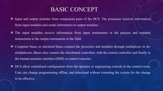
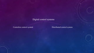
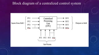
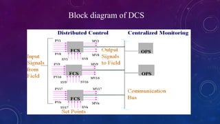
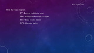
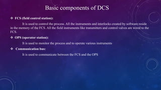
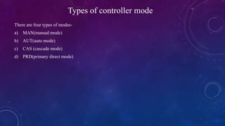

This document provides an overview of distributed control systems (DCS). It defines a DCS as a control system with distributed controllers located throughout the system to control subsystems, using proprietary communication protocols. The document describes the basic components of a DCS including field control stations, operator stations, and communication buses. It also outlines the different types of controller modes in a DCS.


![Engineer_post[1]](https://cdn.slidesharecdn.com/ss_thumbnails/7638a290-317f-44dc-af0b-484cd65aa062-160927061840-thumbnail.jpg?width=640&height=640&fit=bounds)