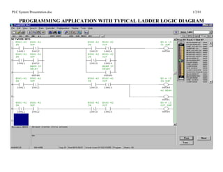
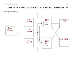
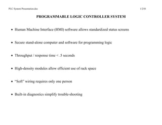
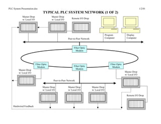
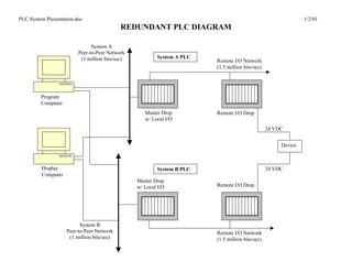
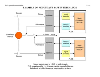
The document discusses the various uses of programmable logic controllers (PLCs) at Jefferson Lab, including for equipment status, process control, chemical processing, equipment interlocks, machine protection, smoke detection, gas monitoring, envelope monitoring, and personnel safety. PLCs are used for applications like chemical processing of niobium cavities, gas monitoring in experimental halls, machine protection for the Free Electron Laser, and beam envelope monitoring. The PLC system provides redundant and segmented control through independent PLCs, networking, and isolation. Rigorous testing and configuration control procedures are followed to ensure high reliability and availability of over 99.9996% during the lab's 10+ years of operation.

![PLC System Presentation.doc 1/2/01
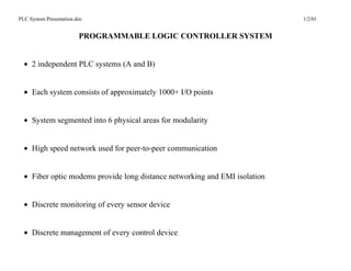
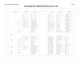
EXAMPLE OF THE SPEC FOR STATE LOGIC
Beam Permit =
[
Doors and Gates
&
/ Crash
&
Exchange Key IN
&
Sweep Complete
&
Radiation Monitor OK
&
High Voltage Ready
&
/ Laser Bypass
&
External Systems Ready
&
Chain Intact
&
( Beam Permit Key Switch Timer OR Beam Permit Mode )
]](https://image.slidesharecdn.com/plc-121202104157-phpapp02/85/PLC-27-320.jpg)
![PLC System Presentation.doc 1/2/01
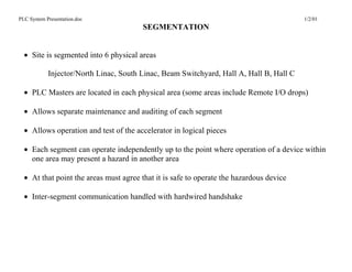
EXAMPLE OF THE SPEC FOR DEVICE LOGIC
RS(n) Operational =
[
(
(
Sweep Mode
&
RS(n) Set Interlock
)
OR
RS(n) Operational
)
&
/ RS(n) Crash
&
RS(n-1) Operational
]
Each programmer decides how to implement the logic in the context of the overall requirements for
the program
The two implementations are rarely immediately recognizable as being functionally equivalent](https://image.slidesharecdn.com/plc-121202104157-phpapp02/85/PLC-28-320.jpg)