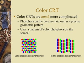
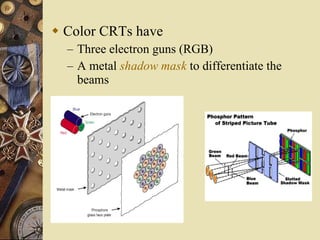
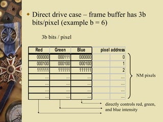
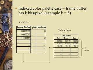
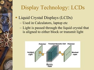
DISPLAY
HARDWARE
Cathode Ray Tubes
 Basic operation
 Refresh CRT
 Primary component –
          heated metal cathode
          control grid
          heating filament
 Intensity control – voltage on control grid
 Focusing System
            force the electron beam
  small spot of light
             Otherwise, electrons repel and
  spread
            Accomplished with electric or
  magnetic fields
 Deflection Plates  horizontal and vertical
 Spots on screen by transfer of CRT beam
  energy to phosphor
 Kinds of phosphor based on
             Color
             Persistence : time it takes the
  emitted light to decay one-tenth of original
  intensity

 Resolution

 Aspect Ratio
Raster Scan Displays
 Image created as Grid of Pixels – “Picture
  Elements” – Scan Conversion
 Picture definition is stored in a frame
  buffer memory or refresh buffer
     • one storage cell per pixel
 Example: assume a display of 16 x 16 pixels,
  each of which is either “on” or “off”
 The electron beam traces a path across the first
  row, then returns to starting side and moves
  across the second row, and so on
 The beam is turned on or off as
  it passes over a pixel that should
  be on or off
 Here, the beam is OFF for the
  entire first row, OFF during
  the retrace, and then ON for
  the two pixels that are ON
 Black and White (Bilevel) systems
       Bit Value 0: Beam turned ON
       Bit Value 1: Beam turned OFF
       Frame buffer : Bitmap
 For Color and intensity variations :
  multiple bits per pixel
       Frame buffer : Pixmap
 Refreshing : 60 – 80 frames per second
 Horizontal and Vertical Retrace
 Interlacing : with slower refreshing rates
Random Scan Display
 Also called as Vector or Stroke or
  Calligraphic Displays
 Draw a picture one line at a time
  – each image was expressed in the form of a
    series of {move-to, draw-to} commands
  – the beam could be moved to a specific x,y
    location while turned off, then turned-on, and
    a draw-to command would move the beam
    (while on) to a second x,y location – the result,
    a line drawn from the first location to the
    second
 Example:
  –   move to (a, b)
                                    (c, d)
  –   draw to (c, d)
  –   draw to (e, f)   (a, b)
  –   draw to (g, h)                           (e, f)
  –   draw to (a, b)
                                 (g, h)
  –   move to (i, j)
  –   draw to (k,l)     (i, j)               (k, l)
Note: Arrows just indicate the flow
 Refresh Display file contains the Line
  drawing commands
 For Line Drawing applications
 Higher resolution

 Problems with random-scan
  – as complexity of display grows, time to draw
    increases
  – if time between refreshes grows too long,
    display begins to flicker
Color CRT
 Color CRTs are much more complicated
   – Phosphors on the face are laid out in a precise
     geometric pattern
   – Uses a pattern of color phosphors on the
     screen:


Delta electron gun arrangement   In-line electron gun arrangement
 Color CRTs have
  – Three electron guns (RGB)
  – A metal shadow mask to differentiate the
   beams
 General case:
  – Simple color display has N x M pixels and
      each pixel is one of 8 = 23 colors
  –   color depth = k bits
  –   each pixel can be one of 2k colors
  –   if k = 3b, then there are 2b intensity levels for
      Red, Green, and Blue
  –   if k ≠ 3b, then typically a color indexing
      scheme is used
       • the value stored in the frame buffer is not used to
         directly control the drive intensity
       • frame buffer value is an index into a color palette
 Direct drive case – frame buffer has 3b
  bits/pixel (example b = 6)
      3b bits / pixel

   Red       Green      Blue      pixel address
    000000    000111     000000               0
    000100    000100     000100               1
    111111    111111     111111               2
        …          …         …               …       NM pixels
        …          …         …               …
        …          …         …               …
        …          …         …               …
                                    directly controls red, green,
                                    and blue intensity
 Indexed color palette case – frame buffer
  has k bits/pixel (example k = 8)

  k bits/pixel

 Frame Buffer pixel address
     00000000             0     3b bits / row
     00000010             1          Color Palette
     11111111             2   Red       Green        Blue
           …             …     000000     000111      000000
                               000100     000100      000100
           …             …     111111     111111      111111
           …             …         …          …           …    2k
           …             …         …          …           …    rows
                                   …          …           …
                                   …          …           …
Display Technology: LCDs
 Liquid Crystal Displays (LCDs)
  – Used in Calculators, laptop etc
  – Light is passed through the liquid crystal that
    is aligned to either block or transmit light
Display Technology: LCDs
 Liquid Crystal Displays (LCDs)
  – Used in Calculators, laptop etc
  – Light is passed through the liquid crystal that
    is aligned to either block or transmit light
Display Technology: Plasma
 Plasma display panels
  – Similar in principle to
    fluorescent light tubes
  – Small gas-filled capsules
    are excited by electric field,
    emits UV light
  – UV excites phosphor
  – Phosphor relaxes, emits
    some other color

Display Hardware

  • 1.
  • 2.
    Cathode Ray Tubes Basic operation  Refresh CRT  Primary component – heated metal cathode control grid heating filament
  • 3.
     Intensity control– voltage on control grid  Focusing System force the electron beam small spot of light  Otherwise, electrons repel and spread Accomplished with electric or magnetic fields  Deflection Plates  horizontal and vertical  Spots on screen by transfer of CRT beam energy to phosphor
  • 4.
     Kinds ofphosphor based on  Color  Persistence : time it takes the emitted light to decay one-tenth of original intensity  Resolution  Aspect Ratio
  • 5.
    Raster Scan Displays Image created as Grid of Pixels – “Picture Elements” – Scan Conversion  Picture definition is stored in a frame buffer memory or refresh buffer • one storage cell per pixel
  • 6.
     Example: assumea display of 16 x 16 pixels, each of which is either “on” or “off”  The electron beam traces a path across the first row, then returns to starting side and moves across the second row, and so on  The beam is turned on or off as it passes over a pixel that should be on or off  Here, the beam is OFF for the entire first row, OFF during the retrace, and then ON for the two pixels that are ON
  • 7.
     Black andWhite (Bilevel) systems  Bit Value 0: Beam turned ON  Bit Value 1: Beam turned OFF  Frame buffer : Bitmap  For Color and intensity variations : multiple bits per pixel  Frame buffer : Pixmap  Refreshing : 60 – 80 frames per second  Horizontal and Vertical Retrace  Interlacing : with slower refreshing rates
  • 8.
    Random Scan Display Also called as Vector or Stroke or Calligraphic Displays  Draw a picture one line at a time – each image was expressed in the form of a series of {move-to, draw-to} commands – the beam could be moved to a specific x,y location while turned off, then turned-on, and a draw-to command would move the beam (while on) to a second x,y location – the result, a line drawn from the first location to the second
  • 9.
     Example: – move to (a, b) (c, d) – draw to (c, d) – draw to (e, f) (a, b) – draw to (g, h) (e, f) – draw to (a, b) (g, h) – move to (i, j) – draw to (k,l) (i, j) (k, l) Note: Arrows just indicate the flow  Refresh Display file contains the Line drawing commands
  • 10.
     For LineDrawing applications  Higher resolution  Problems with random-scan – as complexity of display grows, time to draw increases – if time between refreshes grows too long, display begins to flicker
  • 11.
    Color CRT  ColorCRTs are much more complicated – Phosphors on the face are laid out in a precise geometric pattern – Uses a pattern of color phosphors on the screen: Delta electron gun arrangement In-line electron gun arrangement
  • 12.
     Color CRTshave – Three electron guns (RGB) – A metal shadow mask to differentiate the beams
  • 13.
     General case: – Simple color display has N x M pixels and each pixel is one of 8 = 23 colors – color depth = k bits – each pixel can be one of 2k colors – if k = 3b, then there are 2b intensity levels for Red, Green, and Blue – if k ≠ 3b, then typically a color indexing scheme is used • the value stored in the frame buffer is not used to directly control the drive intensity • frame buffer value is an index into a color palette
  • 14.
     Direct drivecase – frame buffer has 3b bits/pixel (example b = 6) 3b bits / pixel Red Green Blue pixel address 000000 000111 000000 0 000100 000100 000100 1 111111 111111 111111 2 … … … … NM pixels … … … … … … … … … … … … directly controls red, green, and blue intensity
  • 15.
     Indexed colorpalette case – frame buffer has k bits/pixel (example k = 8) k bits/pixel Frame Buffer pixel address 00000000 0 3b bits / row 00000010 1 Color Palette 11111111 2 Red Green Blue … … 000000 000111 000000 000100 000100 000100 … … 111111 111111 111111 … … … … … 2k … … … … … rows … … … … … …
  • 16.
    Display Technology: LCDs Liquid Crystal Displays (LCDs) – Used in Calculators, laptop etc – Light is passed through the liquid crystal that is aligned to either block or transmit light
  • 17.
    Display Technology: LCDs Liquid Crystal Displays (LCDs) – Used in Calculators, laptop etc – Light is passed through the liquid crystal that is aligned to either block or transmit light
  • 18.
    Display Technology: Plasma Plasma display panels – Similar in principle to fluorescent light tubes – Small gas-filled capsules are excited by electric field, emits UV light – UV excites phosphor – Phosphor relaxes, emits some other color