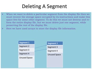
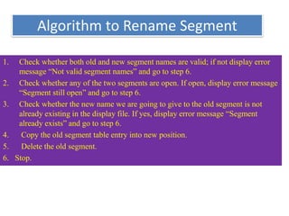
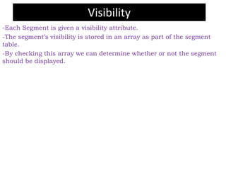
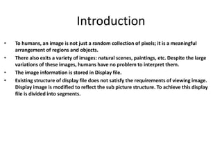
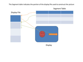
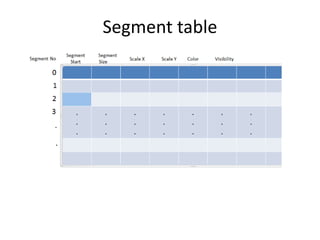
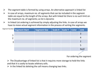
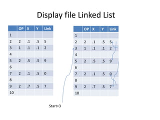
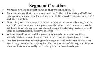
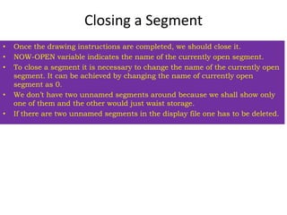
The document discusses image segmentation and the use of segments to structure image display. It describes how a display file can be divided into segments using a segment table. The segment table either uses arrays or linked lists to store segment information like start position, size, and attributes. Algorithms are provided for creating, closing, deleting, and renaming segments to dynamically manage the image display. Visibility attributes allow hiding or showing segments as needed.
Polygon is a figure having many slides. It may be represented as a number of line segments end to end to form a closed figure.
The line segments which form the boundary of the polygon are called edges or slides of the polygon.
The end of the side is called the polygon vertices.
Triangle is the most simple form of polygon having three side and three vertices.
The polygon may be of any shape.
a spline is a flexible strip used to produce a smooth curve through a designated set of points.
Polynomial sections are fitted so that the curve passes through each control point, Resulting curve is said to interpolate the set of control points.
a spline is a flexible strip used to produce a smooth curve through a designated set of points.
Polynomial sections are fitted so that the curve passes through each control point, Resulting curve is said to interpolate the set of control points.
GDE: Lab 1 – Traffic Light Pg. 1
Lab 1: Traffic Light
Setup
Start a new project. Save the scene. Review the submission steps at the bottom to ensure you save the scene
name correctly.
Additional References
Official Unity Tutorials: Unity has some fantastic learning tools to help newcomers become better
familiarized with the tool suite. I cannot recommend this enough.
Unity Scripting Reference: Unity's script reference is fantastic. If you want to know anything about a
particular component or function or class, they have it documented and easily accessible. It won't give
you all the answers, but without this, developing for Unity would become much, much more difficult.
Preparation
Make sure you complete Experiment 1 and 2 before attempting this lab.
Goal
The goal for this lab is to implement a simple traffic light that has a state machine driving its behavior. By the
end, you should have a visual representation of a traffic light with three spheres that represent the three lights.
Using time to determine when to transition, switch the lights from green, to yellow, to red and then back to
green. Additionally, input can be used to change the traffic light's behavior.
http://unity3d.com/learn
http://docs.unity3d.com/ScriptReference/
GDE: Lab 1 – Traffic Light Pg. 2
Instructions
Let's create the actual traffic light together. Here is the step-by-step construction process:
Create a Cube object
Rename the Cube object in the Hierarchy to TrafficLight
Create three Spheres. Rename them to Green Light, Yellow Light, and Red Light. Make the Traffic Light
object the parent of all of the Light objects by dragging all three spheres in the Hierarchy on top of the
TrafficLight object
GDE: Lab 1 – Traffic Light Pg. 3
Once all three spheres are children of the Traffic Light object, the only other thing left to add to the scene is
just a little bit of light. Add a directional light to the scene. The position of a directional light does not
matter. You can move it out of the way. If the light is too bright, you can lower the intensity in the inspector.
The scene should now roughly look like this. In scale mode, shape the cube until it looks like a traffic light.
Move the three light spheres such that they protrude through one side of the traffic light object. You'll
notice that the spheres have taken on the scale of the parent. It's important to remember that translation,
rotation and scale actions performed on the parent affect the children in the same way.
Use the scale tool to make the spheres look like a light again and position them accordingly
GDE: Lab 1 – Traffic Light Pg. 4
Once all three lights are in place, move the Main Camera object so that the Traffic Light object is in the
frame and you can see the light spheres
Scripting
Now you are ready to begin the programming portion of this lab! Select the Traffic Light object and add a
.
One of the most challenging tasks when developing an ADF application is achieving a proper layout. Both
stretching components and the ones that don't stretch can make a developer's life into a nightmare. In this
session you will learn best practices for creating complex layouts with ADF Faces. You will see how to use the
various ADF Layout components and build the layout that you need.
Partitioning is Dividing the large table and its indexes into smaller parts / partitions, so that maintenance operations can be applied on a partition-by-partition basis, rather than on the entire table.
z/OSMF Workflow Editor Lab - Try it out on your z/OSMF systemMarna Walle
This is a self-directed lab that you can use on your own z/OSMF V2.1 and higher system. All the samples are provided (in the Appendix) to create on your own system to use. Hints and tips from what Marna has discovered are shown.
Final project report on grocery store management system..pdfKamal Acharya
In today’s fast-changing business environment, it’s extremely important to be able to respond to client needs in the most effective and timely manner. If your customers wish to see your business online and have instant access to your products or services.
Online Grocery Store is an e-commerce website, which retails various grocery products. This project allows viewing various products available enables registered users to purchase desired products instantly using Paytm, UPI payment processor (Instant Pay) and also can place order by using Cash on Delivery (Pay Later) option. This project provides an easy access to Administrators and Managers to view orders placed using Pay Later and Instant Pay options.
In order to develop an e-commerce website, a number of Technologies must be studied and understood. These include multi-tiered architecture, server and client-side scripting techniques, implementation technologies, programming language (such as PHP, HTML, CSS, JavaScript) and MySQL relational databases. This is a project with the objective to develop a basic website where a consumer is provided with a shopping cart website and also to know about the technologies used to develop such a website.
This document will discuss each of the underlying technologies to create and implement an e- commerce website.
Industrial Training at Shahjalal Fertilizer Company Limited (SFCL)MdTanvirMahtab2
This presentation is about the working procedure of Shahjalal Fertilizer Company Limited (SFCL). A Govt. owned Company of Bangladesh Chemical Industries Corporation under Ministry of Industries.
Water scarcity is the lack of fresh water resources to meet the standard water demand. There are two type of water scarcity. One is physical. The other is economic water scarcity.
CFD Simulation of By-pass Flow in a HRSG module by R&R Consult.pptxR&R Consult
CFD analysis is incredibly effective at solving mysteries and improving the performance of complex systems!
Here's a great example: At a large natural gas-fired power plant, where they use waste heat to generate steam and energy, they were puzzled that their boiler wasn't producing as much steam as expected.
R&R and Tetra Engineering Group Inc. were asked to solve the issue with reduced steam production.
An inspection had shown that a significant amount of hot flue gas was bypassing the boiler tubes, where the heat was supposed to be transferred.
R&R Consult conducted a CFD analysis, which revealed that 6.3% of the flue gas was bypassing the boiler tubes without transferring heat. The analysis also showed that the flue gas was instead being directed along the sides of the boiler and between the modules that were supposed to capture the heat. This was the cause of the reduced performance.
Based on our results, Tetra Engineering installed covering plates to reduce the bypass flow. This improved the boiler's performance and increased electricity production.
It is always satisfying when we can help solve complex challenges like this. Do your systems also need a check-up or optimization? Give us a call!
Work done in cooperation with James Malloy and David Moelling from Tetra Engineering.
More examples of our work https://www.r-r-consult.dk/en/cases-en/
Welcome to WIPAC Monthly the magazine brought to you by the LinkedIn Group Water Industry Process Automation & Control.
In this month's edition, along with this month's industry news to celebrate the 13 years since the group was created we have articles including
A case study of the used of Advanced Process Control at the Wastewater Treatment works at Lleida in Spain
A look back on an article on smart wastewater networks in order to see how the industry has measured up in the interim around the adoption of Digital Transformation in the Water Industry.
Student information management system project report ii.pdfKamal Acharya
Our project explains about the student management. This project mainly explains the various actions related to student details. This project shows some ease in adding, editing and deleting the student details. It also provides a less time consuming process for viewing, adding, editing and deleting the marks of the students.
Hierarchical Digital Twin of a Naval Power SystemKerry Sado
A hierarchical digital twin of a Naval DC power system has been developed and experimentally verified. Similar to other state-of-the-art digital twins, this technology creates a digital replica of the physical system executed in real-time or faster, which can modify hardware controls. However, its advantage stems from distributing computational efforts by utilizing a hierarchical structure composed of lower-level digital twin blocks and a higher-level system digital twin. Each digital twin block is associated with a physical subsystem of the hardware and communicates with a singular system digital twin, which creates a system-level response. By extracting information from each level of the hierarchy, power system controls of the hardware were reconfigured autonomously. This hierarchical digital twin development offers several advantages over other digital twins, particularly in the field of naval power systems. The hierarchical structure allows for greater computational efficiency and scalability while the ability to autonomously reconfigure hardware controls offers increased flexibility and responsiveness. The hierarchical decomposition and models utilized were well aligned with the physical twin, as indicated by the maximum deviations between the developed digital twin hierarchy and the hardware.
2. Introduction
• To humans, an image is not just a random collection of pixels; it is a meaningful
arrangement of regions and objects.
• There also exits a variety of images: natural scenes, paintings, etc. Despite the large
variations of these images, humans have no problem to interpret them.
• The image information is stored in Display file.
• Existing structure of display file does not satisfy the requirements of viewing image.
Display image is modified to reflect the sub picture structure. To achieve this display
file is divided into segments.
3. The Segment table indicates the portion of the display file used to construct the picture
Display File
Segment Table
Display
5. The segment table is formed by using arrays. An alternative approach is linked list
In case of arrays, maximum no. of segments that can be included in the segment
table are equal to the length of the arrays. But with linked list there is no such limit on
the maximum no. of segments; as list is dynamic
In linked List ordering is achieved by simply adjusting the links. In case of arrays we
have to move actual segment information in the process of sorting the segments.
Segment Start Segment Size Scale X Scale Y Color Link
3
4
2
5
Null/
Segment Number
1
2
For ordering the segment
3
The Disadvantage of linked list is that it requires more storage to hold the links
and that it is costly to locate arbitrary cells.
In the linked list deleting the cell means changing two links.
6. Display file Linked List
OP X Y Link
1
2 2 .1 .5 5
3 1 .1 .1 2
4
5 2 .5 .5 9
6
7 2 .1 .5 0
8
9 2 .7 .5 7
10
Start=3
7. Segment Creation
We Must give the segment name so that we can identify it.
For example say that there is segment no. 3, then all following MOVE and
Line commands would belong to segment 3. We could then close segment 3
and open another.
First thing to create a segment is to check whether some other segment is
open. We can not open two segments at the same time because we would
not know to which segment we should assign the drawing instructions. If
there is segment open, we have an error
Next we should select valid segment name and check whether there
already exists a segment under this name. If so, we again have an error.
The first instruction belonging to this segment will be located at the next
free storage area in the display file. The current size of the segment is zero
since we have not actually entered any instructions into it yet.
8. CREATE_SEGMENT(SEGMENT-NAME)
Argument SEGMENT-NAME
Global NOW-OPEN the name of currently open segment
FREE the index of the next free display-file cell
SEGMENT-START, SEGMENT-SEZE,VISIBILITY
ANGLE, SCALE-X, SCALE-Y, TRANSLATE-X,TRANSLATE-Y
Constant NUMBER-OF-SEGMENTS
BEGIN
IF NOW-OPEN>0 THEN RETURN ERROR ‘SEGMENT STILL OPEN’;
IF SEGMENT-NAME < 1 OR SEGMENT-NAME > NUMBER-OF-SEGMENTS
THEN RETURN ERROR ‘INVALID SEGMENT NAME’;
IF SEGMENT-SIZE[SEGMENT-NAME]>0 THEN
RETURN ERROR ‘SEGMENT ALREADY EXISTS’;
SEGMENT-START[SEGMENT-NAME]<-FREE;
SEGMENT-SIZE[SEGMENT-NAME]<-0;
VISIBILITY[SEGMENT-NAME] <-VISIBILITY[0];
ANGLE[SEGMENT-NAME] <-ANGLE[0];
SCALE-X[SEGMENT-NAME]<-SCALE-X[0];
SCALE-Y[SEGMENT-NAME]<-SCALE-Y[0];
TRANSLATE-X[SEGMENT-NAME]<-TRANSLATE-X[0];
TRANSLATE-Y[SEGMENT-NAME]<-TRANSLATE-Y[0];
NOW-OPEN<-SEGMENT-NAME;
RETURN;
END;
9. Closing a Segment
• Once the drawing instructions are completed, we should close it.
• NOW-OPEN variable indicates the name of the currently open segment.
• To close a segment it is necessary to change the name of the currently open
segment. It can be achieved by changing the name of currently open
segment as 0.
• We don’t have two unnamed segments around because we shall show only
one of them and the other would just waist storage.
• If there are two unnamed segments in the display file one has to be deleted.
10. Algorithm to close Segment
Global NOW-OPEN the name of currently open segment
FREE the index of the next free display-file cell
SEGMENT-START, SEGMENT-SIZE start and size of
the segment
BEGIN
IF NOW-OPEN=0 THEN RETURN ERROR ‘NO
SEGMENT IS OPEN’;
DELETE-SEGMENT[0];
SEGMENT-START[0]<-FREE;
SEGMENT-SIZE[0]<-0;
NOW-OPEN<-0;
RETURN;
END;
11. Deleting A Segment
When we want to delete a particular segment from the display file then we
must recover the storage space occupied by its instructions and make this
space free for some other segment. To do this we must not destroy and re-
form the entire display file, but we must delete just one segment, while
preserving the rest of the display file.
Here we have used arrays to store the display file information.
Segment 1
Segment 2
Segment 3
Segment 4
Unused Space
Segment 1
Segment 3
Segment 4
Unused Space
12. Delete Algorithm
1. Read the name of the segment which is to be deleted.
2. Check whether the segment name is valid; if not display error “Segment
not valid” go to step 8
3. Check whether the segment is open, if yes, display error message “ Can’t
delete open segment” go to step 8.
4. Check whether the size of segment is greater than 0, if no, no processing
is required as segment contains no instructions.
5. Shift the display file elements which follow the segment which is to be
deleted by it’s size.
6. Recover the deleted space by resetting the index of the next free
instruction.
7. Adjust the starting positions of the shifted segments by subtracting the
size of the deleted segment from it.
8. Stop.
13. Renaming a Segment
• The display processor is continuously reading the display file and showing its
contents
• Suppose we wish to use this device to show an animated character moving on the
display.
• To display a new image in the sequence we have to delete the current segment and
re-create it with the altered character. The problem in this process is that during the
time after the first image is deleted and time before the second image is completely
entered, only a partially completed character is displayed on the screen.
• We avoid this problem by keeping the next image ready in the display file before
deleting the current segment.
• Segment which is to be deleted and segment which is to be replaced with must exist
in display file at the same time.
• We do this by building the new invisible image under some temporary segment
name. When it is completed, we can delete the original image, make the replacement
image visible, and rename the new segment to become the old segment to achieve
apparent motion.
• The idea of maintaining two images, one to show and one to build or alter, is called
double buffering.
14. Algorithm to Rename Segment
1. Check whether both old and new segment names are valid; if not display error
message “Not valid segment names” and go to step 6.
2. Check whether any of the two segments are open. If open, display error message
“Segment still open” and go to step 6.
3. Check whether the new name we are going to give to the old segment is not
already existing in the display file. If yes, display error message “Segment
already exists” and go to step 6.
4. Copy the old segment table entry into new position.
5. Delete the old segment.
6. Stop.
15. Visibility
-Each Segment is given a visibility attribute.
-The segment’s visibility is stored in an array as part of the segment
table.
-By checking this array we can determine whether or not the segment
should be displayed.