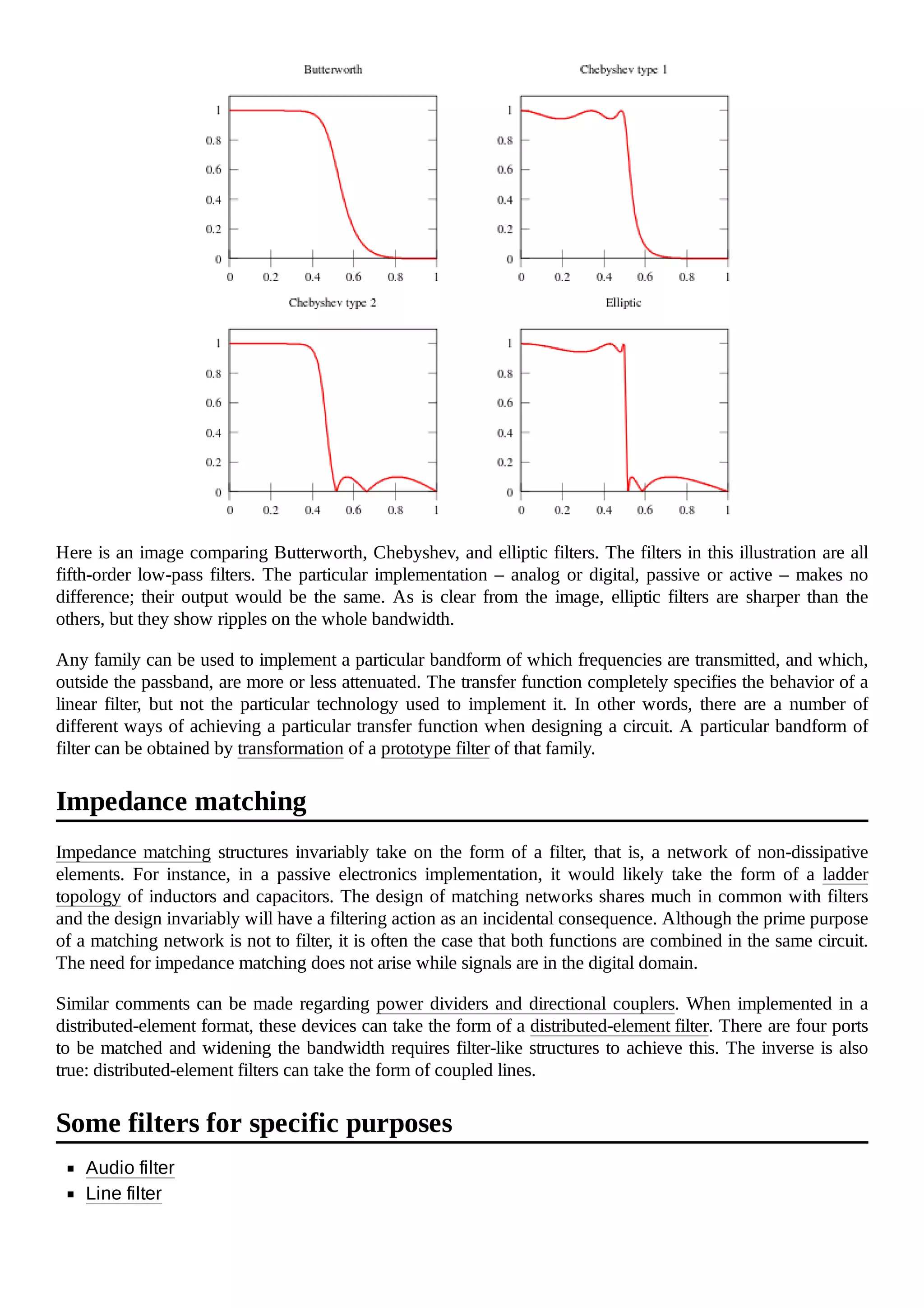
A filter in signal processing is a device or process that suppresses unwanted components from a signal, often removing specific frequency bands. Filters can be classified in various ways, including linear or non-linear, analog or digital, and passive or active, and they have important applications in electronics, telecommunications, and audio systems. The transfer function of a filter defines its behavior, and different families of filters, such as Butterworth, Chebyshev, and elliptic, offer various characteristics including response and cutoff behavior.
![Cutoff frequency is the frequency beyond which the filter will not pass signals. It is usually
measured at a specific attenuation such as 3 dB.
Roll-off is the rate at which attenuation increases beyond the cut-off frequency.
Transition band, the (usually narrow) band of frequencies between a passband and stopband.
Ripple is the variation of the filter's insertion loss in the passband.
The order of a filter is the degree of the approximating polynomial and in passive filters
corresponds to the number of elements required to build it. Increasing order increases roll-off
and brings the filter closer to the ideal response.
One important application of filters is in telecommunication. Many telecommunication systems use frequency-
division multiplexing, where the system designers divide a wide frequency band into many narrower
frequency bands called "slots" or "channels", and each stream of information is allocated one of those
channels. The people who design the filters at each transmitter and each receiver try to balance passing the
desired signal through as accurately as possible, keeping interference to and from other cooperating
transmitters and noise sources outside the system as low as possible, at reasonable cost.
Multilevel and multiphase digital modulation systems require filters that have flat phase delay—are linear
phase in the passband—to preserve pulse integrity in the time domain,[1] giving less intersymbol interference
than other kinds of filters.
On the other hand, analog audio systems using analog transmission can tolerate much larger ripples in phase
delay, and so designers of such systems often deliberately sacrifice linear phase to get filters that are better in
other ways—better stop-band rejection, lower passband amplitude ripple, lower cost, etc.
Filters can be built in a number of different technologies. The same transfer function can be realised in several
different ways, that is the mathematical properties of the filter are the same but the physical properties are quite
different. Often the components in different technologies are directly analogous to each other and fulfill the
same role in their respective filters. For instance, the resistors, inductors and capacitors of electronics
correspond respectively to dampers, masses and springs in mechanics. Likewise, there are corresponding
components in distributed-element filters.
Electronic filters were originally entirely passive consisting of resistance, inductance and
capacitance. Active technology makes design easier and opens up new possibilities in filter
specifications.
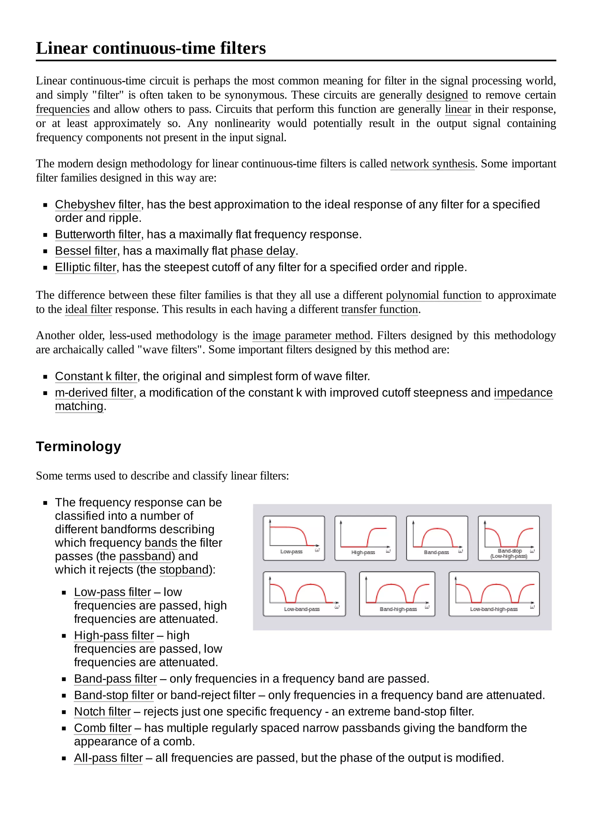
Digital filters operate on signals represented in digital form. The essence of a digital filter is that
it directly implements a mathematical algorithm, corresponding to the desired filter transfer
function, in its programming or microcode.
Mechanical filters are built out of mechanical components. In the vast majority of cases they are
used to process an electronic signal and transducers are provided to convert this to and from a
mechanical vibration. However, examples do exist of filters that have been designed for
operation entirely in the mechanical domain.
Distributed-element filters are constructed out of components made from small pieces of
transmission line or other distributed elements. There are structures in distributed-element
filters that directly correspond to the lumped elements of electronic filters, and others that are
unique to this class of technology.
Waveguide filters consist of waveguide components or components inserted in the waveguide.
Waveguides are a class of transmission line and many structures of distributed-element filters,
for instance the stub, can also be implemented in waveguides.
Technologies](https://image.slidesharecdn.com/filtersignalprocessing-210216022722/75/Filter-signal-processing-3-2048.jpg)
![to produce a direct analog implementation of a finite impulse response filter. This hybrid filtering technique is
also found in an analog sampled filter. SAW filters are limited to frequencies up to 3 GHz. The filters were
developed by Professor Ted Paige and others.[2]
BAW (bulk acoustic wave) filters are electromechanical devices. BAW filters can implement ladder or lattice
filters. BAW filters typically operate at frequencies from around 2 to around 16 GHz, and may be smaller or
thinner than equivalent SAW filters. Two main variants of BAW filters are making their way into devices: thin-
film bulk acoustic resonator or FBAR and solid mounted bulk acoustic resonators.
Another method of filtering, at microwave frequencies from 800 MHz to about 5 GHz, is to use a synthetic
single crystal yttrium iron garnet sphere made of a chemical combination of yttrium and iron (YIGF, or yttrium
iron garnet filter). The garnet sits on a strip of metal driven by a transistor, and a small loop antenna touches
the top of the sphere. An electromagnet changes the frequency that the garnet will pass. The advantage of this
method is that the garnet can be tuned over a very wide frequency by varying the strength of the magnetic
field.
For even higher frequencies and greater precision, the vibrations of atoms must be used. Atomic clocks use
caesium masers as ultra-high Q filters to stabilize their primary oscillators. Another method, used at high, fixed
frequencies with very weak radio signals, is to use a ruby maser tapped delay line.
The transfer function of a filter is most often defined in the domain of the complex frequencies. The back and
forth passage to/from this domain is operated by the Laplace transform and its inverse (therefore, here below,
the term "input signal" shall be understood as "the Laplace transform of" the time representation of the input
signal, and so on).
The transfer function of a filter is the ratio of the output signal to the input signal as a
function of the complex frequency :
with .
For filters that are constructed of discrete components (lumped elements):
Their transfer function will be the ratio of polynomials in , i.e. a rational function of . The order
of the transfer function will be the highest power of encountered in either the numerator or the
denominator polynomial.
The polynomials of the transfer function will all have real coefficients. Therefore, the poles and
zeroes of the transfer function will either be real or occur in complex-conjugate pairs.
BAW filters
Garnet filters
Atomic filters
The transfer function](https://image.slidesharecdn.com/filtersignalprocessing-210216022722/75/Filter-signal-processing-5-2048.jpg)