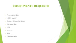
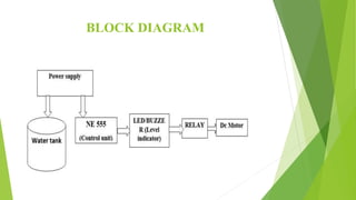
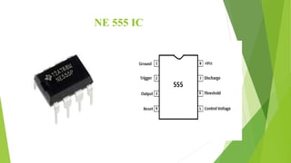
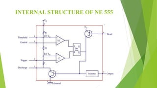
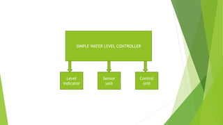
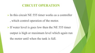
SIMPLE AUTOMATIC
WATER LEVAL
CONTROLLER
BY
T.SELVA LAKSHMI
FINAL YEAR ECE
DR.G.U.POPE COLLEGE OF ENGINEERING,
SAWYARPURAM
ABSTRACT
 People generally worry about the wastage of
water , when they switch ON the motor, but
forget to OFF them.
 Our idea may help them in saving water for
future with low cast.
CONTENTS
 Introduction
 Components required
 Block diagram
 Circuit diagram
 NE 555 IC
 NE 555 pin configuration
 Purpose of NE 555
 Level indicator
 Sensor unit
 Control unit
 Working principle
 Circuit operation
 Advantages
 Disadvantages
 Applications
INTRODUCTION
 Our project mainly consist of 555timer , 12V motor
,Relay and wires which acts as sensor.
 The wires are placed at the different levels of the tank.
 All these mentioned components take an active role in
switching ON and OFF of the motor.
COMPONENTS REQUIRED
 Power supply (12V)
 NE 555 timer IC
 Resistor (100 ohm-(2),1K ohm)
 D.C motor(12V)
 LED
 BUZZER
 Relay
 Connecting wires
BLOCK DIAGRAM
CIRCUIT DIAGRAM
NE 555 IC
INTERNAL STRUCTURE OF NE 555
PURPOSE OF NE 555
In this circuit the NE 555 works as a
comparator as well as a controller for
controlling the circuit operation.
SIMPLE WATER LEVEL CONTROLLER
Sensor
unit
Level
indicator
Control
unit
LEVEL INDICATOR
 The LED and BUZZER was used as a level indicator.
 When the water is in lower level , it was indicated with the help
of LED.
 When the water level is LOW the LED is glow.
 When the water level is goes high , then it was indicated with the
help of BUZZER.
 When the water is level is high then the BUZZER is switched
ON.
SENSOR UNIT
 In this circuit the connecting wires are used as a sensor, which
sense the level of water in the tank with the help of supply.
 In general the aluminum wire is used.
 The wires are connected on the tank and the power supply is
given through the wire to the water tank.
 The connected wires in LOW and HIGH position conduct the
electricity through water and sent these power to NE 555 for the
control of the motor operation.
CONTROL UNIT
 The NE 555 plays a main role in control unit .
 The NE 555 reciveces the signal from the sensor unit and generate the
output signal which was used to control the motor operation.
 If the water level in the tank is LOW then the output of the NE 555 is
HIGH , which switch ON the motor.
 If the water level in the tank is HIGH then the output of the NE 555 is
LOW , which switch OFF the motor.
WORKING PRINCIPLE
 This system mainly works on the principle that “ water
conducts electricity” .
 The four wires which are dipped into the tank will
indicate the different water levels.
 Based on the output of these wires ,the NE 555 timer
generate the signals which control the operation of the
motor.
CIRCUIT OPERATION
 When the 9V battery connected to the circuit , if
the water level of the tank low the NE 555 output
is high , which run the motor.
 If the water tank is full then NE 555 output is
low or even zero , which OFF the motor.
CIRCUIT OPERATION
 In this circuit NE 555 timer works as a controller
, which control operation of the motor.
 If water level is goes low then the NE 555 timer
output is high or maximum level which again run
the motor until when the tank is full.
ADVANTAGES
 Low maintenance.
 Compact and good design.
 Fully automatic.
 Saves water , energy.
 Increases pump life.
DISADVANTAGES
 This project may not be able to handle high power.
 The components used in this are sensitive and may
damage easily.
 We need to insert the wire in accordance with the
level of water.
APPLICATIONS
 It is used for all household purpose.
 It can be used in commercial centers.
 It will be very much useful to farmers.
 It can be used in all places to control water level.
CONCLUSION
This project involved designing simple
automatic water level controller with
low cast and using few components.
ANY QUESTIONS

Simple automatic water leval controller

  • 1.
    SIMPLE AUTOMATIC WATER LEVAL CONTROLLER BY T.SELVALAKSHMI FINAL YEAR ECE DR.G.U.POPE COLLEGE OF ENGINEERING, SAWYARPURAM
  • 2.
    ABSTRACT  People generallyworry about the wastage of water , when they switch ON the motor, but forget to OFF them.  Our idea may help them in saving water for future with low cast.
  • 3.
    CONTENTS  Introduction  Componentsrequired  Block diagram  Circuit diagram  NE 555 IC  NE 555 pin configuration  Purpose of NE 555  Level indicator  Sensor unit  Control unit  Working principle  Circuit operation  Advantages  Disadvantages  Applications
  • 4.
    INTRODUCTION  Our projectmainly consist of 555timer , 12V motor ,Relay and wires which acts as sensor.  The wires are placed at the different levels of the tank.  All these mentioned components take an active role in switching ON and OFF of the motor.
  • 5.
    COMPONENTS REQUIRED  Powersupply (12V)  NE 555 timer IC  Resistor (100 ohm-(2),1K ohm)  D.C motor(12V)  LED  BUZZER  Relay  Connecting wires
  • 6.
  • 7.
  • 8.
  • 9.
  • 10.
    PURPOSE OF NE555 In this circuit the NE 555 works as a comparator as well as a controller for controlling the circuit operation.
  • 11.
    SIMPLE WATER LEVELCONTROLLER Sensor unit Level indicator Control unit
  • 12.
    LEVEL INDICATOR  TheLED and BUZZER was used as a level indicator.  When the water is in lower level , it was indicated with the help of LED.  When the water level is LOW the LED is glow.  When the water level is goes high , then it was indicated with the help of BUZZER.  When the water is level is high then the BUZZER is switched ON.
  • 13.
    SENSOR UNIT  Inthis circuit the connecting wires are used as a sensor, which sense the level of water in the tank with the help of supply.  In general the aluminum wire is used.  The wires are connected on the tank and the power supply is given through the wire to the water tank.  The connected wires in LOW and HIGH position conduct the electricity through water and sent these power to NE 555 for the control of the motor operation.
  • 14.
    CONTROL UNIT  TheNE 555 plays a main role in control unit .  The NE 555 reciveces the signal from the sensor unit and generate the output signal which was used to control the motor operation.  If the water level in the tank is LOW then the output of the NE 555 is HIGH , which switch ON the motor.  If the water level in the tank is HIGH then the output of the NE 555 is LOW , which switch OFF the motor.
  • 15.
    WORKING PRINCIPLE  Thissystem mainly works on the principle that “ water conducts electricity” .  The four wires which are dipped into the tank will indicate the different water levels.  Based on the output of these wires ,the NE 555 timer generate the signals which control the operation of the motor.
  • 16.
    CIRCUIT OPERATION  Whenthe 9V battery connected to the circuit , if the water level of the tank low the NE 555 output is high , which run the motor.  If the water tank is full then NE 555 output is low or even zero , which OFF the motor.
  • 17.
    CIRCUIT OPERATION  Inthis circuit NE 555 timer works as a controller , which control operation of the motor.  If water level is goes low then the NE 555 timer output is high or maximum level which again run the motor until when the tank is full.
  • 18.
    ADVANTAGES  Low maintenance. Compact and good design.  Fully automatic.  Saves water , energy.  Increases pump life.
  • 19.
    DISADVANTAGES  This projectmay not be able to handle high power.  The components used in this are sensitive and may damage easily.  We need to insert the wire in accordance with the level of water.
  • 20.
    APPLICATIONS  It isused for all household purpose.  It can be used in commercial centers.  It will be very much useful to farmers.  It can be used in all places to control water level.
  • 21.
    CONCLUSION This project involveddesigning simple automatic water level controller with low cast and using few components.
  • 23.