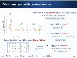
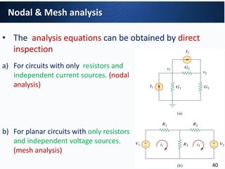
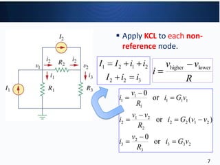
Circuit Theory I
Methods of Analysis
Assistant Professor Suna BOLAT
Eastern Mediterranean University
Department of Electric and Electronic Eng.
Ref2: Anant Agarwaland Jeffrey Lang, course materials for 6.002 Circuits and Electronics, Spring 2007.
MIT OpenCourseWare(http://ocw.mit.edu/), Massachusetts Institute of Technology1
The road so far...
• Method 1: Basic KVL, KCL method of Circuit analysis
• Method 2: Apply element combination rules
• Method 3: Nodal & Mesh analysis
– Particular application of KVL, KCL
2
Nodal & Mesh analysis
• Select reference node (ground) from which voltages are
measured.
• Label voltages of remaining nodes with respect to ground.
• These are the primary unknowns.
• Write KCL for all but the ground node, substituting device laws
and KVL.
• Solve for node voltages.
• Back solve for branch voltages and currents (i.e., the secondary
unknowns)
3
Nodal analysis
• Steps to Determine Node Voltages:
1. Select a node as the reference node. Assign voltage v1,
v2, …vn-1 to the remaining n-1 nodes. The voltages are
referenced with respect to the reference node.
2. Apply KCL to each of the n-1 non-reference nodes. Use
Ohm’s law to express the branch currents in terms of node
voltages.
3. Solve the resulting simultaneous equations to obtain the
unknown node voltages.
4
Nodal analysis
• Steps to Determine Node Voltages:
reference node
5
(a) common ground, (b) ground, (c) chassis.
Nodal Analysis
• Typical circuit for nodal analysis
voltages v1 and v2 are assigned with respect to the reference node
(i.e ground).
6
Reference Node
7
233
3
2
3
2122
2
21
2
111
1
1
1
or
0
)(or
or
0
vGi
R
v
i
vvGi
R
vv
i
vGi
R
v
i









1 2 1 2
2 2 3
I I i i
I i i
  
  R
vv
i lowerhigher 

 Apply KCL to each non-
reference node.
• Substituting element relations into KCL
8
3
2
2
21
2
2
21
1
1
21
R
v
R
vv
I
R
vv
R
v
II





232122
2121121
)(
)(
vGvvGI
vvGvGII





 












2
21
2
1
322
221
I
II
v
v
GGG
GGG
Example 3.1
• Calculate the node voltages in the circuit shown below.
9
• Calculate the node voltages in the circuit shown
below.
Example
10
Determine the voltages at nodes 1, 2 and 3.
Example 3.2
11
Reminder: Cramer’s rule
12
• Case 1: The voltage source is connected between a
nonreference node and the reference node: The
nonreference node voltage is equal to the magnitude of
voltage source and the number of unknown nonreference
nodes is reduced by one.
• Case 2: The voltage source is connected between two
nonreference nodes: a generalized node (supernode) is
formed.
Nodal Analysis with Voltage Sources
13
• A circuit with a supernode.
14
• A supernode is formed by enclosing a (dependent or
independent) voltage source connected between two
nonreference nodes and any elements connected in
parallel with it.
• The required two equations for regulating the two
nonreference node voltages are obtained by the KCL of the
supernode and the relationship of node voltages due to
the voltage source.
Supernode
15
• Find the node voltages of the circuit below.
i1 i2
1 2
1 2 1 2
1 2
2 7 0
2 7 0 5 2 20
2 4 2 4
i i
v v v v
v v
   
           
1 2 2v v  
1 2
1 2
2 20
2
v v
v v
  
  
1 1
2
22
3 22 = 7.33V
3
22 16
+2= = 5.33V
3 3
v v
v
     
    
Example
16
• Find the node voltages of the circuit below.
Example
17
• Apply KCL to the two supernodes.
At supernode 1-2:
Example (continued...)
18
• Apply KCL to the two supernodes.
At supernode 3-4:
Example (continued...)
19
• Apply KVL around the loops:
Loop1:
Loop2:
Loop3:
Example (continued...)
20
• You can use Matlab to solve large matrix equations:









































0
20
0
60
2103
0011
16524
2115
4
3
2
1
v
v
v
v
>> A=[5 1 -1 -2
4 2 -5 -16
1 -1 0 0
3 0 -1 -2];
>> B= [60 0 20 0]';
>> V=inv(A)*B
V =
26.6667
6.6667
173.3333
-46.6667
V67.46
V33.173
V67.6
V67.26
4
3
2
1




v
v
v
v
We now use MATLAB to solve the matrix Equation. The
Equation on the left can be written as
AV =B → V= B/A= A-1B
Matlab Code
Example (continued...)
21
1. Mesh analysis: another procedure for analyzing circuits,
applicable to planar circuits.
2. A Mesh is a loop which does not contain any other loops
within it.
3. Nodal analysis applies KCL to find voltages in a given circuit,
while Mesh Analysis applies KVL to calculate unknown
currents.
Mesh Analysis
22
• A circuit is planar if it can be drawn on a plane with no branches crossing
one another. Otherwise it is nonplanar.
• The circuit in (a) is planar, because the same circuit that is redrawn(b) has
no crossing branches.
Mesh Analysis
23
• A nonplanar circuit.
Mesh Analysis
24
• Steps to Determine Mesh Currents:
1. Assign mesh currents i1, i2, .., in to the n meshes.
2. Apply KVL to each of the n meshes. Use Ohm’s law to
express the voltages in terms of the mesh currents.
3. Solve the resulting n simultaneous equations to get
the mesh currents.
Mesh Analysis
25
• A circuit with two meshes.
Mesh Analysis
26
• A circuit with two meshes.
• Apply KVL to each mesh. For mesh 1,
• For mesh 2,
123131
213111
)(
0)(
ViRiRR
iiRiRV


223213
123222
)(
0)(
ViRRiR
iiRViR


Mesh Analysis
27
• Solve for the mesh currents.
• Use i for a mesh current and I for a branch current.
It’s evident from the circuit that:
















2
1
2
1
323
331
V
V
i
i
RRR
RRR
2132211 ,, iiIiIiI 
Mesh Analysis
28
• A circuit Find the branch currents I1, I2, and I3 using mesh
analysis.
Example 3.5
29
• For mesh 1,
• For mesh 2,
• We can find i1 and i2 by substitution method or Cramer’s
rule. Then,
123
010)(10515
21
211


ii
iii
12
010)(1046
21
1222


ii
iiii
2132211 ,, iiIiIiI 
Example 3.5
30
• Use mesh analysis to find the current Io in the circuit below.
Example 3.6
31
• Apply KVL to each mesh. For mesh 1,
• For mesh 2,
126511
0)(12)(1024
321
3121


iii
iiii
02195
0)(10)(424
321
12322


iii
iiiii
Example 3.6
32
• For mesh 3,
• In matrix from:
• we can calculate i1, i2 and i3 by Cramer’s rule, and find Io.
02
0)(4)(12)(4
,A,nodeAt
0)(4)(124
321
231321
210
23130




iii
iiiiii
iII
iiiiI




























0
0
12
211
2195
6511
3
2
1
i
i
i
Example 3.6
33
• Consider the following circuit with a current source.
Mesh analysis with current source
34
• Possibe cases of having a current source.
 Case 1
• Current source exist only in one mesh
mesh 2:
mesh 1:
• One mesh variable is reduced
 Case 2
• Current source exists between two meshes, a super-mesh is
obtained.
Mesh analysis with current source
35
• Possibe cases of having a current source.
• A supermesh is considerred when two meshes have a
(dependent/independent) current source in common.
Mesh analysis with current source
36
• Applying KVL in the supermesh below:
• KVL in the supermesh above:• Apply KCL at node 0 above:
Mesh analysis with current source
37
• Properties of a Supermesh
1. The current is not completely ignored
• provides the constraint equation necessary to solve for the
mesh current.
2. A supermesh has no current of its own.
3. Several current sources in adjacency form a bigger
supermesh.
4. A supermesh requires the application of both KVL and
KCL.
Mesh analysis with current source
38
• Apply KVL in the supermesh (mesh 1 + mesh 2 + mesh 3):
• Apply KVL in mesh 4:
• Apply KCL at node P:
• Apply KCL at node Q:










































0
5
5
0
3110
0011
5400
4631
4
3
2
1
i
i
i
i
• 4 equations for 4 variables. Using Cramer’s Rule
Mesh analysis with current source
39
• The analysis equations can be obtained by direct
inspection
a) For circuits with only resistors and
independent current sources. (nodal
analysis)
b) For planar circuits with only resistors
and independent voltage sources.
(mesh analysis)
Nodal & Mesh analysis
40
a) For circuits with only resistors and independent
current sources. (nodal analysis).
• The circuit has two nonreference nodes and the node
equations:
• In Matrix form:
• Consider the following example:
41
• In general, if a circuit with independent current sources has N
nonreference nodes, the node-voltage equations can be
written in terms of conductances as:
• G is called the conductance matrix, v is the output vector, and i is
the input vector. 42
b) For planar circuits with only resistors and independent
voltage sources. (mesh analysis)
• The circuit has two meshes and the mesh
equations :
• In Matrix form:
• Consider the following example:
43
• In general, if a circuit has N meshes, mesh-current equations
can be expressed in terms of resistances as:
• R is called the resistance matrix, i is the output vector, and v is the
input vector. 44
Write the node-voltage matrix equations in the following
circuit.
Example 3.8
45
625.1
1
1
2
1
8
1
,5.0
4
1
8
1
8
1
325.1
1
1
8
1
5
1
,3.0
10
1
5
1
4433
2211


GG
GG
125.0,1,0
125.0,125.0,0
1
1
1
,125.0
8
1
,2.0
0,2.0
5
1
434241
343231
242321
141312




GGG
GGG
GGG
GGG
• The circuit has 4 nonreference nodes, so the diagonal terms of G are:
• The off-diagonal terms of G are:
Example 3.8
46
• The input current vector i in amperes:
642,0,321,3 4321  iiii










































6
0
3
3
.62510.12510
0.125.500.1250
10.125.32510.2
000.2.30
4
3
2
1
v
v
v
v
• The node-voltage equations can be calculated by:
Example 3.8
47
Write the mesh-current equations in in the following circuit.
Example 3.9
48
6,0,6612
,6410,4
543
21


vvv
vv



















































6
0
6
6
4
43010
38010
00942
114012
00229
5
4
3
2
1
i
i
i
i
i
• The input voltage vector v in volts :
• The mesh-current equations are:
Example 3.9
49
• Both nodal and mesh analyses provide a systematic way of
analyzing a complex network.
• The choice of the better method is dictated by two factors.
 First factor: nature of the particular network.
 The key is to select the method that results in the
smaller number of equations.
 Second factor: information required.
Nodal vs mesh analysis
50
• Both nodal and mesh analysis provide a systematic way of
analyzing a complex network.
• The choice of the better method is dictated by two factors.
1. Nodal analysis: Apply KCL at the nonreference nodes.
(The circuit with fewer node equations)
2. A supernode: Voltage source between two nonreference
nodes.
3. Mesh analysis: Apply KVL for each mesh.
(The circuit with fewer mesh equations)
4. A supermesh: Current source between two meshes.
Summary
51
(a)An npn transistor,
(b) dc equivalent model.
Application: DC Transistor Circuits: BJT Circuit Models
52
For the BJT circuit in the figure =150 and VBE = 0.7 V. Find v0.
Example 3.13
53
• Use mesh analysis
or nodal analysis
Example 3.13
54

Circuit theory 1-c3-analysis methods

  • 1.
    Circuit Theory I Methodsof Analysis Assistant Professor Suna BOLAT Eastern Mediterranean University Department of Electric and Electronic Eng. Ref2: Anant Agarwaland Jeffrey Lang, course materials for 6.002 Circuits and Electronics, Spring 2007. MIT OpenCourseWare(http://ocw.mit.edu/), Massachusetts Institute of Technology1
  • 2.
    The road sofar... • Method 1: Basic KVL, KCL method of Circuit analysis • Method 2: Apply element combination rules • Method 3: Nodal & Mesh analysis – Particular application of KVL, KCL 2
  • 3.
    Nodal & Meshanalysis • Select reference node (ground) from which voltages are measured. • Label voltages of remaining nodes with respect to ground. • These are the primary unknowns. • Write KCL for all but the ground node, substituting device laws and KVL. • Solve for node voltages. • Back solve for branch voltages and currents (i.e., the secondary unknowns) 3
  • 4.
    Nodal analysis • Stepsto Determine Node Voltages: 1. Select a node as the reference node. Assign voltage v1, v2, …vn-1 to the remaining n-1 nodes. The voltages are referenced with respect to the reference node. 2. Apply KCL to each of the n-1 non-reference nodes. Use Ohm’s law to express the branch currents in terms of node voltages. 3. Solve the resulting simultaneous equations to obtain the unknown node voltages. 4
  • 5.
    Nodal analysis • Stepsto Determine Node Voltages: reference node 5 (a) common ground, (b) ground, (c) chassis.
  • 6.
    Nodal Analysis • Typicalcircuit for nodal analysis voltages v1 and v2 are assigned with respect to the reference node (i.e ground). 6 Reference Node
  • 7.
    7 233 3 2 3 2122 2 21 2 111 1 1 1 or 0 )(or or 0 vGi R v i vvGi R vv i vGi R v i          1 2 12 2 2 3 I I i i I i i      R vv i lowerhigher    Apply KCL to each non- reference node.
  • 8.
    • Substituting elementrelations into KCL 8 3 2 2 21 2 2 21 1 1 21 R v R vv I R vv R v II      232122 2121121 )( )( vGvvGI vvGvGII                    2 21 2 1 322 221 I II v v GGG GGG
  • 9.
    Example 3.1 • Calculatethe node voltages in the circuit shown below. 9
  • 10.
    • Calculate thenode voltages in the circuit shown below. Example 10
  • 11.
    Determine the voltagesat nodes 1, 2 and 3. Example 3.2 11
  • 12.
  • 13.
    • Case 1:The voltage source is connected between a nonreference node and the reference node: The nonreference node voltage is equal to the magnitude of voltage source and the number of unknown nonreference nodes is reduced by one. • Case 2: The voltage source is connected between two nonreference nodes: a generalized node (supernode) is formed. Nodal Analysis with Voltage Sources 13
  • 14.
    • A circuitwith a supernode. 14
  • 15.
    • A supernodeis formed by enclosing a (dependent or independent) voltage source connected between two nonreference nodes and any elements connected in parallel with it. • The required two equations for regulating the two nonreference node voltages are obtained by the KCL of the supernode and the relationship of node voltages due to the voltage source. Supernode 15
  • 16.
    • Find thenode voltages of the circuit below. i1 i2 1 2 1 2 1 2 1 2 2 7 0 2 7 0 5 2 20 2 4 2 4 i i v v v v v v                 1 2 2v v   1 2 1 2 2 20 2 v v v v       1 1 2 22 3 22 = 7.33V 3 22 16 +2= = 5.33V 3 3 v v v            Example 16
  • 17.
    • Find thenode voltages of the circuit below. Example 17
  • 18.
    • Apply KCLto the two supernodes. At supernode 1-2: Example (continued...) 18
  • 19.
    • Apply KCLto the two supernodes. At supernode 3-4: Example (continued...) 19
  • 20.
    • Apply KVLaround the loops: Loop1: Loop2: Loop3: Example (continued...) 20
  • 21.
    • You canuse Matlab to solve large matrix equations:                                          0 20 0 60 2103 0011 16524 2115 4 3 2 1 v v v v >> A=[5 1 -1 -2 4 2 -5 -16 1 -1 0 0 3 0 -1 -2]; >> B= [60 0 20 0]'; >> V=inv(A)*B V = 26.6667 6.6667 173.3333 -46.6667 V67.46 V33.173 V67.6 V67.26 4 3 2 1     v v v v We now use MATLAB to solve the matrix Equation. The Equation on the left can be written as AV =B → V= B/A= A-1B Matlab Code Example (continued...) 21
  • 22.
    1. Mesh analysis:another procedure for analyzing circuits, applicable to planar circuits. 2. A Mesh is a loop which does not contain any other loops within it. 3. Nodal analysis applies KCL to find voltages in a given circuit, while Mesh Analysis applies KVL to calculate unknown currents. Mesh Analysis 22
  • 23.
    • A circuitis planar if it can be drawn on a plane with no branches crossing one another. Otherwise it is nonplanar. • The circuit in (a) is planar, because the same circuit that is redrawn(b) has no crossing branches. Mesh Analysis 23
  • 24.
    • A nonplanarcircuit. Mesh Analysis 24
  • 25.
    • Steps toDetermine Mesh Currents: 1. Assign mesh currents i1, i2, .., in to the n meshes. 2. Apply KVL to each of the n meshes. Use Ohm’s law to express the voltages in terms of the mesh currents. 3. Solve the resulting n simultaneous equations to get the mesh currents. Mesh Analysis 25
  • 26.
    • A circuitwith two meshes. Mesh Analysis 26
  • 27.
    • A circuitwith two meshes. • Apply KVL to each mesh. For mesh 1, • For mesh 2, 123131 213111 )( 0)( ViRiRR iiRiRV   223213 123222 )( 0)( ViRRiR iiRViR   Mesh Analysis 27
  • 28.
    • Solve forthe mesh currents. • Use i for a mesh current and I for a branch current. It’s evident from the circuit that:                 2 1 2 1 323 331 V V i i RRR RRR 2132211 ,, iiIiIiI  Mesh Analysis 28
  • 29.
    • A circuitFind the branch currents I1, I2, and I3 using mesh analysis. Example 3.5 29
  • 30.
    • For mesh1, • For mesh 2, • We can find i1 and i2 by substitution method or Cramer’s rule. Then, 123 010)(10515 21 211   ii iii 12 010)(1046 21 1222   ii iiii 2132211 ,, iiIiIiI  Example 3.5 30
  • 31.
    • Use meshanalysis to find the current Io in the circuit below. Example 3.6 31
  • 32.
    • Apply KVLto each mesh. For mesh 1, • For mesh 2, 126511 0)(12)(1024 321 3121   iii iiii 02195 0)(10)(424 321 12322   iii iiiii Example 3.6 32
  • 33.
    • For mesh3, • In matrix from: • we can calculate i1, i2 and i3 by Cramer’s rule, and find Io. 02 0)(4)(12)(4 ,A,nodeAt 0)(4)(124 321 231321 210 23130     iii iiiiii iII iiiiI                             0 0 12 211 2195 6511 3 2 1 i i i Example 3.6 33
  • 34.
    • Consider thefollowing circuit with a current source. Mesh analysis with current source 34
  • 35.
    • Possibe casesof having a current source.  Case 1 • Current source exist only in one mesh mesh 2: mesh 1: • One mesh variable is reduced  Case 2 • Current source exists between two meshes, a super-mesh is obtained. Mesh analysis with current source 35
  • 36.
    • Possibe casesof having a current source. • A supermesh is considerred when two meshes have a (dependent/independent) current source in common. Mesh analysis with current source 36
  • 37.
    • Applying KVLin the supermesh below: • KVL in the supermesh above:• Apply KCL at node 0 above: Mesh analysis with current source 37
  • 38.
    • Properties ofa Supermesh 1. The current is not completely ignored • provides the constraint equation necessary to solve for the mesh current. 2. A supermesh has no current of its own. 3. Several current sources in adjacency form a bigger supermesh. 4. A supermesh requires the application of both KVL and KCL. Mesh analysis with current source 38
  • 39.
    • Apply KVLin the supermesh (mesh 1 + mesh 2 + mesh 3): • Apply KVL in mesh 4: • Apply KCL at node P: • Apply KCL at node Q:                                           0 5 5 0 3110 0011 5400 4631 4 3 2 1 i i i i • 4 equations for 4 variables. Using Cramer’s Rule Mesh analysis with current source 39
  • 40.
    • The analysisequations can be obtained by direct inspection a) For circuits with only resistors and independent current sources. (nodal analysis) b) For planar circuits with only resistors and independent voltage sources. (mesh analysis) Nodal & Mesh analysis 40
  • 41.
    a) For circuitswith only resistors and independent current sources. (nodal analysis). • The circuit has two nonreference nodes and the node equations: • In Matrix form: • Consider the following example: 41
  • 42.
    • In general,if a circuit with independent current sources has N nonreference nodes, the node-voltage equations can be written in terms of conductances as: • G is called the conductance matrix, v is the output vector, and i is the input vector. 42
  • 43.
    b) For planarcircuits with only resistors and independent voltage sources. (mesh analysis) • The circuit has two meshes and the mesh equations : • In Matrix form: • Consider the following example: 43
  • 44.
    • In general,if a circuit has N meshes, mesh-current equations can be expressed in terms of resistances as: • R is called the resistance matrix, i is the output vector, and v is the input vector. 44
  • 45.
    Write the node-voltagematrix equations in the following circuit. Example 3.8 45
  • 46.
  • 47.
    • The inputcurrent vector i in amperes: 642,0,321,3 4321  iiii                                           6 0 3 3 .62510.12510 0.125.500.1250 10.125.32510.2 000.2.30 4 3 2 1 v v v v • The node-voltage equations can be calculated by: Example 3.8 47
  • 48.
    Write the mesh-currentequations in in the following circuit. Example 3.9 48
  • 49.
  • 50.
    • Both nodaland mesh analyses provide a systematic way of analyzing a complex network. • The choice of the better method is dictated by two factors.  First factor: nature of the particular network.  The key is to select the method that results in the smaller number of equations.  Second factor: information required. Nodal vs mesh analysis 50
  • 51.
    • Both nodaland mesh analysis provide a systematic way of analyzing a complex network. • The choice of the better method is dictated by two factors. 1. Nodal analysis: Apply KCL at the nonreference nodes. (The circuit with fewer node equations) 2. A supernode: Voltage source between two nonreference nodes. 3. Mesh analysis: Apply KVL for each mesh. (The circuit with fewer mesh equations) 4. A supermesh: Current source between two meshes. Summary 51
  • 52.
    (a)An npn transistor, (b)dc equivalent model. Application: DC Transistor Circuits: BJT Circuit Models 52
  • 53.
    For the BJTcircuit in the figure =150 and VBE = 0.7 V. Find v0. Example 3.13 53
  • 54.
    • Use meshanalysis or nodal analysis Example 3.13 54