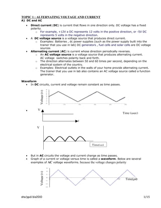
1) AC voltage periodically reverses direction, switching polarity back and forth 50-60 times per second, whereas DC voltage flows in one direction only.
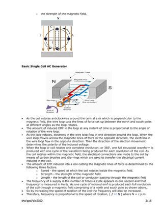
2) Any change in a coil's magnetic environment, such as moving it within a magnetic field, induces an electromotive force (EMF) in the coil based on Faraday's law of induction.
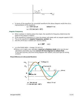
3) In a basic single coil AC generator, the coil's rotation within a magnetic field produces a sinusoidal alternating current, with the instantaneous voltage determined by the coil's position and the maximum induced voltage.
Magnetic Effects Of Current Class 12 Part-2Self-employed
The document discusses various topics related to the magnetic effects of electric current:
1. It defines Lorentz force and Fleming's left hand rule for determining the direction of force on a current-carrying conductor in a magnetic field.
2. It describes the forces experienced by moving charges and current-carrying conductors in both uniform electric and magnetic fields.
3. It provides the definition of the ampere based on the forces experienced between two parallel current-carrying conductors.
The document summarizes key concepts about electromagnetic induction, including:
- Electromagnetic induction occurs when a magnet moves in and out of a solenoid, cutting the magnetic flux and inducing a current in the wire coil.
- Faraday's law and Lenz's law govern the direction and magnitude of induced currents.
- An AC generator uses the principle of electromagnetic induction to generate an alternating current through the rotation of a coil within a magnetic field.
- Transformers are used to change the voltage of an AC supply through electromagnetic induction between a primary and secondary coil.
1. The document discusses various topics related to magnetic fields including the magnetic field produced by electric currents, magnetic field lines, the magnetic field of the Earth, and the forces experienced by moving charges and current-carrying conductors in magnetic fields.
2. Key concepts covered include the Biot-Savart law for calculating magnetic fields, the right hand rule for determining magnetic field direction, the motion of charged particles in uniform magnetic fields, and applications such as mass spectrometers and the aurora borealis.
3. Measurement techniques for magnetic fields including using a current balance, search coil, and Hall probe are also summarized.
Alternating Current -12 isc 2017 ( investigatory Project) Student
In this file, we will study about the various types of ac circuits, how they work,their phasor diagrams,types of periodic form,analytical method and graphical method to find average value of alternating current.
This document summarizes key concepts about transformers:
1) Transformers transfer electrical energy from one voltage level to another through magnetic coupling between primary and secondary coils. They do not directly convert electrical to mechanical energy.
2) An ideal transformer transfers power without losses, but real transformers have resistive losses in their coils and core that reduce efficiency.
3) The voltage and current ratios between primary and secondary coils are determined by their relative turn ratios; this relationship allows impedances to be transferred between sides.
This document discusses standing waves that occur on transmission lines terminated in an open or short circuit. When a transmission line is terminated in an open or short circuit, the voltage and current waves traveling along the line are fully reflected. The interference between the incident and reflected waves creates a standing wave pattern along the line, with maxima and minima of voltage and current repeating every half wavelength. Key characteristics are described, such as impedance being highest at open/short ends and lowest at quarter wavelength points.
The document discusses magnetic fields, flux, permeability, inductance, electromagnetic induction, Lenz's law, and the working principles of DC generators and motors. It describes the main components of DC machines including the field system, armature, commutator, and brushes. Equations for emf generation in DC generators are presented. The types of DC generator excitation including separately excited, self-excited, series, shunt, and compound wound generators are defined. The characteristics curves for DC machines such as no-load saturation, internal, and external characteristics are also summarized.
Ac waveform and ac circuit theory of sinusoidsSoham Gajjar
- Direct current (DC) flows in one direction, while alternating current (AC) varies in both magnitude and direction over time, typically following a sinusoidal waveform.
- The key characteristics of an AC waveform are its period, frequency, and amplitude. The period is the time it takes to complete one cycle, frequency is the number of cycles per second, and amplitude is the maximum voltage or current value.
- Common AC waveforms include sinusoidal, square, and triangular waves. The domestic power supply typically uses a 50Hz or 60Hz sinusoidal waveform.
- Direct current (DC) flows in one direction, while alternating current (AC) varies in both magnitude and direction over time.
- An AC waveform is generated by rotating a coil within a magnetic field, inducing an electromagnetic force (EMF) that changes with the coil's position.
- The amplitude, frequency, and period define the characteristics of an AC waveform. The root mean square (RMS) and average values are also important metrics.
This document discusses fundamentals of alternating current (AC), including:
- AC voltage is generated as sinusoidal waves by power plants and used worldwide.
- Key definitions for AC waves include waveform, instantaneous value, peak amplitude, peak-to-peak value, cycle, period, and frequency.
- The basic mathematical form for a sinusoidal AC waveform is y = A sin(ωt), where A is the amplitude and ωt represents angular displacement over time.
- Root mean square (RMS) value represents the effective or heating value of AC and is calculated as the square root of the mean of the squares of the instantaneous values over one cycle.
- Average value of a symmetrical AC waveform is
A few basics about magnetism and Alternating currents.
Students of APJ Abdul Kalam Technological University (KTU) may find this helpful for their second module for the subject EE100 BASICS OF ELECTRICAL ENGINEERING.
1. Electric currents flowing in wires produce magnetic fields around the wires. The direction of the magnetic field can be determined using the right-hand grip rule.
2. A wire carrying a current experiences a force when placed in a magnetic field. The direction of this force can be determined using Fleming's left-hand rule. Charged particles also experience a force in a magnetic field.
3. Parallel wires with currents in the same direction attract, while parallel wires with currents in opposite directions repel. This is due to the interaction of the magnetic fields produced by each current.
1) Alternating current (AC) refers to sinusoidal voltage and current waveforms. AC can be generated from sources like AC generators, wind turbines, hydroelectric power plants, and solar panels.
2) Key characteristics of AC waveforms include instantaneous value, peak amplitude, peak value, peak-to-peak value, period, frequency, phase, and whether they are periodic.
3) Sinusoidal waves can be expressed as v = Vm sin(ωt+θ), where Vm is the peak amplitude, ω is the angular frequency, t is time, and θ is the phase. The phase relationship between two sinusoidal waves indicates whether one leads or lags the other.
1. Alternating current (AC) electricity alternates direction periodically compared to direct current (DC) which flows in one direction. AC is generated by AC generators at frequencies like 50-60 Hz.
2. The root mean square (rms) value is used to quantify AC voltage and current as it represents the equivalent steady DC power. Rms current and voltage are defined using formulas involving averaging the square of the instantaneous values.
3. In AC circuits, elements have both resistance and reactance properties. Resistance is opposition to current from resistance. Reactance is opposition from inductance or capacitance. Capacitive and inductive reactance are defined using frequency and element values. Impedance combines resistance and
This document defines electricity and electric current. It explains that electric current is the flow of electric charge and is measured in Amperes. It also discusses different types of current sources like cells, generators, thermo-couples and solar cells. The document then covers several effects of electric current including heating, chemical, and magnetic effects. It explains electromagnetism and how electric currents produce magnetic fields based on experiments by Hans Oersted.
This document provides an overview of a lecture on single phase AC circuits. It defines key terms related to alternating quantities like amplitude, time period, frequency, and phasor representation. It also explains AC circuits with pure resistance, inductance and capacitance. The document is presented by a professor from the International Institute of Information Technology in Pune, India. It provides background on the institute, which was established to promote innovation and quality education.
1) The Earth behaves like a giant bar magnet with magnetic north and south poles. Its magnetic field is generated by electrical currents in the liquid outer core due to convection of iron and nickel.
2) The magnetic poles do not align with the geographic poles, as the magnetic axis is tilted about 11 degrees from the Earth's rotational axis.
3) The dynamo effect in the outer core sustains the Earth's magnetic field through convection-driven electrical currents that act like a self-exciting dynamo.
In statically induced emf, conductor is stationary with respect to the magnetic field.
Transformer is an example of statically induced emf. Here the windings are stationary,magnetic field is moving around the conductor and produces the emf.
1) Magnets have north and south poles that attract or repel each other depending on their orientation. They generate magnetic fields around them represented by field lines.
2) Charged particles experience a magnetic force when moving through a magnetic field that is perpendicular to both the field and velocity directions. The right hand rule determines the force direction.
3) Current-carrying wires also experience a magnetic force when placed in an external magnetic field due to their internal magnetic field generated by the current.
Magnetic Effects Of Current Class 12 Part-1Self-employed
The document discusses the magnetic effects of electric current, including:
1) Oersted's experiment showing a current-carrying wire deflects a magnetic needle.
2) Rules for determining the direction of magnetic fields, including Ampere's swimming rule and Maxwell's corkscrew rule.
3) Biot-Savart's law, which describes the magnetic field created by a current-carrying element as proportional to the current and inversely proportional to the distance.
The document discusses AC circuits and phasor diagrams. It introduces AC sources and defines RMS values. It describes how resistors, capacitors, and inductors behave in AC circuits, with the voltage across a resistor being in phase with current, the voltage across a capacitor lagging current, and the voltage across an inductor leading current. Kirchoff's loop equation is presented and phasors are introduced to represent instantaneous voltages, allowing the maximum voltages to be calculated even when they occur at different times. Example phasor diagrams are shown graphically.
1. The document describes magnetic circuits and electromagnetic induction. It defines key terms related to magnetism such as magnetic flux, magnetic field, hysteresis, reluctance, and permeability.
2. The document explains different types of magnetic circuits including simple, composite, and parallel circuits. It also discusses magnetic leakage.
3. Electromagnetic induction is described according to Faraday's law and Lenz's law. Dynamically and statically induced emfs are defined and examples of each are provided.
Transmission lines connect generators to loads and include parallel wires, coaxial cable, and optical fiber. They can experience effects like delay, dispersion, and attenuation. Different transmission modes include TEM where electric and magnetic fields are orthogonal to the direction of propagation. The transmission line is modeled as a distributed circuit with inductance and capacitance. This leads to transmission line equations that can be solved as wave equations. The characteristic impedance of the line determines how waves propagate on the line, with standing wave patterns forming for mismatched loads. The input impedance of the line depends on the load impedance and distance along the line.
AC circuits usually contain inductance or capacitance which cause reactance. Reactance is resistance to current flow due to these components and is measured in ohms. There are two types of reactance - inductive reactance XL and capacitive reactance XC. Phasor diagrams can represent alternating quantities, with the phase angle between voltage and current indicating whether a circuit is resistive, capacitive, or inductive.
1) The document discusses the generation of alternating current using a single-turn alternator with a rotating coil within a magnetic field.
2) As the coil rotates, an alternating voltage is induced based on Faraday's law of electromagnetic induction. The magnitude of the induced voltage depends on the angle of rotation and reaches its maximum when the coil is perpendicular to the magnetic field lines.
3) The instantaneous induced voltage can be expressed as a sinusoidal function of the angle of rotation, with the maximum voltage achieved at 90° of rotation. This generates an alternating current through a load that also follows a sinusoidal pattern.
When the current in one coil of a transformer changes, it induces a magnetic field that causes an emf in the other coil, known as mutual induction. Transformers use this principle of mutual induction to step up or step down voltages using a primary coil with fewer turns of thick wire connected to the power source, and a secondary coil with more turns of thin wire to deliver the output voltage. The relationship between the voltages and number of turns in each coil can be expressed mathematically.
This document discusses alternating voltages and currents in electrical circuits. It begins by differentiating between alternating current (AC) and direct current (DC), and explaining why AC is commonly used over DC for power transmission and distribution. Some key points covered include:
- AC voltage and current waveforms oscillate back and forth rather than flowing in one constant direction.
- AC can be increased or decreased in voltage using transformers, making it more economical for transmission over long distances.
- Common sources of AC include rotating electrical machines like AC generators and electronic oscillators.
- Sinusoidal waveforms are produced by rotating coils in magnetic fields based on Faraday's and Lenz's laws. Equations are developed to
Electrical energy is created by the movement of electrons through a circuit. A circuit can be open or closed, with a closed circuit allowing electrons to flow freely and an open circuit preventing flow. Materials that allow or prevent electron flow are conductors and insulators respectively, with common examples like copper and plastic provided.
This document discusses different types of circuits including closed and open circuits, circuit diagrams, common circuit symbols, series and parallel circuits, and short circuits. It explains that closed circuits allow electricity to flow while open circuits do not. Series circuits have a single path for current to flow and if any part fails the entire circuit fails, while parallel circuits have multiple independent paths so if one fails the others still work. Short circuits bypass devices and drain batteries faster while risking fires from overheating wires.
This document provides an overview of Tenaga Nasional Berhad (TNB), Malaysia's largest electric utility company. It outlines TNB's vision, mission, core values, business divisions, core and non-core businesses, generation and transmission assets, and organization structure in 3 paragraphs or less.
TNB is the largest electricity utility company in Malaysia, providing generation, transmission, and distribution of electricity across Peninsular Malaysia, Sabah, and Labuan. It has over 33,500 employees serving over 8.3 million customers. TNB traces its origins back to 1949 when it was established as the Central Electricity Board to power Malaysia's national development through reliable and efficient electricity provision.
This document contains 13 solved problems related to rectifier circuits using diodes. The problems calculate various electrical characteristics of half-wave, full-wave, and bridge rectifier circuits, including DC and AC voltages and currents, power delivered to loads, ripple factor, transformer specifications, and diode voltage ratings. Example calculations are shown for circuits using a single diode, full-wave rectifiers, and full-wave rectifiers with LC filter components.
This document discusses short circuits, open circuits, and transformer tests. It explains that a short circuit allows current along an unintended path with little resistance, while an open circuit lacks a complete path for current flow. Transformer tests include open circuit and short circuit tests. The open circuit test determines core losses and shunt branch parameters, while the short circuit test determines copper losses and approximate circuit parameters. Instruments are connected and measurements recorded to evaluate losses and parameters from the tests.
This document discusses the differences between direct current (DC) and alternating current (AC). DC such as from batteries has a constant flow from negative to positive terminals at a typical voltage of 1.5V. AC from mains electricity alternates direction 50 times per second at 230V with a frequency of 50Hz, and its measured voltage is lower than the peak voltage by a factor of the square root of 2.
open circuit and short circuit test on transformerMILAN MANAVAR
This document describes open circuit and short circuit tests performed on transformers. The open circuit test is done to measure iron losses by connecting meters to the primary side with the secondary open. The short circuit test is done to measure copper losses by shorting the secondary and applying a small voltage to the primary side. These tests allow determining key transformer parameters like losses and efficiency without actual loading and are economical and convenient.
This document covers fundamental circuit analysis concepts including:
1) Ohm's law defines the relationship between current, voltage, and resistance in a circuit. Kirchoff's laws (KVL and KCL) are also introduced.
2) Series and parallel resistor combinations are examined along with voltage and current division techniques.
3) Wye-delta transformations allow the analysis of resistor networks that are neither purely series nor parallel.
1. Ohm's law defines the linear relationship between voltage and current in a circuit, where the resistor's resistance and voltage drop determine the current flow through the resistor.
2. The resistor's current is equal to the voltage divided by the resistance according to the equation I=V/R, where I is current, V is voltage, and R is resistance.
3. Ohm's law can also be used to calculate voltage or resistance when two variables are known, as shown in the equations V=IR and R=V/I.
This document provides an overview of basic circuit theory concepts. It defines key electrical terms like charge, current, voltage, power, and energy. It describes different circuit elements including resistors, capacitors, and inductors. It introduces important circuit analysis laws and theorems like Ohm's law, Kirchhoff's laws, and Thevenin's and Norton's theorems. The document uses diagrams and equations to illustrate electrical concepts and is intended to provide foundational knowledge of circuit theory.
1) Ohm's Law states that the current through a conductor is directly proportional to the voltage applied across it. It is represented by the equation V=IR, where V is the voltage, I is the current, and R is the resistance.
2) In a series circuit, the current is the same through all components as there is only one path for current to flow. The total resistance is the sum of the individual resistances.
3) In a parallel circuit, the voltage is the same across all branches as there are multiple paths for current to flow forming closed loops. The total resistance is lower than any single resistance.
This document provides exercises for strengthening the lumbar/core muscles to treat and prevent low back pain. It begins with an introduction explaining that low back pain can be caused by muscle strains or injuries to the spine and supporting structures. It emphasizes the importance of consulting a medical professional for proper diagnosis before beginning an exercise program.
The document then provides details on flexibility and strengthening exercises divided into easy, medium, and difficult levels. The flexibility section includes stretches targeting the hips, hamstrings, glutes, and IT band. The strengthening section progresses from basic exercises like bridging to more advanced exercises performed on a physioball, including crunches, rotations, and extensions. Proper form and engagement of the core muscles are emphasized throughout.
Eating a diet high in protein and fiber, drinking plenty of water, and getting enough sleep can help you lose weight in a healthy way. Focus on whole foods like lean meats, eggs, nuts, fruits and vegetables instead of processed foods. Aim for slow, sustainable weight loss of 1-2 pounds per week through a calorie deficit and regular exercise.
This document discusses different types of figurative language:
- Similes use "like" or "as" to compare two things.
- Metaphors compare two things by stating one "is" the other.
- Personification gives human traits to animals or objects.
The document provides examples of each type and has students practice identifying similes, metaphors, and personification.
Rana Adel El Said is an Egyptian lawyer currently working as the Legal Manager at Lafarge Cement Company in Egypt. She has over 10 years of experience in corporate and commercial law, having previously worked as an Associate at Shalakany Law Office in Cairo advising on contracts, mergers and acquisitions, and dispute resolution. She holds a Bachelor of Laws from Ain Shams University and a Masters in Law with a focus on private and commercial law.
Este documento habla sobre la importancia de aprovechar el tiempo y las experiencias de cada año para mejorar como personas. También enfatiza que tenemos el poder de hacer felices a los que amamos y que debemos dar la bienvenida al nuevo año con esperanza y sueños, decidir cómo queremos vivirlo de manera positiva y recordar que el espíritu divino nos acompaña.
Materi copywriting membahas pentingnya copywriting dan alasannya. Copywriting digunakan untuk menarik perhatian pembaca dan membuat mereka tertarik pada produk atau layanan yang diiklankan. Tujuannya adalah meningkatkan penjualan dan membangun merek dengan menyampaikan manfaat secara jelas dan meyakinkan.
This document provides information about AC circuit analysis including:
1) AC current periodically reverses direction while DC flows in one direction. AC power is delivered to homes and businesses as a sine wave.
2) A simple generator consists of a coil rotating in a magnetic field, inducing a sinusoidal waveform. One cycle is produced per coil revolution.
3) The frequency of an AC generator output depends on the coil rotation speed and number of magnetic pole pairs. Higher speeds or more pole pairs increases frequency.
B tech ee ii_ eee_ u-2_ ac circuit analysis_dipen patelRai University
This document provides an overview of AC circuit analysis and three-phase systems. It discusses:
1. The basics of AC circuits including sinusoidal waveforms, impedance, and Ohm's law for AC circuits.
2. Three-phase systems including how the three voltages are phase-shifted by 120 degrees, derivation of line voltages, and generation of three-phase voltages using a three-phase generator.
3. Different connections for three-phase systems including star, delta, 4-wire and 3-wire systems and the implications of each.
This document provides an overview of AC fundamentals including:
- Definitions of key terms like EMF, direct current, alternating current, sinusoid, angular velocity, frequency, time period, average value, effective value
- How electrical power is generated using alternating current
- Terminologies related to sinusoidal waveforms like instantaneous value, maximum value, phase difference
- Phasor representation of sinusoidal quantities using rotating vectors
- Properties of inductors and capacitors and their behavior in AC circuits
- Phasor algebra and representation of sinusoidal quantities using complex numbers
1. Electromagnetic induction occurs when a changing magnetic field induces a current in a conductor. This can be generated by moving a magnet near a coil or changing the current in a neighboring circuit.
2. Faraday's law states that an electromotive force (EMF) is induced in a conductor whenever the magnetic flux through the conductor changes. The magnitude of the induced EMF is proportional to the rate of change of flux.
3. Transformers use electromagnetic induction to change the voltage of alternating current. A step-up transformer increases voltage by having fewer turns in the primary coil, while a step-down transformer decreases voltage with more turns in the primary coil.
lec 8 and 9 single phase transformer.pptxssuser76a9bc
The document discusses single phase transformers, including their construction, operation principle, ideal and non-ideal models, and methods to determine component values. A transformer transfers energy between circuits through electromagnetic induction. It has a core made of laminated silicon steel and windings wrapped around the core. Varying the primary current induces a voltage in the secondary according to Faraday's law of induction and the turns ratio. Real transformers have losses accounted for in their equivalent circuit model, which is used to analyze power flow and regulation. Component values are found through short-circuit, open-circuit, and DC tests.
The document discusses alternating current (AC) and provides details about its key characteristics:
1) AC electricity alternates direction periodically in a back-and-forth motion, unlike direct current which flows in one direction.
2) The instantaneous value of AC varies sinusoidally over time between a maximum and minimum value.
3) Common applications of AC include power transmission and use in homes/businesses due to advantages like easy voltage transformation.
The document discusses alternating current (AC) and provides details about its key characteristics:
1) AC electricity alternates direction periodically in a back-and-forth motion, unlike direct current which flows in one direction.
2) The instantaneous value of AC varies sinusoidally over time between a maximum and minimum value.
3) Common applications of AC include transmission of electricity over long distances using transformers and conversion to DC using rectifiers.
This document discusses the basics of how transformers work. It explains that a changing magnetic field in the primary winding induces a voltage in the secondary winding according to Faraday's law of induction. The number of turns in each winding determines the voltage, with a higher turn ratio producing a higher output voltage. Transformers allow alternating currents to be stepped up or down while maintaining power levels, but cannot operate on direct current. Losses reduce efficiency from the ideal of 100% to typical values of 94-98% for large transformers.
Voltmeter & Transformers: Types and Applications.Diksha Prakash
This presentation gives an insight into the various types of voltmeters and transformers that exist. The are both electronic measuring instruments. All the types of voltmeters and transformers have been discussed alogwith numerical examples and their solutions.
The document contains 7 questions related to electrical circuits and concepts. The questions cover topics like calculating current given charge and time, determining energy given power and current, calculating heat dissipation in a resistor, determining motor supply current given other parameters, calculating energy cost for running a train, identifying resistor values based on color bands, and calculating lamp supply current and power for parallel circuits.
- Alternating current changes direction periodically in a sine wave pattern. The frequency is measured in Hertz (Hz), typically 50 or 60 Hz.
- AC can transmit power over longer distances with less power loss than direct current. AC voltages can be increased or decreased using transformers.
- Important AC terms include root mean square (RMS) value, phase angle, impedance, and resonance. Resonance occurs when the capacitive and inductive reactances cancel out, resulting in maximum current. Circuits can resonate in series or parallel configurations.
DC generators convert mechanical energy to electrical energy using electromagnetic induction. They have a stationary part that produces a magnetic field and a rotating part called the armature. As the armature rotates in the magnetic field, a current is induced based on Faraday's law of induction. The commutator ensures the current flows in one direction to the load. The main parts are the magnetic frame, field coils, armature core and windings, commutator and brushes. The types of DC generators are separately excited, shunt, series and compound wound which differ in how the field and armature windings are connected. They have various applications including battery charging, motor operation, and power distribution.
Electromagnetic induction occurs when a changing magnetic field induces a current in a conductor. Magnetic flux is the measure of the magnetic field passing through an area. Faraday's law states that an electromotive force (EMF) is induced in a conductor when there is a change in magnetic flux over time. Transformers use this principle to change voltage levels using a primary and secondary coil wound around an iron core. Lenz's law describes how the induced current will flow in a direction that creates an opposing magnetic field to the changing field that created it.
This document discusses key concepts related to alternating current (AC) fundamentals. It defines sinusoidal AC voltages and currents using mathematical expressions involving amplitude, angular frequency, time, and phase. It describes different waveform properties like instantaneous value, peak amplitude, peak-to-peak value, period, frequency, and phase difference. It also defines important AC metrics like root mean square (RMS) value, average value, form factor, and peak factor - and provides the analytical methods to calculate these values from a sinusoidal waveform's maximum and minimum values.
This document discusses key attributes of periodic waveforms such as frequency, period, amplitude, and peak value. It defines frequency as the number of cycles per second, and period as the inverse of frequency. Amplitude is the distance from the average to the peak of a sine wave. Peak value is the maximum value with respect to zero. The document also covers the basic sine wave equation, phase shifts, phasor differences, average values, and root mean square (RMS) values.
This document discusses electromagnetic induction, which occurs when a changing magnetic field induces an electromotive force (emf) in a conductor. It can be caused by moving a conductor through a stationary magnetic field or placing a conductor in a changing magnetic field. The induced emf will generate a current if the conductor forms a closed circuit. Faraday's laws of induction state that an emf is induced whenever the magnetic flux through a circuit changes. The magnitude of the induced emf is proportional to the rate of change of the magnetic flux. Several examples and problems are provided to illustrate these principles.
This document discusses electromagnetic induction, which occurs when a changing magnetic field induces an electromotive force (emf) in a conductor. It can be caused by moving a conductor through a stationary magnetic field or placing a conductor in a changing magnetic field. The induced emf will generate a current if the conductor forms a closed circuit. Faraday's laws of induction state that an emf is induced whenever the magnetic flux through a circuit changes. The magnitude of the induced emf is proportional to the rate of change of the magnetic flux. Several examples and problems are provided to demonstrate how to calculate induced emf and inductance.
Okay, let's think through this step-by-step:
* When just the resistor is connected, power is 1.000 W
* When the capacitor is added, power is 0.500 W
* When the inductor is added (without the capacitor), power is 0.250 W
* Power delivered is proportional to the square of the current. As impedance increases, current decreases.
* With just the resistor, impedance is lowest so current is highest and power is 1.000 W
* Adding the capacitor increases impedance, so current decreases and power is 0.500 W
* Adding the inductor further increases impedance, so current decreases more and power is 0.250 W
THE SACRIFICE HOW PRO-PALESTINE PROTESTS STUDENTS ARE SACRIFICING TO CHANGE T...indexPub
The recent surge in pro-Palestine student activism has prompted significant responses from universities, ranging from negotiations and divestment commitments to increased transparency about investments in companies supporting the war on Gaza. This activism has led to the cessation of student encampments but also highlighted the substantial sacrifices made by students, including academic disruptions and personal risks. The primary drivers of these protests are poor university administration, lack of transparency, and inadequate communication between officials and students. This study examines the profound emotional, psychological, and professional impacts on students engaged in pro-Palestine protests, focusing on Generation Z's (Gen-Z) activism dynamics. This paper explores the significant sacrifices made by these students and even the professors supporting the pro-Palestine movement, with a focus on recent global movements. Through an in-depth analysis of printed and electronic media, the study examines the impacts of these sacrifices on the academic and personal lives of those involved. The paper highlights examples from various universities, demonstrating student activism's long-term and short-term effects, including disciplinary actions, social backlash, and career implications. The researchers also explore the broader implications of student sacrifices. The findings reveal that these sacrifices are driven by a profound commitment to justice and human rights, and are influenced by the increasing availability of information, peer interactions, and personal convictions. The study also discusses the broader implications of this activism, comparing it to historical precedents and assessing its potential to influence policy and public opinion. The emotional and psychological toll on student activists is significant, but their sense of purpose and community support mitigates some of these challenges. However, the researchers call for acknowledging the broader Impact of these sacrifices on the future global movement of FreePalestine.
Temple of Asclepius in Thrace. Excavation resultsKrassimira Luka
The temple and the sanctuary around were dedicated to Asklepios Zmidrenus. This name has been known since 1875 when an inscription dedicated to him was discovered in Rome. The inscription is dated in 227 AD and was left by soldiers originating from the city of Philippopolis (modern Plovdiv).
How to Download & Install Module From the Odoo App Store in Odoo 17Celine George
Custom modules offer the flexibility to extend Odoo's capabilities, address unique requirements, and optimize workflows to align seamlessly with your organization's processes. By leveraging custom modules, businesses can unlock greater efficiency, productivity, and innovation, empowering them to stay competitive in today's dynamic market landscape. In this tutorial, we'll guide you step by step on how to easily download and install modules from the Odoo App Store.
How to Setup Default Value for a Field in Odoo 17Celine George
In Odoo, we can set a default value for a field during the creation of a record for a model. We have many methods in odoo for setting a default value to the field.
1. TOPIC 1 : ALTERNATING VOLTAGE AND CURRENT
A) DC and AC
• Direct current (DC) is current that flows in one direction only. DC voltage has a fixed
polarity.
o For example, +12V a DC represents 12 volts in the positive direction, or -5V DC
represents 5 volts in the negative direction.
• A DC voltage source is a voltage source that produces direct current.
o Examples: Batteries , dc power supplies (such as the power supply built into the
trainer that you use in lab) DC generators , fuel cells and solar cells are DC voltage
sources
• Alternating current (AC) is current whose direction periodically reverses.
o An AC voltage source is a voltage source that produces alternating current.
AC voltage switches polarity back and forth.
o The direction alternates between 50 and 60 times per second, depending on the
electrical system of the country.
o Examples: Electrical outlets in the walls of your home provide alternating current.
The trainer that you use in lab also contains an AC voltage source called a function
generator.
Waveform
• In DC circuits, current and voltage remain constant as time passes.
Voltage (v)
• V
Time (μsec)
t
V
Time(μs)
• But in AC circuits the voltage and current change as time passes.
• Graph of a current or voltage versus time is called a waveform. Below are several
examples of AC voltage waveforms. because the voltage changes polarity
Voltage (v)
Time(μs)
shs/ppd/dis2010 1/15
2. Voltage (v)
Time (μs)
Voltage(mv)
Time(ms)
Advantages of AC over DC:
• The alternating current is the current which can travel with a large distances without being
a large loss in energy while the direct current cannot travel through the long distances
without any loss. DC power degrades as it moves away from its generating source; the further
away, the less power.
• AC voltages can be readily transformed to higher or lower voltage levels, by a transformer
With direct current it is not possible to use a transformer to change voltage.
• greater reliability and efficiency
• lower cost of manufacture
• Tuning circuits : AC electricity also allows for the use of a capacitor and inductor within
an electrical or electronic circuit. A combination of a capacitor, inductor and resistor is
used as a tuner in radios and televisions. Without those devices, tuning to different
stations would be very difficult.
B) Faraday's Law
• Any change in the magnetic environment of a coil of wire will cause a voltage (emf) to be
"induced" in the coil.
• No matter how the change is produced, the voltage will be generated.
• The change could be produced by :
o changing the magnetic field strength,
o moving a magnet toward or away from the coil,
o moving the coil into or out of the magnetic field,
o rotating the coil relative to the magnet
• In the Electromagnetic Induction, when a single wire conductor moves through a permanent
magnetic field thereby cutting its lines of flux, an EMF is induced in it.
• However, if the conductor moves in parallel with the magnetic field in the case of points
A and B, no lines of flux are cut and no EMF is induced into the conductor,
• but if the conductor moves at right angles to the magnetic field as in the case of points
C and D, the maximum amount of magnetic flux is cut producing the maximum
amount of induced EMF.
• Also, as the conductor cuts the magnetic field at different angles between points A and C, 0
and 90o the amount of induced EMF will lie somewhere between this zero and maximum
value.
• Then the amount of emf induced within a conductor depends on:
o the angle between the conductor and
o the magnetic flux as well as
shs/ppd/dis2010 2/15
3. o the strength of the magnetic field.
N
C
B A
D
S
Basic Single Coil AC Generator
• As the coil rotates anticlockwise around the central axis which is perpendicular to the
magnetic field, the wire loop cuts the lines of force set up between the north and south poles
at different angles as the loop rotates.
• The amount of induced EMF in the loop at any instant of time is proportional to the angle of
rotation of the wire loop.
• As the loop rotates, electrons in the wire loop flow in one direction around the loop. When the
wire loop moves across the magnetic lines of force in the opposite direction, the electrons in
the wire loop flow in the opposite direction. Then the direction of the electron movement
determines the polarity of the induced voltage.
• When the loop or coil rotates one complete revolution, or 360o, one full sinusoidal waveform is
produced with one cycle of the waveform being produced for each revolution of the coil. As
the coil rotates within the magnetic field, the electrical connections are made to the coil by
means of carbon brushes and slip-rings which are used to transfer the electrical current
induced in the coil.
• The amount of EMF induced into a coil cutting the magnetic lines of force is determined by the
following three factors.
o Speed - the speed at which the coil rotates inside the magnetic field.
o Strength - the strength of the magnetic field
o Length - the length of the coil or conductor passing through the magnetic field
• The frequency of a supply is the number of times a cycle appears in one second and that
frequency is measured in Hertz. As one cycle of induced emf is produced each full revolution
of the coil through a magnetic field comprising of a north and south pole as shown above,.
• So by increasing the speed of rotation of the coil the frequency will also be increased.
• Therefore, frequency is proportional to the speed of rotation, ( ƒ Ν ) where Ν = r.p.m.
shs/ppd/dis2010 3/15
4. Displacement of a Coil within a Magnetic Field
1 cycle
+Vm
emax
einst
θ=ωt
ω
-Vm
Instantaneous Value
.
C) Instantaneous Voltage
• The instantaneous values of a sinusoidal waveform = Maximum value x sin θ
Vi = Vmax x sin θ
o Where, Vmax is the maximum voltage induced in the coil
o and θ = ωt, is the angle of coil rotation.
• The instantaneous value of the waveform and also its direction will vary according to the
position of the coil within the magnetic field.
• The waveform studied most frequently in electrical circuit theory is the sine wave.
• a sine wave must pass through the origin (the point where the x-axis crosses the y-axis).
Sinusoidal
• The more general term sinusoid is used to describe any waveform that has the same shape
as a sine wave but that may be shifted to the right or to the left along the x-axis. It does not
pass through the origin:
shs/ppd/dis2010 4/15
5. Periodic Waveform
• A periodic waveform is a waveform whose values are repeated at regular intervals.
• All of the waveforms shown above are periodic waveforms.
Waveform Parameters
• Important parameters associated with periodic waveforms include:
o Period
o Frequency
o Peak Value
o Peak-to-Peak Value
o RMS Value (also called effective value)
o Average Value
• Each of these terms is explained below.
• The plot of a periodic waveform shows a regularly repeating pattern of values, each of
which is called a cycle.
Vp
Vp-p
I cycle
Period
• The period of a waveform is the time required for completing one full cycle.
• The symbol for period is T.
• Period is measured in units of seconds, abbreviated s.
• Example: The sine wave shown above has a period T of 50 ms.
Frequency
• The frequency of a waveform is the number of cycles that is completed one second
• The symbol for frequency is f
• Frequency is measured in units of cycles per second, or Hertz, abbreviated Hz.
f=1/T and T=1/f
Peak Value
• Peak voltage is the voltage measured from the baseline of an ac waveform to its maximum,
or peak, level.
• Unit: Volts peak (Vp)
shs/ppd/dis2010 5/15
6. • Symbol: Vp
• The peak value of a waveform is also called amplitude,
Peak-to-Peak Value
• Peak-to-peak voltage is the voltage measured from the maximum positive level to the
maximum negative level.
• Unit: Volts peak-to-peak (Vp-p)
• Symbol: Vp-p
RMS Value (or Effective Value)
• RMS voltage is the amount of voltage that is required for producing the same amount of heat
as you would get if you connected a DC source across that same resistor.
• Unit: Volts (V)
• Symbol: Vrms
• The RMS voltage of a sinusoidal waveform is equal to 0.707 times its peak value.
Vrms = 0.707 Vp
• A multimeter set to AC mode measures rms values
Average Value
• The average value of a waveform is the average of its values over a time period.
• Any waveform that is symmetrical about the time axis has zero average value over a
complete cycle.
• Sometimes, though, it's useful to refer to the waveform's average value over a half cycle.
• sine wave's average value over a half ccyle is equal to 0.636 times its peak value.
• The average value of a waveform is also called its DC value.
Vave = 0.637 Vp
Instantaneous Value
• The instantaneous value of an ac waveform is its value at a specific instant of time. You can
use the mathematical expression for a waveform to find the waveform's instantaneous values
at specific times.
• Example: The instantaneous value of 10 V sin(377t) at time 3 s is equal to 266 mV,
v = 10 x sin(377 x 3) = 266 mV
• Since ω is in rad/s, your calculator must be in Radians mode when you do this calculation.
Form Factor and Crest Factor
• Form Factor and Crest Factor can be used to give information about the actual shape of the
AC waveform.
• Form Factor is the ratio between RMS value and the average value is given as.
Form Factor = R.M.S value = 0.707 x Vmax = 1.11
Average Value 0.637 x vmax
• Crest Factor is the ratio between the R.M.S. value and the Peak value of the waveform and is
given as.
shs/ppd/dis2010 6/15
7. Crest Factor (Peak Factor) = Peak Value = Vmax = 1.414
R.M.S Value 0.707 x Vmax
Example
1. A sinusoidal alternating current of 6 amps is flowing through a resistance of 40Ω. Calculate
the average voltage and the peak voltage of the supply.
Answer: The R.M.S. Voltage value is calculated as:
Vrms = I x R = 6 x 40 =240 V.
The Average Voltage value is calculated as:
Form Factor = Vrms
Vaverage
Vavg = Vrms = 240 = 216.2V
Form Factor 1.11
The Peak Voltage value is calculated as:
Vp = Vrms x 1.414
= 240 x 1.414
= 339.4 volt
2. Two series resistors are connected to an ac source. If there are 7.5 V rms across one resistor
and 4.2 V rms across the other, the peak source voltage is
3. If the rms voltage drop across a 15 k resistor is 16 V, the peak current through the
resistor is
4. One sine wave has a positive-going zero crossing at 15° and another sine wave has a
positive-going zero crossing at 55°. The phase angle between the two waveforms is
5. What is the angular frequency of a waveform whose period is 6.77 µs?
:
shs/ppd/dis2010 7/15
8. D) Phase of a Sine Wave
Voltage (mV)
Time (ms)
• The pictures of sinusoidal waveforms shown above had voltage on the vertical axis and
time on the horizontal axis.
• Another way of plotting a sine wave is voltage on the vertical axis, and degrees of the
rotor's rotation on the horizontal axis. One complete cycle of the sine wave
corresponds to 360°.
Voltage (Volts)
Phase (degrees)
v = 300 V sin(θ)
• The quantity on the horizontal axis is called the phase of the sine wave. This sine wave
has a voltage of 0 V when its phase is 0°, and a voltage of 300 V when its phase is 90°,
Radians
The Radian, (rad) is defined as a quadrant of a circle where the distance subtended on the
circumference equals the radius (r) of the circle.
2∏ rad = 360°
1 rad = 57.5°
shs/ppd/dis2010 8/15
9. • Often we measure angles in degrees, but the radian (rad) is another unit for
measuring angles. and we should be able to convert from degrees to radians and radian
to degree.
• A full circle is equal to 360°, and it's also equal to 2∏ radians. And since ∏ is
approximately equal to 3.14, this means that 360° is approximately equal to 6.28 radians.
As an equation:
360° = 2∏ rad ≈ 6.28 rad
180° = ∏ rad ≈ 3.14 rad
90° = ∏/2 rad ≈ 1.57 rad
• So we can say that the sine wave pictured above has a voltage of 300 V when its phase
is ∏/2 rad, and a voltage of 0 V when its phase is ∏ rad.
Converting Between Degrees and Radians
• To convert any angle from radians to degrees:
Degrees = 180º x radians
∏
• to convert from degrees to radians :
Radians = ∏ x degrees
180º
Phase Shift
Two or more sinusoids that have the same frequency, one of which is shifted to the right or the
left of the other one . produces an angular shift or Phase Difference between the two sinusoidal
waveforms.
• Any sine wave that does not pass through zero at t = 0 has a phase shift.
• The waveform shifted to the left is said to lead the other waveform.
• the waveform shifted to the right is said to lag the other waveform.
Two Sinusoidal Waveforms - "in-phase"
v = Vm sin θ
i = Im sin θ
shs/ppd/dis2010 9/15
10. Phase Difference of a Sinusoidal Waveform
v = Vm sin θ where Vm = Vpeak
i = Im sin (θ - Φ)
• the equation for the current waveform above: i = Im sin (θ -30 º)
t
T
• we can also determine the phase shift between 2 waveform above . if T is the period of
the waveforms, and t is the time interval between corresponding points on the two
waveforms, then the phase shift Φ is given by the equation:
Φ = t × 360°
T
E) Phasors
• A phasor is a vector that represents an AC electrical quantity that has both magnitude
("peak amplitude") and direction ("phase") which is "frozen" at some point in time.
o The phasor's length OP represents the voltage's or current's peak value.
o The phasor's angle Φ represents the voltage's or current's phase.
P
Φ
0
• Phasors is use to represent the relationship between two or more waveforms with the
same frequency.
• For example, consider the following diagram below, which shows two phasors
labeled v1 and v2.
o Phasor v1 is drawn at an angle of 0°, and it has a length of 10 units.
o Phasor v2 is drawn at an angle of 45°, and it has a length of 5 units
o v2 leads v1 by a phase shift of 45°.
shs/ppd/dis2010 10/15
11. 5
• In terms of the equations for sinusoidal waveforms the above diagram would then be a
representation of the equations
v1 = 10 V sin ωt where θ =ωt
v2 = 5 V sin (ωt + 45°)
Angular Frequency
• When a phasor is rotating about the origin, the waveform's frequency determines the
speed of the phasor's rotation.
• If the waveform's frequency is f, then the phasor will rotate with an angular speed of 2∏f.
• This is the waveform's angular frequency, symbol ω .
• and the unit for ω is radians per second (rad/s):
ω = 2∏f rad/s
• ω is the Greek letter = omega; it's not a w.
(Since ω is in rad/s, your calculator must be in Radians mode when you do your
calculation and firstly you must convert Φ from degrees to radians first .
If you don't do this, you'll be mixing degrees with radians, and you'll get the wrong
answer).
Phase Difference of a Sinusoidal Waveform
+vm Voltage (v)
+im Current (i)
Θ=wt
0
Φ=30
-im
-vm
v= Vm sin ωt where θ =ωt
i = Im sin (ωt - 30°)
shs/ppd/dis2010 11/15
12. Phasor Diagram for the Sinusoidal Waveform above
V lead i by phase shift of 30º
F) Resistance with AC source
IR
VAC
VR
R
Sinusoidal Waveforms
VR = VM sin ωt
IR = IM sin ωt
Phase in Resistors
• The voltage across any resistor and the current through that resistor have the same phase
angle. They reach their peak values at the same instant.
• The resistor's voltage and current are in phase with each other.
Phasor Diagram
VR is in phase with IR
(Phase angle = 0º)
shs/ppd/dis2010 12/15
13. Ohm's Law for Resistors
• Ohm's law can be applied to resistors in AC circuits:
Vp = Ip x R
Vpp = Ipp x R
Vrms = Irms x R
• In AC circuits the term Impedance, symbol Z is the generally used and we can say that
DC resistance = AC impedance, R = Z.
• Z= V/I Ω
• Expression for impedance in a purely resistive circuit given as a complex number will be.
Z=R+j0 Ω
KVL and KCL for AC Circuits
• Kirchhoff's Voltage Law (KVL) says that the sum of the voltage drops around any
closed loop in a circuit equals the sum of the voltage rises around that loop.
• And Kirchhoff's Current Law (KCL) says that the sum of all currents entering a point
is equal to the sum of all currents leaving that point.
• You can also apply KVL and KCL to AC circuits that contain just resistors, as long as
you're careful to use all peak values, or all rms values, or all peak-to-peak values.
Power in a Resistor
• Average AC Power
Current and Voltage waveforms are in phase,
Average power: Pave = IRMS x ERMS
POWER P
• In AC circuits, the resistor's voltage and current must be in rms values (effective
values):
P = Irms2 x R
P = Vrms2 / R
P = Vrms x Irms
• If you use peak values or peak-to-peak values instead of rms values, you'll get
the wrong answer for the power.
shs/ppd/dis2010 13/15
14. G) Oscilloscope
• The oscilloscope is an instrument designed to display waveforms. Using it, you can
measure period, frequency, peak values, peak-to-peak values, and other important
quantities.
• The screen has a reference grid with usually 8 vertical and 10 horizontal divisions.
Each resulting square has 5 further subdivisions per axis useful to better readings.
Using the Oscilloscope to Measure Voltage
Vertical axis
v/div = 2 V
sec/div = 2ms
Horizonta l axis
• The oscilloscope displays a graph of voltage versus time, with voltage plotted on the
vertical axis and time plotted on the horizontal axis.
• To measure a waveform's peak-to-peak voltage, you count how many vertical divisions
(squares) the waveform covers on the oscilloscope's screen, and then you multiply this
number times the setting of the oscilloscope VOLTS-PER-DIVISION knob.
• Example above : Vpp = 7.6 division x v/div
= 7.6 x 2
= 15.2 Vpp
Using the Oscilloscope to Measure Period and Frequency.
• To measure a waveform's period, T you count how many horizontal divisions (squares),
one cycle of the waveform covers on the oscilloscope's screen, and then you multiply this
number times the setting of the oscilloscope SECONDS-PER-DIVISION knob.
• Once you know the waveform's period, you can use the formula f = 1 / T to find its
frequency.
• Example above : 1cycle = 5.2 division x sec/div
T = 5.2 division x 2ms
= 10.4 ms
f = 1/T
=1/10.4ms
= 96.2 Hz
In conclusion, to use an analog oscilloscope, you need to adjust three basic settings to
accommodate an incoming signal:
• The attenuation or amplification of the signal. Use the volts/div control to adjust the
amplitude of the signal before it is applied to the vertical deflection plates.
• The time base. Use the sec/div control to set the amount of time per division
represented horizontally across the screen.
• The triggering of the oscilloscope. Use the trigger level to stabilize a repeating signal,
as well as triggering on a single event.
shs/ppd/dis2010 14/15
15. Also, adjusting the focus and intensity controls enables you to create a sharp, visible
display.
List of controls or adjustments
• ON/OFF: To on or off the oscilloscope.
• BRIGHTNESS: Also known as intensity of electronic beam.Control the brightness of
screen
• FOCUS: To get into focus the electronic beam, adjust it to have a well defined trace.
• XY: This key must remain inactive for normal use. It switch the horizontal deflection drive
from internal time base to a second external signal (usually the second channel in a dual
trace oscilloscope). In such configuration it is possible to see the Lissajous figures on the
screen.
• CAL: Emit a square wave signal available to calibrate the probes
• Voltage Input Channel :This section deal in vertical axis deflection on the screen. The
double trace oscilloscopes have two identical sections, one for each channel,
• Volt/Division selector
• Coaxial connector (BNC) for input signal where to connect the measuring probe.
• Invert. This selector allows exactly to reverse the signal on vertical axis.
• Time / division selector
• Trigger :This fundamental section allows to select the source of trigger and also to filter
the signal arriving at comparator that generate the trigger event.
• CH 1 main input channel.
• CH 2 secondary input channel whereas exists.
• DUAL TRACE OSCILLOSCOPE :With two channels all the vertical section doubles, there are
two separated BNC input connectors, two V/Div selectors and so on.
• ADD stands for additive and draws only one trace summing the two input channels. Using
the invert on one of them it will get the graphic difference.
• ALT stands for alternate and means that, at every end of scan, the channel driving the
vertical axis is exchanged.
• CHOP means that the vertical deflection drive is quickly exchanged by both channels
during each scan.
Questions
1. What is the angular frequency of a waveform whose frequency is 100 Hz?
2. If a waveform's frequency increases, its period ___________.
3. If a waveform's frequency increases, its period ___________.
4. Another name for rms value is ________.
5. What is the frequency of a sine wave that has a period of 0.155 µs?
6. Suppose a 33 kΩ resistor has an rms current of 1.27 mA rms. How much power is dissipated
in the
resistor?
7.. A negative phase shift (lag) moves a waveform to the _____________.
8. A 15 V p AC voltage source is connected across a 470-kΩ resistor. What is the resistor's rms
current?
shs/ppd/dis2010 15/15