SlideShare a Scribd company logo
1 of 8
ELECTROMAGNETIC INDUCTION!
Introduction:
Hey everyone! How are you? Today we are going to study electromagnetic induction.
Electromagnetic Induction:
When a magnet is moved into and out of the solenoid, magnetic flux is being cut by the coil. The cutting of magnetic
flux by the wire coil induces an e.m.f in the wire. When the solenoid is connected to a closed circuit, the induced
current will flow through the circuit.
The direction of the induced current and the magnitude of the induced e.m.f due to the cutting of the magnetic flux
can be determined from Lenz's Law and Faraday's Law.
Faraday’s Law:
Faraday’s law states that whenever flux linking to a conductor changes, an e.m.f. is induced in the conductor,
perpendicular to flux and direction of motion. The rate of change of flux is proportional to the e.m.f. induced. These
are the really scientific terms for the law. What is flux anyway? Flux is basically the amount of magnetic field passing
through a given surface.
Lenz’s Law:
The direction of the induced e.m.f., and hence the induced current in a closed circuit, is always such that its magnetic
effect opposes the motion or change producing it.
The diagram shows that when a magnet is moved into the solenoid, the galvanometer deflects, which means there
must be current flowing. Presence of current means that an induced e.m.f. is generated in the circuit which drives a
current round the closed circuit.
If the magnet remains stationary, there won’t be any current passing and no deflection in galvanometer.
A.c. generator:
The a.c. generator transforms mechanical energy into electrical energy, hence it generates electricity. Generator can
be modified to an a.c generator by replacing its commutators with two (separate) slip rings. The two slip rings rotate
in tandem with the armature (the rectangular coil). Carbon brushes connect the armature to the external circuit. The
armature is initially at the vertical position. No magnetic flux is cut and hence no induced current exists.
When the armature rotates, the change in magnetic flux increases and the induced current increases until its
maximum value at the horizontal position. The direction of the induced current can be determined from Fleming's
Right Hand rule. Fleming's Right-Hand Rule is used to determine the direction of the induced current that flows from
the wire when there is relative motion with respect to the magnetic field.
As the armature continues on its rotation, the change in magnetic flux decreases until at the vertical position, no
induced current exists.
Now upon reaching the horizontal position again, the induced current is maximum, but the direction of the induced
current flowing through the external circuit is reversed.
The direction of the induced current (which flows through the external circuit) keeps changing depending on the
orientation of the armature. This induced current is also known as alternating current. The current is positive (+) in
one direction and negative in the other (-). The smooth rings play an important role in the generation of alternating
current.
The diagram shows the front view of the armature (A and B shown in the previous diagram). This graph is for one
revolution of the coil.
The frequency f of the rotation is related to its period T by the equation:
f = 1 / T
From this equation, we can see that doubling the frequency f means halving the period T.
To increase the induced e.m.f. of an a.c. generator, we can
● increase the number of turns on the coil,
● increase the frequency of rotation of coil,
● use stronger permanent magnet,
● use a soft-iron core.
Transformers:
What is transformer? A transformer is a device that is used to raise or lower down the potential difference of an
alternating current. It either increases or decreases the p.d. of an a.c. supply. This is how it looks like:
It consists of the primary coil, the core and the secondary coil.
● The primary circuit is the circuit that connected to the input energy source. The current, potential difference
and coil (winding) in the primary circuit are called the primary current (Ip), primary potential difference (Vp)
and primary coil respectively.
● The core is the ferromagnetic metal wound by the primary and secondary coil. The function of the core is to
transfer the changing magnetic flux from the primary coil to the secondary coil.
● The secondary circuit is the circuit that connected to the output of the transformer. The current, potential
difference and coil (winding) in the secondary circuit are called the secondary current (Is), secondary
potential difference (Vs) and secondary coil respectively.
Now this is how a transformer works:
1. A transformer consists of a primary coil and a secondary coil wound on a soft iron core.
2. When an alternating current flows in the primary coil, a changing magnetic flux is generated around the
primary coil.
3. The changing magnetic flux is transferred to the secondary coil through the iron core.
4. The changing magnetic flux is cut by the secondary coil, hence induces an e.m.f. in the secondary coil.
5. The magnitude of the output voltage can be controlled by the ratio of the number of primary coil and
secondary coil.
In a step-up transformer, the e.m.f. of the secondary coil is greater than the e.m.f. of the primary coil. Similarly, in a
step-down transformer, the e.m.f. of the secondary coil is less than the e.m.f. of the primary coil. It can be shown that:
Vs / Vp = Ns / Np
where Vs is the secondary output voltage, Vp is the primary input voltage, Ns are the number of turns in the
secondary coil and Np are the number of turns in the primary coil.
Ns / Np is called the turns ratio.
Power transfer in a transformer:
Here we’ll consider an ideal transformer that is 100 % efficient, so power of the primary coil is fully transferred to the
secondary coil. Hence, the Principal of Conservation of energy is applied, from where the power in the primary coil =
power in the secondary coil.
We know the formula P = VI, right?
So we can say that:
(Ip) (Vp) = (Is) (Vs)
where Ip is current in the primary coil, Is is current in the primary coil, Vp is the primary input voltage and Vs is the
secondary output voltage.
Now coming to a non-ideal transformer, there will always be power loss, i.e. the efficiency is less than 100 %.
Efficiency = (Output power / Input power ) x 100%
Converting a.c. to d.c.:
We know that the electricity supplied to our homes is in the form of a.c.. But we also know that many appliances
require d.c.. So how is a.c. converted into d.c.?
The use of diode is the solution to this! A diode is a semiconductor device that allows a current to flow easily in one
direction only. Simple.
When the diode is connected as in Figure A above, where the anode wire is connected to the positive pole and the
cathode connected to the negative pole of battery, we say that forward biased diode. A diode will only conduct
electricity (turn on a light) when given forward bias.
When a diode is connected with reversed polarity as shown in Figure B, where the cathode wire is connected to the
positive pole and the anode connected to the negative pole of battery, we say that reverse biased diode . A diode will
not conduct electricity (turn off a light) when given reverse bias.
Half-wave rectification:
Electrical current is supplied to the circuit is an alternating current generated by a transformer. During the positive
half cycle of AC, diodes are forward biased so current can flow. Current that flows through the diode to the load (RL)
and back toward the transformer. Then the negative AC half cycle, diode does not conduct electric current, because
given the reverse bias.
Waveform of the current, then, is as shown below:
Full-wave Rectification:
This is the circuit used for full-wave rectification. The four diodes are connected in series. During the positive half
cycle of the input voltage, diodes D1 and D2 will conduct, while D3 and D4 will remain off. The current will take the
path ABDEF.
Now during the negative half cycle of the input voltage, diodes D1 and D2 will remain off. The current will follow the
path FECDBA.
Cathode-Ray Oscilloscope:
Shown in the diagram is a simple cathode ray oscilloscope.
The device consists mainly of a vacuum tube which contains a cathode , anode , grid , X & Y-plates, and a
fluorescent screen . When the cathode is heated (by applying a small potential difference across its terminals), it
emits electrons (this process is called thermionic emission). Having a potential difference between the cathode and
the anode (electrodes), accelerate the emitted electrons towards the anode, forming an electron beam, which
passes to fall on the screen.
When the fast electron beam strikes the fluorescent screen, a bright visible spot is produced. The grid, which is
situated between the electrodes, controls the amount of electrons passing through it there by controlling the intensity
of the electron beam. The X & Y-plates, are responsible for deflecting the electron beam horizontally and vertically.
The front panel of the CRO looks like this:
The Y-gain of the CRO amplifies the Y-deflection. Amplifying circuits are built into the CRO so that small input
voltages are amplified before they are applied to the Y-plates.
Time-base controls the speed at which the electron beam sweeps across the screen horizontally from left to right.
The settings of the CRO are set, for example time base is set at 0.5 ms/div (0.5 millisecond per division) and the Y-
gain is set at 1 V/div (1 volt per division).
And this is how the trace will look like:
Here you can be asked to find the frequency and the peak voltage.
We know that frequency f is f = 1 / T.
How many divisions across the x-axis is the wave covering? It’s almost five.
So T = 0.5 * 5 = 2.5 ms
For frequency, we need to change it to seconds.
Now for the peak voltage, the wave is covering two divisions, so it will be V = 1 * 2 = 2V.
Task: Find more questions on CRO for practice.

More Related Content

What's hot

Ac circuits 15 april 2013(1)
Ac circuits 15 april 2013(1)Ac circuits 15 april 2013(1)
Ac circuits 15 april 2013(1)TRL4EVER
 
AC-Alternative Current & Circuit Analysis ( Full of Information )
AC-Alternative Current & Circuit Analysis ( Full of Information )AC-Alternative Current & Circuit Analysis ( Full of Information )
AC-Alternative Current & Circuit Analysis ( Full of Information )Daffodil International University
 
Elect principles -_ac_circuits_year1
Elect principles -_ac_circuits_year1Elect principles -_ac_circuits_year1
Elect principles -_ac_circuits_year1sdacey
 
B tech ee ii_ eee_ u-2_ ac circuit analysis_dipen patel
B tech ee  ii_ eee_ u-2_ ac circuit analysis_dipen patelB tech ee  ii_ eee_ u-2_ ac circuit analysis_dipen patel
B tech ee ii_ eee_ u-2_ ac circuit analysis_dipen patelRai University
 
self inductance
self inductanceself inductance
self inductanceGPERI
 
Physics Investigatory Project Class 12
Physics Investigatory Project Class 12Physics Investigatory Project Class 12
Physics Investigatory Project Class 12Self-employed
 
Lorentz Force Magnetic Force on a moving charge in uniform Electric and Mag...
Lorentz Force  Magnetic Force on a moving charge in uniform  Electric and Mag...Lorentz Force  Magnetic Force on a moving charge in uniform  Electric and Mag...
Lorentz Force Magnetic Force on a moving charge in uniform Electric and Mag...Priyanka Jakhar
 
Single phase transformers
Single phase transformersSingle phase transformers
Single phase transformersEkeeda
 
AC and DC circuits Presentation
AC and DC circuits PresentationAC and DC circuits Presentation
AC and DC circuits PresentationJonathan Andrei
 
Ac current(ac power)
Ac current(ac power)Ac current(ac power)
Ac current(ac power)shire ali
 
TOPIC-To investigate the relation between the ratio of :- 1. Input and outpu...
TOPIC-To investigate the relation between the ratio of :-1. Input and outpu...TOPIC-To investigate the relation between the ratio of :-1. Input and outpu...
TOPIC-To investigate the relation between the ratio of :- 1. Input and outpu...CHMURLIDHAR
 
Electromagnetic induction
Electromagnetic inductionElectromagnetic induction
Electromagnetic inductionUgyenNamgay4
 

What's hot (20)

Capacitor
Capacitor Capacitor
Capacitor
 
Basic of electrical
Basic of electricalBasic of electrical
Basic of electrical
 
Transformer
TransformerTransformer
Transformer
 
Electrical Technology by nanajee
Electrical Technology by nanajeeElectrical Technology by nanajee
Electrical Technology by nanajee
 
Ac circuits 15 april 2013(1)
Ac circuits 15 april 2013(1)Ac circuits 15 april 2013(1)
Ac circuits 15 april 2013(1)
 
Module1 ppt
Module1 pptModule1 ppt
Module1 ppt
 
AC-Alternative Current & Circuit Analysis ( Full of Information )
AC-Alternative Current & Circuit Analysis ( Full of Information )AC-Alternative Current & Circuit Analysis ( Full of Information )
AC-Alternative Current & Circuit Analysis ( Full of Information )
 
Elect principles -_ac_circuits_year1
Elect principles -_ac_circuits_year1Elect principles -_ac_circuits_year1
Elect principles -_ac_circuits_year1
 
B tech ee ii_ eee_ u-2_ ac circuit analysis_dipen patel
B tech ee  ii_ eee_ u-2_ ac circuit analysis_dipen patelB tech ee  ii_ eee_ u-2_ ac circuit analysis_dipen patel
B tech ee ii_ eee_ u-2_ ac circuit analysis_dipen patel
 
cell.ppt
cell.pptcell.ppt
cell.ppt
 
self inductance
self inductanceself inductance
self inductance
 
Electrical Quantities
Electrical QuantitiesElectrical Quantities
Electrical Quantities
 
Physics Investigatory Project Class 12
Physics Investigatory Project Class 12Physics Investigatory Project Class 12
Physics Investigatory Project Class 12
 
EE 8301 EMI
EE 8301 EMIEE 8301 EMI
EE 8301 EMI
 
Lorentz Force Magnetic Force on a moving charge in uniform Electric and Mag...
Lorentz Force  Magnetic Force on a moving charge in uniform  Electric and Mag...Lorentz Force  Magnetic Force on a moving charge in uniform  Electric and Mag...
Lorentz Force Magnetic Force on a moving charge in uniform Electric and Mag...
 
Single phase transformers
Single phase transformersSingle phase transformers
Single phase transformers
 
AC and DC circuits Presentation
AC and DC circuits PresentationAC and DC circuits Presentation
AC and DC circuits Presentation
 
Ac current(ac power)
Ac current(ac power)Ac current(ac power)
Ac current(ac power)
 
TOPIC-To investigate the relation between the ratio of :- 1. Input and outpu...
TOPIC-To investigate the relation between the ratio of :-1. Input and outpu...TOPIC-To investigate the relation between the ratio of :-1. Input and outpu...
TOPIC-To investigate the relation between the ratio of :- 1. Input and outpu...
 
Electromagnetic induction
Electromagnetic inductionElectromagnetic induction
Electromagnetic induction
 

Similar to Electromagnetic induction

Electromagnetic induction and transformer
Electromagnetic induction and transformer Electromagnetic induction and transformer
Electromagnetic induction and transformer Nitish Prajapati
 
Faraday’s Law of Induction.pdf
Faraday’s Law of Induction.pdfFaraday’s Law of Induction.pdf
Faraday’s Law of Induction.pdfDiegoBetancourt32
 
Faradays law of EMI.pptx
Faradays law of EMI.pptxFaradays law of EMI.pptx
Faradays law of EMI.pptxnivi55
 
electromagnetism Exam coverage.pptx
electromagnetism Exam coverage.pptxelectromagnetism Exam coverage.pptx
electromagnetism Exam coverage.pptxWalidHassan53
 
19552135 pc-chapter-31
19552135 pc-chapter-3119552135 pc-chapter-31
19552135 pc-chapter-31Krishna Patel
 
Diploma i boee u 3 ac circuit analysis
Diploma i boee u 3 ac circuit analysisDiploma i boee u 3 ac circuit analysis
Diploma i boee u 3 ac circuit analysisRai University
 
Transformers basic electrical engineering
Transformers basic electrical engineeringTransformers basic electrical engineering
Transformers basic electrical engineeringvicky vicky
 
Class 12 th semiconductor part 4
Class 12 th semiconductor part 4Class 12 th semiconductor part 4
Class 12 th semiconductor part 4Priyanka Jakhar
 
X-Ray Generators.pptx
X-Ray Generators.pptxX-Ray Generators.pptx
X-Ray Generators.pptxRohit Bansal
 
X ray generator
X ray generatorX ray generator
X ray generatoraslam bs
 
Physics 32 electromagnetic effects 1
Physics 32   electromagnetic effects 1Physics 32   electromagnetic effects 1
Physics 32 electromagnetic effects 1Nurul Fadhilah
 
Transformers 2 September 2021.pptx
Transformers  2 September 2021.pptxTransformers  2 September 2021.pptx
Transformers 2 September 2021.pptxUJ
 
Electromagnetic induction
Electromagnetic inductionElectromagnetic induction
Electromagnetic inductionwengsung60
 

Similar to Electromagnetic induction (20)

Faraday’s Law.pdf
Faraday’s Law.pdfFaraday’s Law.pdf
Faraday’s Law.pdf
 
Electromagnetic induction and transformer
Electromagnetic induction and transformer Electromagnetic induction and transformer
Electromagnetic induction and transformer
 
Faraday’s Law of Induction.pdf
Faraday’s Law of Induction.pdfFaraday’s Law of Induction.pdf
Faraday’s Law of Induction.pdf
 
Faradays law of EMI.pptx
Faradays law of EMI.pptxFaradays law of EMI.pptx
Faradays law of EMI.pptx
 
Lecture-20.ppt
Lecture-20.pptLecture-20.ppt
Lecture-20.ppt
 
electromagnetism Exam coverage.pptx
electromagnetism Exam coverage.pptxelectromagnetism Exam coverage.pptx
electromagnetism Exam coverage.pptx
 
19552135 pc-chapter-31
19552135 pc-chapter-3119552135 pc-chapter-31
19552135 pc-chapter-31
 
Diploma i boee u 3 ac circuit analysis
Diploma i boee u 3 ac circuit analysisDiploma i boee u 3 ac circuit analysis
Diploma i boee u 3 ac circuit analysis
 
Transformers basic electrical engineering
Transformers basic electrical engineeringTransformers basic electrical engineering
Transformers basic electrical engineering
 
Class 12 th semiconductor part 4
Class 12 th semiconductor part 4Class 12 th semiconductor part 4
Class 12 th semiconductor part 4
 
Transfomer
TransfomerTransfomer
Transfomer
 
X-Ray Generators.pptx
X-Ray Generators.pptxX-Ray Generators.pptx
X-Ray Generators.pptx
 
X ray generator
X ray generatorX ray generator
X ray generator
 
sodapdf-converted.pptx
sodapdf-converted.pptxsodapdf-converted.pptx
sodapdf-converted.pptx
 
Physics 32 electromagnetic effects 1
Physics 32   electromagnetic effects 1Physics 32   electromagnetic effects 1
Physics 32 electromagnetic effects 1
 
Transformers 2 September 2021.pptx
Transformers  2 September 2021.pptxTransformers  2 September 2021.pptx
Transformers 2 September 2021.pptx
 
Transformer
TransformerTransformer
Transformer
 
Ac generator
Ac generatorAc generator
Ac generator
 
Electromagnetic induction
Electromagnetic inductionElectromagnetic induction
Electromagnetic induction
 
Electrical machine-basic
Electrical machine-basicElectrical machine-basic
Electrical machine-basic
 

More from naomizammit2003 (20)

Waves
WavesWaves
Waves
 
Transfer of thermal energy
Transfer of thermal energyTransfer of thermal energy
Transfer of thermal energy
 
Thermal properties of matter
Thermal properties of matterThermal properties of matter
Thermal properties of matter
 
Temperature
TemperatureTemperature
Temperature
 
Static electricity
Static electricityStatic electricity
Static electricity
 
Sound
SoundSound
Sound
 
Radioactivity
RadioactivityRadioactivity
Radioactivity
 
Pressure
PressurePressure
Pressure
 
Practical electricity
Practical electricityPractical electricity
Practical electricity
 
Moments
MomentsMoments
Moments
 
Measurements
MeasurementsMeasurements
Measurements
 
Mass, weight and density
Mass, weight and densityMass, weight and density
Mass, weight and density
 
Magnetism
MagnetismMagnetism
Magnetism
 
Logic gates
Logic gatesLogic gates
Logic gates
 
Light ii
Light iiLight ii
Light ii
 
Light i
Light iLight i
Light i
 
Kinetic model of matter
Kinetic model of matterKinetic model of matter
Kinetic model of matter
 
Kinematics
KinematicsKinematics
Kinematics
 
Forces
ForcesForces
Forces
 
Energy work and power
Energy work and powerEnergy work and power
Energy work and power
 

Recently uploaded

Recombination DNA Technology (Nucleic Acid Hybridization )
Recombination DNA Technology (Nucleic Acid Hybridization )Recombination DNA Technology (Nucleic Acid Hybridization )
Recombination DNA Technology (Nucleic Acid Hybridization )aarthirajkumar25
 
Luciferase in rDNA technology (biotechnology).pptx
Luciferase in rDNA technology (biotechnology).pptxLuciferase in rDNA technology (biotechnology).pptx
Luciferase in rDNA technology (biotechnology).pptxAleenaTreesaSaji
 
STERILITY TESTING OF PHARMACEUTICALS ppt by DR.C.P.PRINCE
STERILITY TESTING OF PHARMACEUTICALS ppt by DR.C.P.PRINCESTERILITY TESTING OF PHARMACEUTICALS ppt by DR.C.P.PRINCE
STERILITY TESTING OF PHARMACEUTICALS ppt by DR.C.P.PRINCEPRINCE C P
 
Physiochemical properties of nanomaterials and its nanotoxicity.pptx
Physiochemical properties of nanomaterials and its nanotoxicity.pptxPhysiochemical properties of nanomaterials and its nanotoxicity.pptx
Physiochemical properties of nanomaterials and its nanotoxicity.pptxAArockiyaNisha
 
Is RISC-V ready for HPC workload? Maybe?
Is RISC-V ready for HPC workload? Maybe?Is RISC-V ready for HPC workload? Maybe?
Is RISC-V ready for HPC workload? Maybe?Patrick Diehl
 
Genomic DNA And Complementary DNA Libraries construction.
Genomic DNA And Complementary DNA Libraries construction.Genomic DNA And Complementary DNA Libraries construction.
Genomic DNA And Complementary DNA Libraries construction.k64182334
 
The Black hole shadow in Modified Gravity
The Black hole shadow in Modified GravityThe Black hole shadow in Modified Gravity
The Black hole shadow in Modified GravitySubhadipsau21168
 
Call Girls in Munirka Delhi 💯Call Us 🔝8264348440🔝
Call Girls in Munirka Delhi 💯Call Us 🔝8264348440🔝Call Girls in Munirka Delhi 💯Call Us 🔝8264348440🔝
Call Girls in Munirka Delhi 💯Call Us 🔝8264348440🔝soniya singh
 
PossibleEoarcheanRecordsoftheGeomagneticFieldPreservedintheIsuaSupracrustalBe...
PossibleEoarcheanRecordsoftheGeomagneticFieldPreservedintheIsuaSupracrustalBe...PossibleEoarcheanRecordsoftheGeomagneticFieldPreservedintheIsuaSupracrustalBe...
PossibleEoarcheanRecordsoftheGeomagneticFieldPreservedintheIsuaSupracrustalBe...Sérgio Sacani
 
Recombination DNA Technology (Microinjection)
Recombination DNA Technology (Microinjection)Recombination DNA Technology (Microinjection)
Recombination DNA Technology (Microinjection)Jshifa
 
Behavioral Disorder: Schizophrenia & it's Case Study.pdf
Behavioral Disorder: Schizophrenia & it's Case Study.pdfBehavioral Disorder: Schizophrenia & it's Case Study.pdf
Behavioral Disorder: Schizophrenia & it's Case Study.pdfSELF-EXPLANATORY
 
Unlocking the Potential: Deep dive into ocean of Ceramic Magnets.pptx
Unlocking  the Potential: Deep dive into ocean of Ceramic Magnets.pptxUnlocking  the Potential: Deep dive into ocean of Ceramic Magnets.pptx
Unlocking the Potential: Deep dive into ocean of Ceramic Magnets.pptxanandsmhk
 
Call Girls in Munirka Delhi 💯Call Us 🔝9953322196🔝 💯Escort.
Call Girls in Munirka Delhi 💯Call Us 🔝9953322196🔝 💯Escort.Call Girls in Munirka Delhi 💯Call Us 🔝9953322196🔝 💯Escort.
Call Girls in Munirka Delhi 💯Call Us 🔝9953322196🔝 💯Escort.aasikanpl
 
CALL ON ➥8923113531 🔝Call Girls Kesar Bagh Lucknow best Night Fun service 🪡
CALL ON ➥8923113531 🔝Call Girls Kesar Bagh Lucknow best Night Fun service  🪡CALL ON ➥8923113531 🔝Call Girls Kesar Bagh Lucknow best Night Fun service  🪡
CALL ON ➥8923113531 🔝Call Girls Kesar Bagh Lucknow best Night Fun service 🪡anilsa9823
 
BIOETHICS IN RECOMBINANT DNA TECHNOLOGY.
BIOETHICS IN RECOMBINANT DNA TECHNOLOGY.BIOETHICS IN RECOMBINANT DNA TECHNOLOGY.
BIOETHICS IN RECOMBINANT DNA TECHNOLOGY.PraveenaKalaiselvan1
 
Analytical Profile of Coleus Forskohlii | Forskolin .pdf
Analytical Profile of Coleus Forskohlii | Forskolin .pdfAnalytical Profile of Coleus Forskohlii | Forskolin .pdf
Analytical Profile of Coleus Forskohlii | Forskolin .pdfSwapnil Therkar
 
Ahmedabad Call Girls Service 9537192988 can satisfy every one of your dreams
Ahmedabad Call Girls Service 9537192988 can satisfy every one of your dreamsAhmedabad Call Girls Service 9537192988 can satisfy every one of your dreams
Ahmedabad Call Girls Service 9537192988 can satisfy every one of your dreamsoolala9823
 
Call Girls in Mayapuri Delhi 💯Call Us 🔝9953322196🔝 💯Escort.
Call Girls in Mayapuri Delhi 💯Call Us 🔝9953322196🔝 💯Escort.Call Girls in Mayapuri Delhi 💯Call Us 🔝9953322196🔝 💯Escort.
Call Girls in Mayapuri Delhi 💯Call Us 🔝9953322196🔝 💯Escort.aasikanpl
 
Biopesticide (2).pptx .This slides helps to know the different types of biop...
Biopesticide (2).pptx  .This slides helps to know the different types of biop...Biopesticide (2).pptx  .This slides helps to know the different types of biop...
Biopesticide (2).pptx .This slides helps to know the different types of biop...RohitNehra6
 
Traditional Agroforestry System in India- Shifting Cultivation, Taungya, Home...
Traditional Agroforestry System in India- Shifting Cultivation, Taungya, Home...Traditional Agroforestry System in India- Shifting Cultivation, Taungya, Home...
Traditional Agroforestry System in India- Shifting Cultivation, Taungya, Home...jana861314
 

Recently uploaded (20)

Recombination DNA Technology (Nucleic Acid Hybridization )
Recombination DNA Technology (Nucleic Acid Hybridization )Recombination DNA Technology (Nucleic Acid Hybridization )
Recombination DNA Technology (Nucleic Acid Hybridization )
 
Luciferase in rDNA technology (biotechnology).pptx
Luciferase in rDNA technology (biotechnology).pptxLuciferase in rDNA technology (biotechnology).pptx
Luciferase in rDNA technology (biotechnology).pptx
 
STERILITY TESTING OF PHARMACEUTICALS ppt by DR.C.P.PRINCE
STERILITY TESTING OF PHARMACEUTICALS ppt by DR.C.P.PRINCESTERILITY TESTING OF PHARMACEUTICALS ppt by DR.C.P.PRINCE
STERILITY TESTING OF PHARMACEUTICALS ppt by DR.C.P.PRINCE
 
Physiochemical properties of nanomaterials and its nanotoxicity.pptx
Physiochemical properties of nanomaterials and its nanotoxicity.pptxPhysiochemical properties of nanomaterials and its nanotoxicity.pptx
Physiochemical properties of nanomaterials and its nanotoxicity.pptx
 
Is RISC-V ready for HPC workload? Maybe?
Is RISC-V ready for HPC workload? Maybe?Is RISC-V ready for HPC workload? Maybe?
Is RISC-V ready for HPC workload? Maybe?
 
Genomic DNA And Complementary DNA Libraries construction.
Genomic DNA And Complementary DNA Libraries construction.Genomic DNA And Complementary DNA Libraries construction.
Genomic DNA And Complementary DNA Libraries construction.
 
The Black hole shadow in Modified Gravity
The Black hole shadow in Modified GravityThe Black hole shadow in Modified Gravity
The Black hole shadow in Modified Gravity
 
Call Girls in Munirka Delhi 💯Call Us 🔝8264348440🔝
Call Girls in Munirka Delhi 💯Call Us 🔝8264348440🔝Call Girls in Munirka Delhi 💯Call Us 🔝8264348440🔝
Call Girls in Munirka Delhi 💯Call Us 🔝8264348440🔝
 
PossibleEoarcheanRecordsoftheGeomagneticFieldPreservedintheIsuaSupracrustalBe...
PossibleEoarcheanRecordsoftheGeomagneticFieldPreservedintheIsuaSupracrustalBe...PossibleEoarcheanRecordsoftheGeomagneticFieldPreservedintheIsuaSupracrustalBe...
PossibleEoarcheanRecordsoftheGeomagneticFieldPreservedintheIsuaSupracrustalBe...
 
Recombination DNA Technology (Microinjection)
Recombination DNA Technology (Microinjection)Recombination DNA Technology (Microinjection)
Recombination DNA Technology (Microinjection)
 
Behavioral Disorder: Schizophrenia & it's Case Study.pdf
Behavioral Disorder: Schizophrenia & it's Case Study.pdfBehavioral Disorder: Schizophrenia & it's Case Study.pdf
Behavioral Disorder: Schizophrenia & it's Case Study.pdf
 
Unlocking the Potential: Deep dive into ocean of Ceramic Magnets.pptx
Unlocking  the Potential: Deep dive into ocean of Ceramic Magnets.pptxUnlocking  the Potential: Deep dive into ocean of Ceramic Magnets.pptx
Unlocking the Potential: Deep dive into ocean of Ceramic Magnets.pptx
 
Call Girls in Munirka Delhi 💯Call Us 🔝9953322196🔝 💯Escort.
Call Girls in Munirka Delhi 💯Call Us 🔝9953322196🔝 💯Escort.Call Girls in Munirka Delhi 💯Call Us 🔝9953322196🔝 💯Escort.
Call Girls in Munirka Delhi 💯Call Us 🔝9953322196🔝 💯Escort.
 
CALL ON ➥8923113531 🔝Call Girls Kesar Bagh Lucknow best Night Fun service 🪡
CALL ON ➥8923113531 🔝Call Girls Kesar Bagh Lucknow best Night Fun service  🪡CALL ON ➥8923113531 🔝Call Girls Kesar Bagh Lucknow best Night Fun service  🪡
CALL ON ➥8923113531 🔝Call Girls Kesar Bagh Lucknow best Night Fun service 🪡
 
BIOETHICS IN RECOMBINANT DNA TECHNOLOGY.
BIOETHICS IN RECOMBINANT DNA TECHNOLOGY.BIOETHICS IN RECOMBINANT DNA TECHNOLOGY.
BIOETHICS IN RECOMBINANT DNA TECHNOLOGY.
 
Analytical Profile of Coleus Forskohlii | Forskolin .pdf
Analytical Profile of Coleus Forskohlii | Forskolin .pdfAnalytical Profile of Coleus Forskohlii | Forskolin .pdf
Analytical Profile of Coleus Forskohlii | Forskolin .pdf
 
Ahmedabad Call Girls Service 9537192988 can satisfy every one of your dreams
Ahmedabad Call Girls Service 9537192988 can satisfy every one of your dreamsAhmedabad Call Girls Service 9537192988 can satisfy every one of your dreams
Ahmedabad Call Girls Service 9537192988 can satisfy every one of your dreams
 
Call Girls in Mayapuri Delhi 💯Call Us 🔝9953322196🔝 💯Escort.
Call Girls in Mayapuri Delhi 💯Call Us 🔝9953322196🔝 💯Escort.Call Girls in Mayapuri Delhi 💯Call Us 🔝9953322196🔝 💯Escort.
Call Girls in Mayapuri Delhi 💯Call Us 🔝9953322196🔝 💯Escort.
 
Biopesticide (2).pptx .This slides helps to know the different types of biop...
Biopesticide (2).pptx  .This slides helps to know the different types of biop...Biopesticide (2).pptx  .This slides helps to know the different types of biop...
Biopesticide (2).pptx .This slides helps to know the different types of biop...
 
Traditional Agroforestry System in India- Shifting Cultivation, Taungya, Home...
Traditional Agroforestry System in India- Shifting Cultivation, Taungya, Home...Traditional Agroforestry System in India- Shifting Cultivation, Taungya, Home...
Traditional Agroforestry System in India- Shifting Cultivation, Taungya, Home...
 

Electromagnetic induction

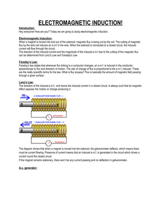
  • 1. ELECTROMAGNETIC INDUCTION! Introduction: Hey everyone! How are you? Today we are going to study electromagnetic induction. Electromagnetic Induction: When a magnet is moved into and out of the solenoid, magnetic flux is being cut by the coil. The cutting of magnetic flux by the wire coil induces an e.m.f in the wire. When the solenoid is connected to a closed circuit, the induced current will flow through the circuit. The direction of the induced current and the magnitude of the induced e.m.f due to the cutting of the magnetic flux can be determined from Lenz's Law and Faraday's Law. Faraday’s Law: Faraday’s law states that whenever flux linking to a conductor changes, an e.m.f. is induced in the conductor, perpendicular to flux and direction of motion. The rate of change of flux is proportional to the e.m.f. induced. These are the really scientific terms for the law. What is flux anyway? Flux is basically the amount of magnetic field passing through a given surface. Lenz’s Law: The direction of the induced e.m.f., and hence the induced current in a closed circuit, is always such that its magnetic effect opposes the motion or change producing it. The diagram shows that when a magnet is moved into the solenoid, the galvanometer deflects, which means there must be current flowing. Presence of current means that an induced e.m.f. is generated in the circuit which drives a current round the closed circuit. If the magnet remains stationary, there won’t be any current passing and no deflection in galvanometer. A.c. generator:
  • 2. The a.c. generator transforms mechanical energy into electrical energy, hence it generates electricity. Generator can be modified to an a.c generator by replacing its commutators with two (separate) slip rings. The two slip rings rotate in tandem with the armature (the rectangular coil). Carbon brushes connect the armature to the external circuit. The armature is initially at the vertical position. No magnetic flux is cut and hence no induced current exists. When the armature rotates, the change in magnetic flux increases and the induced current increases until its maximum value at the horizontal position. The direction of the induced current can be determined from Fleming's Right Hand rule. Fleming's Right-Hand Rule is used to determine the direction of the induced current that flows from the wire when there is relative motion with respect to the magnetic field. As the armature continues on its rotation, the change in magnetic flux decreases until at the vertical position, no induced current exists. Now upon reaching the horizontal position again, the induced current is maximum, but the direction of the induced current flowing through the external circuit is reversed. The direction of the induced current (which flows through the external circuit) keeps changing depending on the orientation of the armature. This induced current is also known as alternating current. The current is positive (+) in one direction and negative in the other (-). The smooth rings play an important role in the generation of alternating current.
  • 3. The diagram shows the front view of the armature (A and B shown in the previous diagram). This graph is for one revolution of the coil. The frequency f of the rotation is related to its period T by the equation: f = 1 / T From this equation, we can see that doubling the frequency f means halving the period T. To increase the induced e.m.f. of an a.c. generator, we can ● increase the number of turns on the coil, ● increase the frequency of rotation of coil, ● use stronger permanent magnet, ● use a soft-iron core. Transformers: What is transformer? A transformer is a device that is used to raise or lower down the potential difference of an alternating current. It either increases or decreases the p.d. of an a.c. supply. This is how it looks like:
  • 4. It consists of the primary coil, the core and the secondary coil. ● The primary circuit is the circuit that connected to the input energy source. The current, potential difference and coil (winding) in the primary circuit are called the primary current (Ip), primary potential difference (Vp) and primary coil respectively. ● The core is the ferromagnetic metal wound by the primary and secondary coil. The function of the core is to transfer the changing magnetic flux from the primary coil to the secondary coil. ● The secondary circuit is the circuit that connected to the output of the transformer. The current, potential difference and coil (winding) in the secondary circuit are called the secondary current (Is), secondary potential difference (Vs) and secondary coil respectively. Now this is how a transformer works: 1. A transformer consists of a primary coil and a secondary coil wound on a soft iron core. 2. When an alternating current flows in the primary coil, a changing magnetic flux is generated around the primary coil. 3. The changing magnetic flux is transferred to the secondary coil through the iron core. 4. The changing magnetic flux is cut by the secondary coil, hence induces an e.m.f. in the secondary coil. 5. The magnitude of the output voltage can be controlled by the ratio of the number of primary coil and secondary coil. In a step-up transformer, the e.m.f. of the secondary coil is greater than the e.m.f. of the primary coil. Similarly, in a step-down transformer, the e.m.f. of the secondary coil is less than the e.m.f. of the primary coil. It can be shown that: Vs / Vp = Ns / Np where Vs is the secondary output voltage, Vp is the primary input voltage, Ns are the number of turns in the secondary coil and Np are the number of turns in the primary coil. Ns / Np is called the turns ratio. Power transfer in a transformer:
  • 5. Here we’ll consider an ideal transformer that is 100 % efficient, so power of the primary coil is fully transferred to the secondary coil. Hence, the Principal of Conservation of energy is applied, from where the power in the primary coil = power in the secondary coil. We know the formula P = VI, right? So we can say that: (Ip) (Vp) = (Is) (Vs) where Ip is current in the primary coil, Is is current in the primary coil, Vp is the primary input voltage and Vs is the secondary output voltage. Now coming to a non-ideal transformer, there will always be power loss, i.e. the efficiency is less than 100 %. Efficiency = (Output power / Input power ) x 100% Converting a.c. to d.c.: We know that the electricity supplied to our homes is in the form of a.c.. But we also know that many appliances require d.c.. So how is a.c. converted into d.c.? The use of diode is the solution to this! A diode is a semiconductor device that allows a current to flow easily in one direction only. Simple. When the diode is connected as in Figure A above, where the anode wire is connected to the positive pole and the cathode connected to the negative pole of battery, we say that forward biased diode. A diode will only conduct electricity (turn on a light) when given forward bias. When a diode is connected with reversed polarity as shown in Figure B, where the cathode wire is connected to the positive pole and the anode connected to the negative pole of battery, we say that reverse biased diode . A diode will not conduct electricity (turn off a light) when given reverse bias. Half-wave rectification:
  • 6. Electrical current is supplied to the circuit is an alternating current generated by a transformer. During the positive half cycle of AC, diodes are forward biased so current can flow. Current that flows through the diode to the load (RL) and back toward the transformer. Then the negative AC half cycle, diode does not conduct electric current, because given the reverse bias. Waveform of the current, then, is as shown below: Full-wave Rectification: This is the circuit used for full-wave rectification. The four diodes are connected in series. During the positive half cycle of the input voltage, diodes D1 and D2 will conduct, while D3 and D4 will remain off. The current will take the path ABDEF. Now during the negative half cycle of the input voltage, diodes D1 and D2 will remain off. The current will follow the path FECDBA. Cathode-Ray Oscilloscope:
  • 7. Shown in the diagram is a simple cathode ray oscilloscope. The device consists mainly of a vacuum tube which contains a cathode , anode , grid , X & Y-plates, and a fluorescent screen . When the cathode is heated (by applying a small potential difference across its terminals), it emits electrons (this process is called thermionic emission). Having a potential difference between the cathode and the anode (electrodes), accelerate the emitted electrons towards the anode, forming an electron beam, which passes to fall on the screen. When the fast electron beam strikes the fluorescent screen, a bright visible spot is produced. The grid, which is situated between the electrodes, controls the amount of electrons passing through it there by controlling the intensity of the electron beam. The X & Y-plates, are responsible for deflecting the electron beam horizontally and vertically. The front panel of the CRO looks like this: The Y-gain of the CRO amplifies the Y-deflection. Amplifying circuits are built into the CRO so that small input voltages are amplified before they are applied to the Y-plates. Time-base controls the speed at which the electron beam sweeps across the screen horizontally from left to right. The settings of the CRO are set, for example time base is set at 0.5 ms/div (0.5 millisecond per division) and the Y- gain is set at 1 V/div (1 volt per division).
  • 8. And this is how the trace will look like: Here you can be asked to find the frequency and the peak voltage. We know that frequency f is f = 1 / T. How many divisions across the x-axis is the wave covering? It’s almost five. So T = 0.5 * 5 = 2.5 ms For frequency, we need to change it to seconds. Now for the peak voltage, the wave is covering two divisions, so it will be V = 1 * 2 = 2V. Task: Find more questions on CRO for practice.