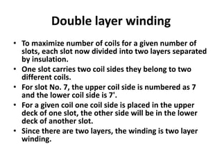
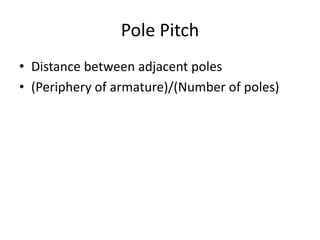
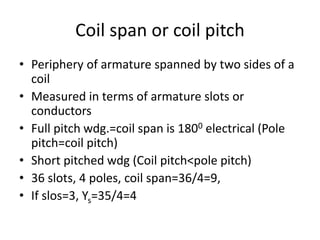
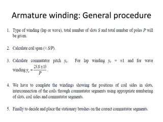
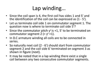
- The document discusses winding fundamentals for DC machines, including definitions of terms like coil, coil span, double layer winding, commutator segment, and commutator pitch.
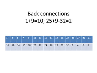
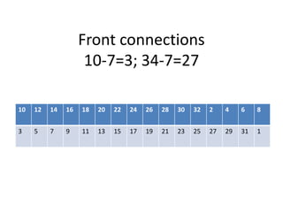
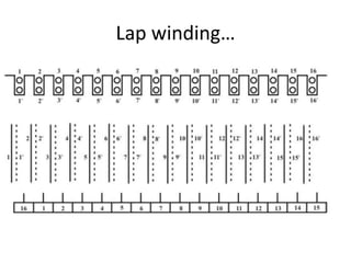
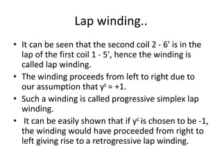
- It provides examples of calculating coil span and explains lap and wave windings, including how to number coils and connect them to commutator segments.
- For a 16-slot, 4-pole lap winding example, it shows how the coils are numbered and connected in a progressive fashion from left to right on the commutator.