SlideShare a Scribd company logo
1 of 21
Download to read offline
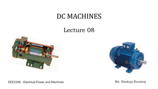
Lecture 08
Ms. Hinduja Durairaj
EEE2306 - Electrical Power and Machines
DC MACHINES
Introduction
Introduction
Basic Structure of DC Machines
Armature Winding Of A DC Machine
• Basically armature winding of a DC machine is wound by one of the two methods:
• The difference between these two is merely due to the end connections and
commutator connections of the conductor.
Armature Winding Of A DC Machine
To know how armature winding is done, the following terminologies are essential:
➢ Pole pitch: It is defined as number of armature slots per pole.
For example, if there are 36 conductors and 4 poles, then the pole pitch is 36/4=9.
➢ Coil span or coil pitch (Yc):
It is the distance between
the two sides of a coil measured
in terms of armature slots.
Armature Winding Of A DC Machine
➢ Front pitch (Yf):
It is the distance, in terms of armature conductors, between the
second conductor of one coil and the first conductor of the next
coil. OR it is the distance between two coil sides that are
connected to the same commutator segment.
➢ Back pitch (Yb):
The distance by which a coil advances on the back of the armature
is called as back pitch of the coil. It is measured in terms of
armature conductors.
➢ Resultant pitch (Yr):
The distance, in terms of armature conductor, between the
beginning of one coil and the beginning of the next coil is called as
resultant pitch of the coil.
Lap Winding
• This is called a lap winding, because as the winding progresses, the coil laps back on
itself. It progresses in a continuous loop fashion.
• In a simplex lap winding, the two ends of a coil are connected to adjacent commutator
segments.
• It is useful for low voltage and high current machines.
• All the conductors in a group are connected
in series and all such groups are connected in parallel.
Number of parallel paths (A) = Number of Poles(P)
Lap Winding
• In a four-pole machine, there are four parallel paths between the positive and negative
terminals of the armature.
• In a lap winding, the number of parallel paths (A) is always equal to the number of
poles (p), and also to the number of brushes.
Lap Winding
• The winding may be progressive or retrogressive.
Lap Winding
• The winding may be progressive or retrogressive.
• A progressive winding progresses in the direction in which the coil is wound.
• The opposite way is retrogressive.
Wave Winding
• A conductor under one pole is connected at the back to a conductor which occupies an
almost corresponding position under the next pole which is of opposite polarity.
• This winding will create only two parallel paths independent of the number of poles.
• Wave winding is useful for high voltage low current capacity machines
• The number of parallel paths for
wave winding will be
less than that for lap winding.
Number of parallel paths (A) = 2
Wave Winding
• In a four-pole machine, there are only two parallel paths between the positive and
negative terminals of the armature.
• In a wave winding, the number of parallel paths (A) is always two.
Difference between Lap and Wave Winding
Armature Winding Of A DC Machine
• Armature winding can be done as single layer or double layer.
• It may be simplex, duplex or multiplex, and this multiplicity increases the number of
parallel paths.
Armature Voltage
• As the armature rotates in the magnetic field produced by the stator poles, voltage is
induced in the armature winding.
• Lets considering the induced voltage in the coils due to change of flux linkage
(Faraday’s law) or by using the concept of “conductor cutting flux.”
• A turn is made of two conductors, the induced voltage in a turn is:
Armature Voltage
Armature Voltage
Armature Voltage
The voltages induced in all the turns connected in series for one parallel path across the
positive and negative brushes will contribute to the average terminal voltage.
Armature Voltage
• Z is the total number of conductors in the armature winding.
• This expression for induced voltage in the armature winding is independent of whether
the machine operates as a generator or a motor.
• In the case of generator operation, it is known as a generated voltage, and in motor
operation it is known as back emf (electromotive force).

More Related Content

Similar to Lecture 08 slides Dc machines and power.pdf

Design of armature for dc motor
Design of armature for dc motorDesign of armature for dc motor
Design of armature for dc motordharmesh nakum
 
Handouts dc machines
Handouts dc machinesHandouts dc machines
Handouts dc machinesSamMendoza17
 
Handouts dc machines
Handouts dc machinesHandouts dc machines
Handouts dc machinesSamMendoza17
 
ENERGY_CONVERSION)During Motor Principle.ppt
ENERGY_CONVERSION)During Motor Principle.pptENERGY_CONVERSION)During Motor Principle.ppt
ENERGY_CONVERSION)During Motor Principle.pptdatamboli
 
INDUCTION MOTOR
INDUCTION MOTORINDUCTION MOTOR
INDUCTION MOTORstudent
 
Unit 3- DC Machines.pdf
Unit 3- DC Machines.pdfUnit 3- DC Machines.pdf
Unit 3- DC Machines.pdfdeepaMS4
 
Beie unit-3
Beie  unit-3Beie  unit-3
Beie unit-3W3Edify
 
Synchmachine-1.ppt
Synchmachine-1.pptSynchmachine-1.ppt
Synchmachine-1.pptdeepaMS4
 
Electromagnetic induction
Electromagnetic inductionElectromagnetic induction
Electromagnetic inductionUgyenNamgay4
 
Incomplete PPT on first topic.pptx [Autosaved] [Autosaved].ppt
Incomplete PPT on first topic.pptx [Autosaved] [Autosaved].pptIncomplete PPT on first topic.pptx [Autosaved] [Autosaved].ppt
Incomplete PPT on first topic.pptx [Autosaved] [Autosaved].pptShubhobrataRudr
 
UNIT-2-DC GENERATOR.ppt
UNIT-2-DC GENERATOR.pptUNIT-2-DC GENERATOR.ppt
UNIT-2-DC GENERATOR.pptKarthik Kathan
 

Similar to Lecture 08 slides Dc machines and power.pdf (20)

Design of armature for dc motor
Design of armature for dc motorDesign of armature for dc motor
Design of armature for dc motor
 
Handouts dc machines
Handouts dc machinesHandouts dc machines
Handouts dc machines
 
Handouts dc machines
Handouts dc machinesHandouts dc machines
Handouts dc machines
 
ENERGY_CONVERSION)During Motor Principle.ppt
ENERGY_CONVERSION)During Motor Principle.pptENERGY_CONVERSION)During Motor Principle.ppt
ENERGY_CONVERSION)During Motor Principle.ppt
 
Synchmachine
SynchmachineSynchmachine
Synchmachine
 
INDUCTION MOTOR
INDUCTION MOTORINDUCTION MOTOR
INDUCTION MOTOR
 
Alternator
AlternatorAlternator
Alternator
 
I introduction 2
I introduction 2I introduction 2
I introduction 2
 
I introduction
I introductionI introduction
I introduction
 
PPT of DC machine.pptx
PPT of DC machine.pptxPPT of DC machine.pptx
PPT of DC machine.pptx
 
Unit 3- DC Machines.pdf
Unit 3- DC Machines.pdfUnit 3- DC Machines.pdf
Unit 3- DC Machines.pdf
 
Module4.pptx
Module4.pptxModule4.pptx
Module4.pptx
 
DC Generators
DC GeneratorsDC Generators
DC Generators
 
Beie unit-3
Beie  unit-3Beie  unit-3
Beie unit-3
 
Synchmachine-1.ppt
Synchmachine-1.pptSynchmachine-1.ppt
Synchmachine-1.ppt
 
Synchmachine-1.ppt
Synchmachine-1.pptSynchmachine-1.ppt
Synchmachine-1.ppt
 
Dc machiness
Dc machinessDc machiness
Dc machiness
 
Electromagnetic induction
Electromagnetic inductionElectromagnetic induction
Electromagnetic induction
 
Incomplete PPT on first topic.pptx [Autosaved] [Autosaved].ppt
Incomplete PPT on first topic.pptx [Autosaved] [Autosaved].pptIncomplete PPT on first topic.pptx [Autosaved] [Autosaved].ppt
Incomplete PPT on first topic.pptx [Autosaved] [Autosaved].ppt
 
UNIT-2-DC GENERATOR.ppt
UNIT-2-DC GENERATOR.pptUNIT-2-DC GENERATOR.ppt
UNIT-2-DC GENERATOR.ppt
 

Recently uploaded

DeepFakes presentation : brief idea of DeepFakes
DeepFakes presentation : brief idea of DeepFakesDeepFakes presentation : brief idea of DeepFakes
DeepFakes presentation : brief idea of DeepFakesMayuraD1
 
Block diagram reduction techniques in control systems.ppt
Block diagram reduction techniques in control systems.pptBlock diagram reduction techniques in control systems.ppt
Block diagram reduction techniques in control systems.pptNANDHAKUMARA10
 
kiln thermal load.pptx kiln tgermal load
kiln thermal load.pptx kiln tgermal loadkiln thermal load.pptx kiln tgermal load
kiln thermal load.pptx kiln tgermal loadhamedmustafa094
 
A CASE STUDY ON CERAMIC INDUSTRY OF BANGLADESH.pptx
A CASE STUDY ON CERAMIC INDUSTRY OF BANGLADESH.pptxA CASE STUDY ON CERAMIC INDUSTRY OF BANGLADESH.pptx
A CASE STUDY ON CERAMIC INDUSTRY OF BANGLADESH.pptxmaisarahman1
 
Hazard Identification (HAZID) vs. Hazard and Operability (HAZOP): A Comparati...
Hazard Identification (HAZID) vs. Hazard and Operability (HAZOP): A Comparati...Hazard Identification (HAZID) vs. Hazard and Operability (HAZOP): A Comparati...
Hazard Identification (HAZID) vs. Hazard and Operability (HAZOP): A Comparati...soginsider
 
Hostel management system project report..pdf
Hostel management system project report..pdfHostel management system project report..pdf
Hostel management system project report..pdfKamal Acharya
 
Thermal Engineering Unit - I & II . ppt
Thermal Engineering  Unit - I & II . pptThermal Engineering  Unit - I & II . ppt
Thermal Engineering Unit - I & II . pptDineshKumar4165
 
AIRCANVAS[1].pdf mini project for btech students
AIRCANVAS[1].pdf mini project for btech studentsAIRCANVAS[1].pdf mini project for btech students
AIRCANVAS[1].pdf mini project for btech studentsvanyagupta248
 
Thermal Engineering -unit - III & IV.ppt
Thermal Engineering -unit - III & IV.pptThermal Engineering -unit - III & IV.ppt
Thermal Engineering -unit - III & IV.pptDineshKumar4165
 
Rums floating Omkareshwar FSPV IM_16112021.pdf
Rums floating Omkareshwar FSPV IM_16112021.pdfRums floating Omkareshwar FSPV IM_16112021.pdf
Rums floating Omkareshwar FSPV IM_16112021.pdfsmsksolar
 
Thermal Engineering-R & A / C - unit - V
Thermal Engineering-R & A / C - unit - VThermal Engineering-R & A / C - unit - V
Thermal Engineering-R & A / C - unit - VDineshKumar4165
 
Navigating Complexity: The Role of Trusted Partners and VIAS3D in Dassault Sy...
Navigating Complexity: The Role of Trusted Partners and VIAS3D in Dassault Sy...Navigating Complexity: The Role of Trusted Partners and VIAS3D in Dassault Sy...
Navigating Complexity: The Role of Trusted Partners and VIAS3D in Dassault Sy...Arindam Chakraborty, Ph.D., P.E. (CA, TX)
 
School management system project Report.pdf
School management system project Report.pdfSchool management system project Report.pdf
School management system project Report.pdfKamal Acharya
 
Online food ordering system project report.pdf
Online food ordering system project report.pdfOnline food ordering system project report.pdf
Online food ordering system project report.pdfKamal Acharya
 
HAND TOOLS USED AT ELECTRONICS WORK PRESENTED BY KOUSTAV SARKAR
HAND TOOLS USED AT ELECTRONICS WORK PRESENTED BY KOUSTAV SARKARHAND TOOLS USED AT ELECTRONICS WORK PRESENTED BY KOUSTAV SARKAR
HAND TOOLS USED AT ELECTRONICS WORK PRESENTED BY KOUSTAV SARKARKOUSTAV SARKAR
 
DC MACHINE-Motoring and generation, Armature circuit equation
DC MACHINE-Motoring and generation, Armature circuit equationDC MACHINE-Motoring and generation, Armature circuit equation
DC MACHINE-Motoring and generation, Armature circuit equationBhangaleSonal
 
Engineering Drawing focus on projection of planes
Engineering Drawing focus on projection of planesEngineering Drawing focus on projection of planes
Engineering Drawing focus on projection of planesRAJNEESHKUMAR341697
 
Generative AI or GenAI technology based PPT
Generative AI or GenAI technology based PPTGenerative AI or GenAI technology based PPT
Generative AI or GenAI technology based PPTbhaskargani46
 

Recently uploaded (20)

DeepFakes presentation : brief idea of DeepFakes
DeepFakes presentation : brief idea of DeepFakesDeepFakes presentation : brief idea of DeepFakes
DeepFakes presentation : brief idea of DeepFakes
 
Block diagram reduction techniques in control systems.ppt
Block diagram reduction techniques in control systems.pptBlock diagram reduction techniques in control systems.ppt
Block diagram reduction techniques in control systems.ppt
 
kiln thermal load.pptx kiln tgermal load
kiln thermal load.pptx kiln tgermal loadkiln thermal load.pptx kiln tgermal load
kiln thermal load.pptx kiln tgermal load
 
A CASE STUDY ON CERAMIC INDUSTRY OF BANGLADESH.pptx
A CASE STUDY ON CERAMIC INDUSTRY OF BANGLADESH.pptxA CASE STUDY ON CERAMIC INDUSTRY OF BANGLADESH.pptx
A CASE STUDY ON CERAMIC INDUSTRY OF BANGLADESH.pptx
 
Hazard Identification (HAZID) vs. Hazard and Operability (HAZOP): A Comparati...
Hazard Identification (HAZID) vs. Hazard and Operability (HAZOP): A Comparati...Hazard Identification (HAZID) vs. Hazard and Operability (HAZOP): A Comparati...
Hazard Identification (HAZID) vs. Hazard and Operability (HAZOP): A Comparati...
 
Hostel management system project report..pdf
Hostel management system project report..pdfHostel management system project report..pdf
Hostel management system project report..pdf
 
Thermal Engineering Unit - I & II . ppt
Thermal Engineering  Unit - I & II . pptThermal Engineering  Unit - I & II . ppt
Thermal Engineering Unit - I & II . ppt
 
AIRCANVAS[1].pdf mini project for btech students
AIRCANVAS[1].pdf mini project for btech studentsAIRCANVAS[1].pdf mini project for btech students
AIRCANVAS[1].pdf mini project for btech students
 
Thermal Engineering -unit - III & IV.ppt
Thermal Engineering -unit - III & IV.pptThermal Engineering -unit - III & IV.ppt
Thermal Engineering -unit - III & IV.ppt
 
Rums floating Omkareshwar FSPV IM_16112021.pdf
Rums floating Omkareshwar FSPV IM_16112021.pdfRums floating Omkareshwar FSPV IM_16112021.pdf
Rums floating Omkareshwar FSPV IM_16112021.pdf
 
Thermal Engineering-R & A / C - unit - V
Thermal Engineering-R & A / C - unit - VThermal Engineering-R & A / C - unit - V
Thermal Engineering-R & A / C - unit - V
 
FEA Based Level 3 Assessment of Deformed Tanks with Fluid Induced Loads
FEA Based Level 3 Assessment of Deformed Tanks with Fluid Induced LoadsFEA Based Level 3 Assessment of Deformed Tanks with Fluid Induced Loads
FEA Based Level 3 Assessment of Deformed Tanks with Fluid Induced Loads
 
Navigating Complexity: The Role of Trusted Partners and VIAS3D in Dassault Sy...
Navigating Complexity: The Role of Trusted Partners and VIAS3D in Dassault Sy...Navigating Complexity: The Role of Trusted Partners and VIAS3D in Dassault Sy...
Navigating Complexity: The Role of Trusted Partners and VIAS3D in Dassault Sy...
 
Call Girls in South Ex (delhi) call me [🔝9953056974🔝] escort service 24X7
Call Girls in South Ex (delhi) call me [🔝9953056974🔝] escort service 24X7Call Girls in South Ex (delhi) call me [🔝9953056974🔝] escort service 24X7
Call Girls in South Ex (delhi) call me [🔝9953056974🔝] escort service 24X7
 
School management system project Report.pdf
School management system project Report.pdfSchool management system project Report.pdf
School management system project Report.pdf
 
Online food ordering system project report.pdf
Online food ordering system project report.pdfOnline food ordering system project report.pdf
Online food ordering system project report.pdf
 
HAND TOOLS USED AT ELECTRONICS WORK PRESENTED BY KOUSTAV SARKAR
HAND TOOLS USED AT ELECTRONICS WORK PRESENTED BY KOUSTAV SARKARHAND TOOLS USED AT ELECTRONICS WORK PRESENTED BY KOUSTAV SARKAR
HAND TOOLS USED AT ELECTRONICS WORK PRESENTED BY KOUSTAV SARKAR
 
DC MACHINE-Motoring and generation, Armature circuit equation
DC MACHINE-Motoring and generation, Armature circuit equationDC MACHINE-Motoring and generation, Armature circuit equation
DC MACHINE-Motoring and generation, Armature circuit equation
 
Engineering Drawing focus on projection of planes
Engineering Drawing focus on projection of planesEngineering Drawing focus on projection of planes
Engineering Drawing focus on projection of planes
 
Generative AI or GenAI technology based PPT
Generative AI or GenAI technology based PPTGenerative AI or GenAI technology based PPT
Generative AI or GenAI technology based PPT
 

Lecture 08 slides Dc machines and power.pdf

  • 1. Lecture 08 Ms. Hinduja Durairaj EEE2306 - Electrical Power and Machines DC MACHINES
  • 4. Basic Structure of DC Machines
  • 5. Armature Winding Of A DC Machine • Basically armature winding of a DC machine is wound by one of the two methods: • The difference between these two is merely due to the end connections and commutator connections of the conductor.
  • 6. Armature Winding Of A DC Machine To know how armature winding is done, the following terminologies are essential: ➢ Pole pitch: It is defined as number of armature slots per pole. For example, if there are 36 conductors and 4 poles, then the pole pitch is 36/4=9. ➢ Coil span or coil pitch (Yc): It is the distance between the two sides of a coil measured in terms of armature slots.
  • 7. Armature Winding Of A DC Machine ➢ Front pitch (Yf): It is the distance, in terms of armature conductors, between the second conductor of one coil and the first conductor of the next coil. OR it is the distance between two coil sides that are connected to the same commutator segment. ➢ Back pitch (Yb): The distance by which a coil advances on the back of the armature is called as back pitch of the coil. It is measured in terms of armature conductors. ➢ Resultant pitch (Yr): The distance, in terms of armature conductor, between the beginning of one coil and the beginning of the next coil is called as resultant pitch of the coil.
  • 8. Lap Winding • This is called a lap winding, because as the winding progresses, the coil laps back on itself. It progresses in a continuous loop fashion. • In a simplex lap winding, the two ends of a coil are connected to adjacent commutator segments. • It is useful for low voltage and high current machines. • All the conductors in a group are connected in series and all such groups are connected in parallel. Number of parallel paths (A) = Number of Poles(P)
  • 9. Lap Winding • In a four-pole machine, there are four parallel paths between the positive and negative terminals of the armature. • In a lap winding, the number of parallel paths (A) is always equal to the number of poles (p), and also to the number of brushes.
  • 10. Lap Winding • The winding may be progressive or retrogressive.
  • 11. Lap Winding • The winding may be progressive or retrogressive. • A progressive winding progresses in the direction in which the coil is wound. • The opposite way is retrogressive.
  • 12. Wave Winding • A conductor under one pole is connected at the back to a conductor which occupies an almost corresponding position under the next pole which is of opposite polarity. • This winding will create only two parallel paths independent of the number of poles. • Wave winding is useful for high voltage low current capacity machines • The number of parallel paths for wave winding will be less than that for lap winding. Number of parallel paths (A) = 2
  • 13. Wave Winding • In a four-pole machine, there are only two parallel paths between the positive and negative terminals of the armature. • In a wave winding, the number of parallel paths (A) is always two.
  • 14. Difference between Lap and Wave Winding
  • 15. Armature Winding Of A DC Machine • Armature winding can be done as single layer or double layer. • It may be simplex, duplex or multiplex, and this multiplicity increases the number of parallel paths.
  • 16.
  • 17. Armature Voltage • As the armature rotates in the magnetic field produced by the stator poles, voltage is induced in the armature winding. • Lets considering the induced voltage in the coils due to change of flux linkage (Faraday’s law) or by using the concept of “conductor cutting flux.” • A turn is made of two conductors, the induced voltage in a turn is:
  • 20. Armature Voltage The voltages induced in all the turns connected in series for one parallel path across the positive and negative brushes will contribute to the average terminal voltage.
  • 21. Armature Voltage • Z is the total number of conductors in the armature winding. • This expression for induced voltage in the armature winding is independent of whether the machine operates as a generator or a motor. • In the case of generator operation, it is known as a generated voltage, and in motor operation it is known as back emf (electromotive force).