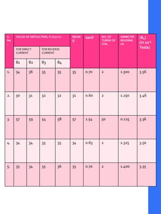
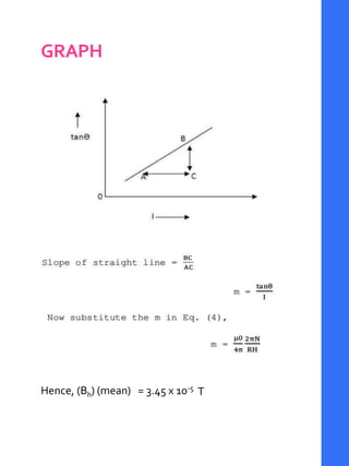
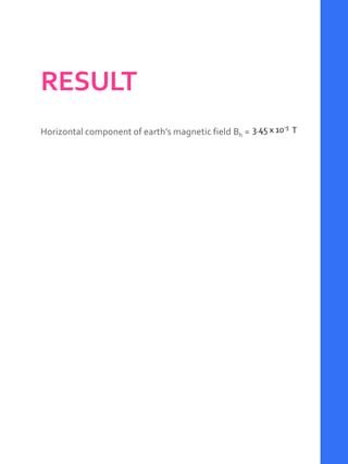
PHYSICS PROJECT
TOSTUDYTHE EARTH
MAGNETIC FIELDUSING
TANGENT
GALVANOMETER
BY PALLAVI SARIN
CLASS:
SUBJECT: PHYSICS
SESSION:
SCHOOL:
ROLL NO.
CERTIFICATE
This is to certify that XXXXX XXXXX of class XXX ,
XXXXX School, XXXXXX has successfully completed
the investigatory project titled “TO STUDY THE
EARTH MAGNETIC FIELD’S MAGNETIC FIELD USING
TANGENT GALVANOMETER ” under the guidance and
supervision of Ms. XXXXX XXXXX (Physics Teacher)
during the year 2XXX-2XXX in the partial fulfillment of
the Physics practical examination conducted by the
CBSE. It is further certified that this project is the
individual and bonafide work of the candidate. This
project in my opinion is completed and ready for
presentation.
EXTERNAL EXAMINER SUBJECTTEACHER
(Ms. XXXXX XXXXX)
ACKNOWLEDGEMENT
I would like to express my special thanks of gratitude to my
teacher Ms. XXXX XXXX as well as our principal Ms.XXX
XXXXX who gave me the golden opportunity to do this
wonderful project on the topic “TO STUDY THE EARTH
MAGNETIC FIELD USING TANGENT GALVANOMETER
”, which also helped me in gaining knowledge about the
topic and in learning new things. I take this opportunity to
express my deep sense of gratitude for her invaluable
guidance, constant encouragement, constructive comments,
sympathetic attitude and immense motivation, which has
sustained my efforts at all stages of this project work. I am
really thankful to them.
Secondly I would also like to thank my parents and friends
who encouraged me and supported me to do the project to
the best of my ability.
INDEX
1. AIM
2. APPARATUS
3. PRINCIPLES APPLIED AND
THEORY
4. PROCEDURE
5. OBSERVATION
6. RESULT
7. PRECAUTIONS
8. BIBLIOGRAPHY
AIM
•TO STUDYTHE EARTH
MAGNETIC FIELD’S
MAGNETIC FIELD USING
TANGENT GALVANOMETER
APPARATUS REQUIRED
• APPARATUS
• Tangent galvanometer (TG)
• Commutator (C)
• Rheostat (R)
• Battery (E)
• Ammeter (A)
• Key (k)
• Spirit level
• Meter scale
• Thread
• Connecting wires
• Sand paper
HISTORYANDOVERVIEW
• A tangent galvanometer is an early measuring
instrument used for the measurement of electric
current. It works by using a compass needle to compare
a magnetic field generated by the unknown current to
the magnetic field of the Earth. It gets its name from its
operating principle, the tangent law of magnetism,
which states that the tangent of the angle a compass
needle makes is proportional to the ratio of the
strengths of the two perpendicular magnetic fields. It
was first described by Claude Pouillet in 1837, who later
employed this sensitive form of galvanometer to verify
Ohm’s law.
• To use the galvanometer, it is first set up on a level surface and
the coil aligned with the magnetic north-south direction. This
means that the compass needle at the middle of the coil is
parallel with the plane of the coil when it carries no current. The
current to be measured is now sent through the coil, and
produces a magnetic field, perpendicular to the plane of the coil
and is directly proportional to the current.
• The magnitude of the magnetic field produced by the coil is B;
the magnitude of the horizontal component the Earth’s magnetic
field is B’. the compass needle aligns itself along the vector sum
of B and B’ after rotating through an angle Ø from its original
orientation. The vector diagram shows that tan Ø = B/B’. since the
magnetic field of the Earth is constant, and B depends directly on
the current, the current is thus proportional to the tangent of the
angle through which the needle has turned.
THEORY
• Tangent galvanometer is an early measuring instrument
for small electric currents. It consists of a coil of
insulated copper wire wound on a circular non-magnetic
frame. Its working is based on the principle of the
tangent law of magnetism. When a current is passed
through the circular coil, a magnetic field (B) is produced
at the center of the coil in a direction perpendicular to
the plane of the coil. The TG is arranged in such a way
that the horizontal component of earth’s magnetic field
(Bh) is in the direction of the plane of the coil. The
magnetic needle is then under the action of two
mutually perpendicular fields. If θ is the deflection of the
needle, then according to tangent law,
• Let I is the current passing through the coil of radius a
with n turns, then the field generated by the current
carrying circular coil is,
• Equating (1) and (2), we get,
• Using equation (4), the value of Bh can be obtained.
• The left hand side of equation (4) is a constant and is
called the reduction factor (K) of the given tangent
galvanometer.
• Now from equation (3) & (5), the horizontal intensity of
earth’s magnetic field Bh is,
• APPLICATIONS
• T.G can be used to measure the magnitude of the
horizontal component of the geomagnetic field.
• The principle can be used to compare the galvanometer
constants.
One problem with the tangent galvanometer is that its
resolution degrades at both high currents and low currents.
The maximum resolution is obtained when the value of θ is
45°. When the value of θ is close to 0° or 90°, a large
percentage change in the current will only move the needle a
few degrees
FACTS
• The tangent galvanometer is an early measuring instrument
for Current
• The magnetic field produced by a circular coil carrying
current I is Proportional to I
• The S.I unit of magnetic field is Tesla
• The magnitude of horizontal intensity of earth’s magnetic
field is 3.5x10⁻⁵ T
• For better result while doing tangent galvanometer
experiment, the deflection should be in between 30-60
degrees.
• The value of μ₀ is 4πx10⁻⁷ NA⁻² .
PROCEDURE
• INITIAL SETUP
• Connections are made as shown in the figure given
below, where K is the key, E the battery, A the ammeter,
R the rheostat, C the commutator, and T.G the tangent
galvanometer. The commutator can reverse the current
through the T.G coil without changing the current in the
rest of the circuit. Taking the average of the resulting
two readings for deflection averages out, any small error
in positioning the TG coil relative to the earth’s magnetic
field H .
• PROCEDURE FOR PERFORMINGTHE
EXPERIMENT
• 1. Make the circuit connections in accordance with the circuit
diagram.
• 2. Using spirit level, level the base and the compass needle in
compass box of tangent galvanometer by adjusting the levelling
screw.
• 3. Now rotate the coil of the galvanometer about its vertical axis,
till the magnetic needle, its image in the plane mirror fixed at the
base of the compass box and the coil, i.e. these three lie in the
same vertical plane.
• 4.In this setting, the ends of the aluminium pointer should read
zero-zero. If this is not so, rotate the box without disturbing the
position of the coil till at least one of the ends of the pointer stands
at the zero marks.
• 5. By closing the key K, the current flow in the galvanometer. Read
the both ends of the pointer. Now reverse the direction of current
by using the reversing key. When the mean values of both
deflections shown by the pointer in the two cases (i.e. before and
after reversing the current) differ by more than 1o, then turn
slightly the vertical coil until the two values agree. This will set the
plane of the coil exactly in the magnetic meridian.
• 6. By adjusting the rheostat, bring the deflection in
galvanometer around 45 degrees.The deflection should not
be outside the range (30-6o degrees).
• 7. Record the reading of the ammeter and the deflection of
the compass needle in the box shown by two ends of pointer
on the scale.
• 8. Reverse the current in the coil of galvanometer and again
record the current and deflection of needle.
• 9. By changing the value of current, take four or more set of
readings and plot the graph between I and tan𝜃.The graph
will be a straight line.
• 10. Measure the circumference of the galvanometer coil
carefully using a thread and a metre scale.
OBSERVATIONS
• Number of turns in the coil =
• Circumference of the coil = 2πa =
• Radius of the coil =
• Range of ammeter =
• Least count of ammeter =
• Zero error of ammeter =
• The Horizontal component of earth's magnetic field (Bh) can be
calculated using the formula,
S.
No
.
VALUE OF DEFLECTION, θ (degree) MEAN
θ
tanθ NO. OF
TURNS OF
COIL
AMMETER
READING
(A)
(Bh)
(in 10-5
Tesla)FOR DIRECT
CURRENT
FOR REVERSE
CURRENT
θ1 θ2 θ3 θ4
1. 34 36 35 35 35 0.70 2 1.500 3.56
2. 30 31 32 32 31 0.60 2 1.250 3.46
3. 57 59 54 58 57 1.54 50 0.125 3.36
4. 34 34 35 35 34 0.63 2 1.325 3.50
5. 35 34 35 36 35 0.70 2 1.400 3.35
GRAPH
Hence, (Bh) (mean) = 3.45 x 10⁻⁵
T
RESULT
Horizontal component of earth’s magnetic field Bh =
PRECAUTIONS
1. The battery should be freshly charged.
2. The magnetic needle should swing freely in the
horizontal plane.
3. The plane of coil must be set in magnetic meridian.
4. There should be no parallax in noting down the
readings of ammeter and deflection.
5. All the readings should be adjusted between 30 and
60 degrees.
SOURCES OF ERROR
1. There may a magnetic material around apparatus.
2. The plane of coil will not be exactly in the magnetic
meridian.
BIBLIOGRAPHY
• Google Images
• NCERT Physics Laboratory Manual Class XII
• www.physicsstackexchange.com/
• https://en.wikipedia.org/wiki/Tangent_galvanometer
• https://en.wikipedia.org/wiki/commutator
• http://physics.kenyon.edu/EarlyApparatus/Electrical_Me
asurements/Tangent_Galvanometer/Tangent_Galvanom
eter.html

investigatory project Physics

  • 1.
    PHYSICS PROJECT TOSTUDYTHE EARTH MAGNETICFIELDUSING TANGENT GALVANOMETER BY PALLAVI SARIN CLASS: SUBJECT: PHYSICS SESSION: SCHOOL: ROLL NO.
  • 2.
    CERTIFICATE This is tocertify that XXXXX XXXXX of class XXX , XXXXX School, XXXXXX has successfully completed the investigatory project titled “TO STUDY THE EARTH MAGNETIC FIELD’S MAGNETIC FIELD USING TANGENT GALVANOMETER ” under the guidance and supervision of Ms. XXXXX XXXXX (Physics Teacher) during the year 2XXX-2XXX in the partial fulfillment of the Physics practical examination conducted by the CBSE. It is further certified that this project is the individual and bonafide work of the candidate. This project in my opinion is completed and ready for presentation. EXTERNAL EXAMINER SUBJECTTEACHER (Ms. XXXXX XXXXX)
  • 3.
    ACKNOWLEDGEMENT I would liketo express my special thanks of gratitude to my teacher Ms. XXXX XXXX as well as our principal Ms.XXX XXXXX who gave me the golden opportunity to do this wonderful project on the topic “TO STUDY THE EARTH MAGNETIC FIELD USING TANGENT GALVANOMETER ”, which also helped me in gaining knowledge about the topic and in learning new things. I take this opportunity to express my deep sense of gratitude for her invaluable guidance, constant encouragement, constructive comments, sympathetic attitude and immense motivation, which has sustained my efforts at all stages of this project work. I am really thankful to them. Secondly I would also like to thank my parents and friends who encouraged me and supported me to do the project to the best of my ability.
  • 4.
    INDEX 1. AIM 2. APPARATUS 3.PRINCIPLES APPLIED AND THEORY 4. PROCEDURE 5. OBSERVATION 6. RESULT 7. PRECAUTIONS 8. BIBLIOGRAPHY
  • 5.
    AIM •TO STUDYTHE EARTH MAGNETICFIELD’S MAGNETIC FIELD USING TANGENT GALVANOMETER
  • 6.
    APPARATUS REQUIRED • APPARATUS •Tangent galvanometer (TG) • Commutator (C) • Rheostat (R) • Battery (E) • Ammeter (A) • Key (k) • Spirit level • Meter scale • Thread • Connecting wires • Sand paper
  • 7.
    HISTORYANDOVERVIEW • A tangentgalvanometer is an early measuring instrument used for the measurement of electric current. It works by using a compass needle to compare a magnetic field generated by the unknown current to the magnetic field of the Earth. It gets its name from its operating principle, the tangent law of magnetism, which states that the tangent of the angle a compass needle makes is proportional to the ratio of the strengths of the two perpendicular magnetic fields. It was first described by Claude Pouillet in 1837, who later employed this sensitive form of galvanometer to verify Ohm’s law.
  • 8.
    • To usethe galvanometer, it is first set up on a level surface and the coil aligned with the magnetic north-south direction. This means that the compass needle at the middle of the coil is parallel with the plane of the coil when it carries no current. The current to be measured is now sent through the coil, and produces a magnetic field, perpendicular to the plane of the coil and is directly proportional to the current. • The magnitude of the magnetic field produced by the coil is B; the magnitude of the horizontal component the Earth’s magnetic field is B’. the compass needle aligns itself along the vector sum of B and B’ after rotating through an angle Ø from its original orientation. The vector diagram shows that tan Ø = B/B’. since the magnetic field of the Earth is constant, and B depends directly on the current, the current is thus proportional to the tangent of the angle through which the needle has turned.
  • 9.
    THEORY • Tangent galvanometeris an early measuring instrument for small electric currents. It consists of a coil of insulated copper wire wound on a circular non-magnetic frame. Its working is based on the principle of the tangent law of magnetism. When a current is passed through the circular coil, a magnetic field (B) is produced at the center of the coil in a direction perpendicular to the plane of the coil. The TG is arranged in such a way that the horizontal component of earth’s magnetic field (Bh) is in the direction of the plane of the coil. The magnetic needle is then under the action of two mutually perpendicular fields. If θ is the deflection of the needle, then according to tangent law, • Let I is the current passing through the coil of radius a with n turns, then the field generated by the current carrying circular coil is,
  • 10.
    • Equating (1)and (2), we get, • Using equation (4), the value of Bh can be obtained. • The left hand side of equation (4) is a constant and is called the reduction factor (K) of the given tangent galvanometer. • Now from equation (3) & (5), the horizontal intensity of earth’s magnetic field Bh is, • APPLICATIONS • T.G can be used to measure the magnitude of the horizontal component of the geomagnetic field. • The principle can be used to compare the galvanometer constants.
  • 11.
    One problem withthe tangent galvanometer is that its resolution degrades at both high currents and low currents. The maximum resolution is obtained when the value of θ is 45°. When the value of θ is close to 0° or 90°, a large percentage change in the current will only move the needle a few degrees FACTS • The tangent galvanometer is an early measuring instrument for Current • The magnetic field produced by a circular coil carrying current I is Proportional to I • The S.I unit of magnetic field is Tesla • The magnitude of horizontal intensity of earth’s magnetic field is 3.5x10⁻⁵ T • For better result while doing tangent galvanometer experiment, the deflection should be in between 30-60 degrees. • The value of μ₀ is 4πx10⁻⁷ NA⁻² .
  • 12.
    PROCEDURE • INITIAL SETUP •Connections are made as shown in the figure given below, where K is the key, E the battery, A the ammeter, R the rheostat, C the commutator, and T.G the tangent galvanometer. The commutator can reverse the current through the T.G coil without changing the current in the rest of the circuit. Taking the average of the resulting two readings for deflection averages out, any small error in positioning the TG coil relative to the earth’s magnetic field H .
  • 13.
    • PROCEDURE FORPERFORMINGTHE EXPERIMENT • 1. Make the circuit connections in accordance with the circuit diagram. • 2. Using spirit level, level the base and the compass needle in compass box of tangent galvanometer by adjusting the levelling screw. • 3. Now rotate the coil of the galvanometer about its vertical axis, till the magnetic needle, its image in the plane mirror fixed at the base of the compass box and the coil, i.e. these three lie in the same vertical plane. • 4.In this setting, the ends of the aluminium pointer should read zero-zero. If this is not so, rotate the box without disturbing the position of the coil till at least one of the ends of the pointer stands at the zero marks. • 5. By closing the key K, the current flow in the galvanometer. Read the both ends of the pointer. Now reverse the direction of current by using the reversing key. When the mean values of both deflections shown by the pointer in the two cases (i.e. before and after reversing the current) differ by more than 1o, then turn slightly the vertical coil until the two values agree. This will set the plane of the coil exactly in the magnetic meridian.
  • 14.
    • 6. Byadjusting the rheostat, bring the deflection in galvanometer around 45 degrees.The deflection should not be outside the range (30-6o degrees). • 7. Record the reading of the ammeter and the deflection of the compass needle in the box shown by two ends of pointer on the scale. • 8. Reverse the current in the coil of galvanometer and again record the current and deflection of needle. • 9. By changing the value of current, take four or more set of readings and plot the graph between I and tan𝜃.The graph will be a straight line. • 10. Measure the circumference of the galvanometer coil carefully using a thread and a metre scale.
  • 15.
    OBSERVATIONS • Number ofturns in the coil = • Circumference of the coil = 2πa = • Radius of the coil = • Range of ammeter = • Least count of ammeter = • Zero error of ammeter = • The Horizontal component of earth's magnetic field (Bh) can be calculated using the formula,
  • 16.
    S. No . VALUE OF DEFLECTION,θ (degree) MEAN θ tanθ NO. OF TURNS OF COIL AMMETER READING (A) (Bh) (in 10-5 Tesla)FOR DIRECT CURRENT FOR REVERSE CURRENT θ1 θ2 θ3 θ4 1. 34 36 35 35 35 0.70 2 1.500 3.56 2. 30 31 32 32 31 0.60 2 1.250 3.46 3. 57 59 54 58 57 1.54 50 0.125 3.36 4. 34 34 35 35 34 0.63 2 1.325 3.50 5. 35 34 35 36 35 0.70 2 1.400 3.35
  • 17.
    GRAPH Hence, (Bh) (mean)= 3.45 x 10⁻⁵ T
  • 18.
    RESULT Horizontal component ofearth’s magnetic field Bh =
  • 19.
    PRECAUTIONS 1. The batteryshould be freshly charged. 2. The magnetic needle should swing freely in the horizontal plane. 3. The plane of coil must be set in magnetic meridian. 4. There should be no parallax in noting down the readings of ammeter and deflection. 5. All the readings should be adjusted between 30 and 60 degrees. SOURCES OF ERROR 1. There may a magnetic material around apparatus. 2. The plane of coil will not be exactly in the magnetic meridian.
  • 20.
    BIBLIOGRAPHY • Google Images •NCERT Physics Laboratory Manual Class XII • www.physicsstackexchange.com/ • https://en.wikipedia.org/wiki/Tangent_galvanometer • https://en.wikipedia.org/wiki/commutator • http://physics.kenyon.edu/EarlyApparatus/Electrical_Me asurements/Tangent_Galvanometer/Tangent_Galvanom eter.html