This document defines several basic concepts related to electric machines:
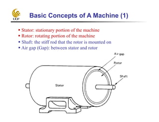
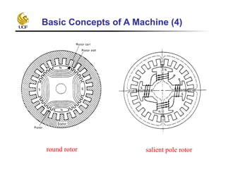
- The stator is the stationary part, and the rotor is the rotating part connected to the shaft. An air gap separates the stator and rotor.
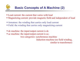
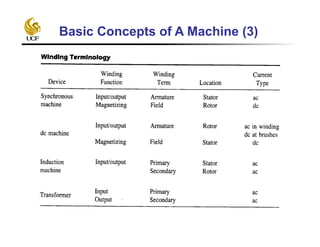
- Machines can be DC or AC depending on the input/output current type. AC machines include synchronous and induction machines.
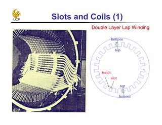
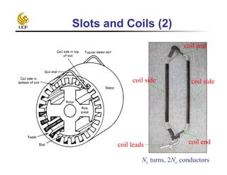
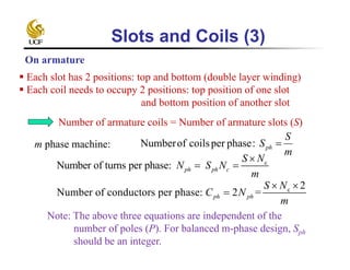
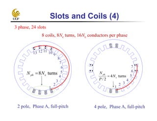
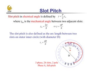
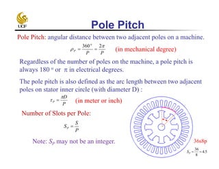
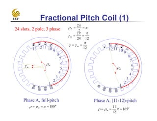
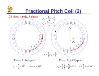
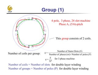
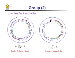
- Other concepts defined include the armature, field windings, load and magnetizing currents, slots/coils configuration, pole/slot pitch, and fractional vs full pitch coils.
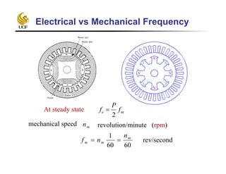
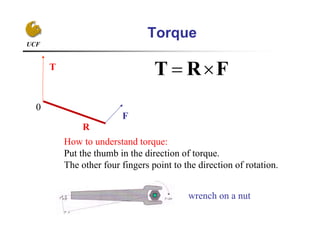
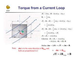
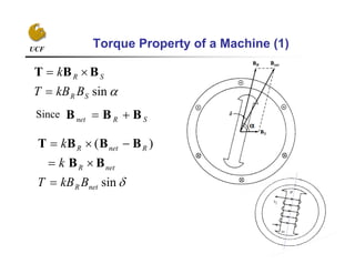
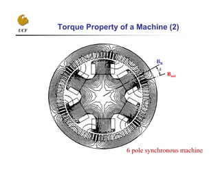
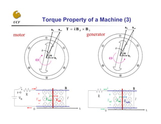
- The torque produced in a current loop is proportional to the cross product of the magnetic field and current. The torque produced in a machine depends on the sine of the rotor position and
Output equation of Induction motor; Main dimensions; Separation of D and L; Choice of Average flux density; length of air gap; Design of Stator core; Rules for selecting rotor slots of squirrel cage machines; Design of rotor bars and slots; Design of end rings; Design of wound rotor; Magnetic leakage calculations; Leakage reactance of polyphase machines; Magnetizing current; Short circuit current; Operating characteristics; Losses and Efficiency.
The armature winding is the main current-carrying winding in which the electromotive force or counter-emf of rotation is induced.
The current in the armature winding is known as the armature current.
The location of the winding depends upon the type of machine.
The armature windings of dc motors are located on the rotor, since they must operate in union with the commutator.
In DC rotating machines other than brushless DC machines, it is usually rotating.
An alternator is an electrical generator that converts mechanical energy to electrical energy in the form of alternating current. For reasons of cost and simplicity, most alternators use a rotating magnetic field with a stationary armature.
The single-phase motor, which are designed to operate from a single-phase supply, are manufactured in a large number of types to perform a wide variety of useful services in home, offices, factories, workshops and in a business establishments etc.
Small motors, particularly in the frictional kW sizes are better known than any other. In fact, most of the new products of the manufacturers of space vehicles, aircrafts, business machines and power tools etc. have been possible due to of the advances made in the design of frictional kW motors. Since the performance requirements of the various applications differ so widely, the motor manufacturing industry has developed many different types of such motors, each being designed to meet specific demands.
Single-phase motors may be classified as under, depending on their construction and method of starting:
1. Induction Motors (split-phase, capacitor and shaded-pole etc.)
2. Repulsion Motors (sometime called inductive-series motor)
3. AC Series Motor, and
4. Un-excited Synchronous Motors
PPTs deals with the Unit 5 of Power Plant Engineering, discusses Load Curve, Load duration curve, various factors associated with power palnt like Load factor, capacity factor, use factor, demand factor , diversity factor, method of calculating different costs involved in power generation, differential fuel costing and its implications on sharing of units, factors determine the selection of site for Power plants Workedout problems are also dealt
This presentation describes the per-phase equivalent circuit of induction motor - Power flow diagram - Ratio of air gap power, rotor copper loss and mechanical power developed.
Consists of two sets of windings:
3 phase armature winding on the stator distributed with centres 120° apart in space
field winding on the rotor supplied by DC
Two basic rotor structures used:
salient or projecting pole structure for hydraulic units (low speed)
round rotor structure for thermal units (high speed)
Salient poles have concentrated field windings; usually also carry damper windings on the pole face.Round rotors have solid steel rotors with distributed windings
Nearly sinusoidal space distribution of flux wave shape obtained by:
distributing stator windings and field windings in many slots (round rotor);
shaping pole faces (salient pole)
Physical Description
Mathematical Model
Park's "dqo" transportation
Steady-state Analysis
phasor representation in d-q coordinates
link with network equations
Definition of "rotor angle"
Representation of Synchronous Machines in Stability Studies
neglect of stator transients
magnetic saturation
Simplified Models
Synchronous Machine Parameters
Reactive Capability Limits
Consists of two sets of windings:
3 phase armature winding on the stator distributed with centres 120° apart in space
field winding on the rotor supplied by DC
Two basic rotor structures used:
salient or projecting pole structure for hydraulic units (low speed)
round rotor structure for thermal units (high speed)
Salient poles have concentrated field windings; usually also carry damper windings on the pole face.Round rotors have solid steel rotors with distributed windings
Nearly sinusoidal space distribution of flux wave shape obtained by:
distributing stator windings and field windings in many slots (round rotor);
shaping pole faces (salient pole)
CFD Simulation of By-pass Flow in a HRSG module by R&R Consult.pptxR&R Consult
CFD analysis is incredibly effective at solving mysteries and improving the performance of complex systems!
Here's a great example: At a large natural gas-fired power plant, where they use waste heat to generate steam and energy, they were puzzled that their boiler wasn't producing as much steam as expected.
R&R and Tetra Engineering Group Inc. were asked to solve the issue with reduced steam production.
An inspection had shown that a significant amount of hot flue gas was bypassing the boiler tubes, where the heat was supposed to be transferred.
R&R Consult conducted a CFD analysis, which revealed that 6.3% of the flue gas was bypassing the boiler tubes without transferring heat. The analysis also showed that the flue gas was instead being directed along the sides of the boiler and between the modules that were supposed to capture the heat. This was the cause of the reduced performance.
Based on our results, Tetra Engineering installed covering plates to reduce the bypass flow. This improved the boiler's performance and increased electricity production.
It is always satisfying when we can help solve complex challenges like this. Do your systems also need a check-up or optimization? Give us a call!
Work done in cooperation with James Malloy and David Moelling from Tetra Engineering.
More examples of our work https://www.r-r-consult.dk/en/cases-en/
Immunizing Image Classifiers Against Localized Adversary Attacksgerogepatton
This paper addresses the vulnerability of deep learning models, particularly convolutional neural networks
(CNN)s, to adversarial attacks and presents a proactive training technique designed to counter them. We
introduce a novel volumization algorithm, which transforms 2D images into 3D volumetric representations.
When combined with 3D convolution and deep curriculum learning optimization (CLO), itsignificantly improves
the immunity of models against localized universal attacks by up to 40%. We evaluate our proposed approach
using contemporary CNN architectures and the modified Canadian Institute for Advanced Research (CIFAR-10
and CIFAR-100) and ImageNet Large Scale Visual Recognition Challenge (ILSVRC12) datasets, showcasing
accuracy improvements over previous techniques. The results indicate that the combination of the volumetric
input and curriculum learning holds significant promise for mitigating adversarial attacks without necessitating
adversary training.
Welcome to WIPAC Monthly the magazine brought to you by the LinkedIn Group Water Industry Process Automation & Control.
In this month's edition, along with this month's industry news to celebrate the 13 years since the group was created we have articles including
A case study of the used of Advanced Process Control at the Wastewater Treatment works at Lleida in Spain
A look back on an article on smart wastewater networks in order to see how the industry has measured up in the interim around the adoption of Digital Transformation in the Water Industry.
Cosmetic shop management system project report.pdfKamal Acharya
Buying new cosmetic products is difficult. It can even be scary for those who have sensitive skin and are prone to skin trouble. The information needed to alleviate this problem is on the back of each product, but it's thought to interpret those ingredient lists unless you have a background in chemistry.
Instead of buying and hoping for the best, we can use data science to help us predict which products may be good fits for us. It includes various function programs to do the above mentioned tasks.
Data file handling has been effectively used in the program.
The automated cosmetic shop management system should deal with the automation of general workflow and administration process of the shop. The main processes of the system focus on customer's request where the system is able to search the most appropriate products and deliver it to the customers. It should help the employees to quickly identify the list of cosmetic product that have reached the minimum quantity and also keep a track of expired date for each cosmetic product. It should help the employees to find the rack number in which the product is placed.It is also Faster and more efficient way.
About
Indigenized remote control interface card suitable for MAFI system CCR equipment. Compatible for IDM8000 CCR. Backplane mounted serial and TCP/Ethernet communication module for CCR remote access. IDM 8000 CCR remote control on serial and TCP protocol.
• Remote control: Parallel or serial interface.
• Compatible with MAFI CCR system.
• Compatible with IDM8000 CCR.
• Compatible with Backplane mount serial communication.
• Compatible with commercial and Defence aviation CCR system.
• Remote control system for accessing CCR and allied system over serial or TCP.
• Indigenized local Support/presence in India.
• Easy in configuration using DIP switches.
Technical Specifications
Indigenized remote control interface card suitable for MAFI system CCR equipment. Compatible for IDM8000 CCR. Backplane mounted serial and TCP/Ethernet communication module for CCR remote access. IDM 8000 CCR remote control on serial and TCP protocol.
Key Features
Indigenized remote control interface card suitable for MAFI system CCR equipment. Compatible for IDM8000 CCR. Backplane mounted serial and TCP/Ethernet communication module for CCR remote access. IDM 8000 CCR remote control on serial and TCP protocol.
• Remote control: Parallel or serial interface
• Compatible with MAFI CCR system
• Copatiable with IDM8000 CCR
• Compatible with Backplane mount serial communication.
• Compatible with commercial and Defence aviation CCR system.
• Remote control system for accessing CCR and allied system over serial or TCP.
• Indigenized local Support/presence in India.
Application
• Remote control: Parallel or serial interface.
• Compatible with MAFI CCR system.
• Compatible with IDM8000 CCR.
• Compatible with Backplane mount serial communication.
• Compatible with commercial and Defence aviation CCR system.
• Remote control system for accessing CCR and allied system over serial or TCP.
• Indigenized local Support/presence in India.
• Easy in configuration using DIP switches.
Saudi Arabia stands as a titan in the global energy landscape, renowned for its abundant oil and gas resources. It's the largest exporter of petroleum and holds some of the world's most significant reserves. Let's delve into the top 10 oil and gas projects shaping Saudi Arabia's energy future in 2024.
2. Stator: stationary portion of the machine
Rotor: rotating portion of the machine
Shaft: the stiff rod that the rotor is mounted on
Air gap (Gap): between stator and rotor
Basic Concepts of A Machine (1)
3. Basic Concepts of A Machine (2)
Load current: the current that varies with load
Magnetizing current: provide magnetic field and independent of load
Armature: the winding that carries only load current
Field: the winding that carries only magnetizing current
dc machine: the input/output current is dc
ac machine: the input/output current is ac;
two categories: synchronous machine
induction machine (no field winding,
similar to transformer)
6. Electrical vs Mechanical Frequency
At steady state me f
P
f
2
N
N
N
N
S
S S
S
mnmechanical speed revolution/minute (rpm)
6060
1 m
mm
n
nf rev/second
7. Slots and Coils (1)
tooth
slot
top
top
bottom
bottom
Double Layer Lap Winding
8. Slots and Coils (2)
coil side coil side
coil end
coil endcoil leads
Nc turns, 2Nc conductors
9. Slots and Coils (3)
Each slot has 2 positions: top and bottom (double layer winding)
Each coil needs to occupy 2 positions: top position of one slot
and bottom position of another slot
Number of armature coils = Number of armature slots (S)
m phase machine:
m
S
Sph:phasepercoilsofNumber
c
Number of turns per phase: ph ph c
S N
N S N
m
c 2
Number of conductors per phase: 2 =ph ph
S N
C N
m
On armature
Note: The above three equations are independent of the
number of poles (P). For balanced m-phase design, Sph
should be an integer.
10. 1
2 3
4
5
6
7
Slots and Coils (4)
3 phase, 24 slots
2 pole, Phase A, full-pitch 4 pole, Phase A, full-pitch
8 coils, 8Nc turns, 16Nc conductors per phase
1
2
3
4
5
6
7
8
910111213
turns8 cNNph
turns4
2/
cN
P
N ph
11. Slot Pitch
Slot pitch in electrical angle is defined by m
P
2
where m is the mechanical angle between two adjacent slots:
S
m
2
S
P
The slot pitch is also defined as the arc length between two
slots on stator inner circle (with diameter D):
S
D
s
1
2
3
4
5
6
7
8
910111213
m
D
3 phase, 24 slots, 2 pole
Phase A, full-pitch
12. Pole Pitch
PP
P
2360o
Pole Pitch: angular distance between two adjacent poles on a machine.
(in mechanical degree)
Regardless of the number of poles on the machine, a pole pitch is
always 180 o or in electrical degrees.
The pole pitch is also defined as the arc length between two adjacent
poles on stator inner circle (with diameter D) :
Number of Slots per Pole:
P
S
SP
P
D
P
(in meter or inch)
36s8pNote: SP may not be an integer.
5.4
8
36
PS
13. Coil Pitch
Let Sc be the number of slots that the coil spans.
Let m be the mechanical angle that the coil spans or
Coil pitch in electrical angle is defined by
P
c
P
m
S
S
2
m
P
Full-Pitch Coil: If the armature coil stretches across the same angle as
the pole pitch, it is called a full-pitch coil. The coil spans across SP
slots, if SP is an integer.
Fractional-Pitch Coil: If the armature coil stretches across an angle
smaller than a pole pitch, it is called a fractional-pitch coil (or short-
pitched coil, chorded coil) . The coil spans less than SP slots.
.m cm S
14. Fractional Pitch Coil (1)
Phase A, full-pitch Phase A, (11/12)-pitch
1
2
3
4
5
6
7
8
9101112
24 slots, 2 pole, 3 phase
2
2
P
o
180 m o
165
12
11
m
m
1
2
3
4
5
6
7
8
910111213
m
1224
2
m
12
m
m
16. Group (1)
4 pole, 3 phase, 24 slot machine
Phase A, (5/6)-pitch
This group consists of 2 coils.
Number of coils per group: )(polesofNumber)(phasesofNumber
)(SlotsStatorofNumber
Pm
S
q
Number of groups = Number of poles (P) for double layer winding
P
S
q
3
for 3 phase machine
Number of coils = Number of slots for double layer winding
18. UCF
Torque
0
R
F
T
How to understand torque:
Put the thumb in the direction of torque.
The other four fingers point to the direction of rotation.
FRT
wrench on a nut
19. UCF
Torque from a Current Loop
Likewise
Define
Bloop
Note: dm is in the same direction of Bloop and
both are proportional to I
dm = k Bloop
BBT loopkd
1
1
1 1 1
3 3 3
1
1 3
( )
1
2
1
( )
2
1
2
1
( )( )
2
1
2
x y z z y
y
y y z z y
y x
y y z z y
y x
y x
d Idx Idx B B
dy
d d dy Idx B B
dxdyIB
d d dy Idx B B
dxdyIB d
d d dxdyIB
F a B a a
R a
T R F a a a
a
T R F a a a
a T
T T a
2 4
( )
x y
z
d d dxdyIB
Idxdy Id
T T a
a B S B
d Idm S d d T m B
20. UCF
Torque Property of a Machine (1)
sinSR
SR
BkBT
k
BBT
Since SRnet BBB
sin
)(
netR
netR
RnetR
BkBT
k
k
BB
BBBT