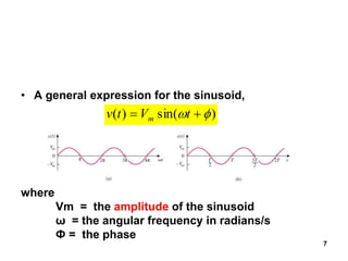
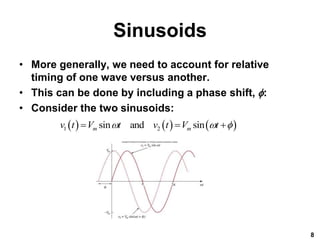
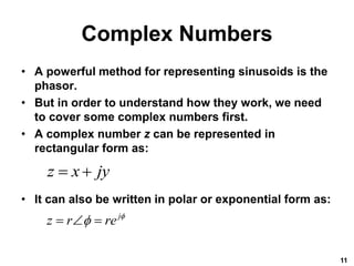
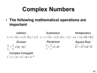
This document provides an overview of sinusoidal steady-state analysis of circuits containing resistors, capacitors, and inductors. It introduces alternating current and defines sinusoids. Phasors are presented as a way to represent sinusoids in frequency domain by using complex numbers. Circuit element relationships are mapped to the phasor domain, including impedance and admittance. Kirchhoff's laws are shown to apply to phasor analysis. Methods for combining impedance elements in series and parallel are described.
1. Network Theory and Analysis
Unit 1
Sinusoidal Steady-State Analysis
By
B. Surya Prasada Rao
Associate Professor
Dept. of ECE, PVPSIT
1
2. Overview
• This chapter will cover alternating current.
• A discussion of complex numbers is
included prior to introducing phasors.
• Applications of phasors and frequency
domain analysis for circuits including
resistors, capacitors, and inductors will be
covered.
• The concept of impedance and admittance is
also introduced.
2
3. Alternating Current
• Alternating Current, or AC, is the dominant
form of electrical power that is delivered to
homes and industry.
• In the late 1800’s there was a battle between
proponents of DC and AC.
• AC won out due to its efficiency for long
distance transmission.
• AC is a sinusoidal current, meaning the
current reverses at regular times and has
alternating positive and negative values.
3
4. Sinusoids
• Sinusoids are interesting to us because there
are a number of natural phenomenon that are
sinusoidal in nature.
• It is also a very easy to generate signal and
transmit.
• Also, through Fourier analysis, any practical
periodic function can be made by adding
sinusoids.
• Lastly, they are very easy to handle
mathematically.
4
5. Sinusoids
• A sinusoidal forcing function produces both a
transient and a steady state response.
• When the transient has died out, we say the circuit is
in sinusoidal steady state.
• A sinusoidal voltage may be represented as:
• From the waveform equation, one characteristic is
clear: The function repeats itself every T seconds.
• This is called the period
5
sin
m
v t V t
2
T
6. Sinusoids
• The period is inversely related to another
important characteristic, the frequency
• The units of this is cycles per second, or
Hertz (Hz)
• It is often useful to refer to frequency in
angular terms:
• Here the angular frequency is in radians per
second
6
1
f
T
2 f
7. 7
• A general expression for the sinusoid,
where
Vm = the amplitude of the sinusoid
ω = the angular frequency in radians/s
Ф = the phase
)
sin(
)
(
t
V
t
v m
8. Sinusoids
• More generally, we need to account for relative
timing of one wave versus another.
• This can be done by including a phase shift, :
• Consider the two sinusoids:
8
1 2
sin and sin
m m
v t V t v t V t
9. 9
Example 1
Given a sinusoid, , calculate its
amplitude, phase, angular frequency, period, and
frequency.
Solution:
Amplitude = 5, phase = –60o, angular frequency
= 4 rad/s, Period = 0.5 s, frequency = 2 Hz.
)
60
4
sin(
5 o
t
10. Sinusoids
• If two sinusoids are in phase, then this
means that they reach their maximum and
minimum at the same time.
• Sinusoids may be expressed as sine or
cosine.
• The conversion between them is:
10
sin 180 sin
cos 180 cos
sin 90 cos
cos 90 sin
t t
t t
t t
t t
11. Complex Numbers
• A powerful method for representing sinusoids is the
phasor.
• But in order to understand how they work, we need
to cover some complex numbers first.
• A complex number z can be represented in
rectangular form as:
• It can also be written in polar or exponential form as:
11
z x jy
j
z r re
12. Complex Numbers
• The different forms can be
interconverted.
• Starting with rectangular form,
one can go to polar:
• Likewise, from polar to
rectangular form goes as
follows:
12
2 2 1
tan
y
r x y
x
cos sin
x r y r
13. Complex Numbers
• The following mathematical operations are
important
13
1 2 1 2 1 2 1 2 1 2 1 2 1 2 1 2 1 2
1 1
1 2
2 2
*
1 1
/ 2
j
z z x x j y y z z x x j y y z z rr
z r
z r
z r z r
z x jy r re
Addition Subtraction Multiplication
Division Reciprocal Square Root
Complex Conjugate
14. Phasors
• The idea of a phasor representation is based
on Euler’s identity:
• From this we can represent a sinusoid as the
real component of a vector in the complex
plane.
• The length of the vector is the amplitude of
the sinusoid.
• The vector,V, in polar form, is at an angle
with respect to the positive real axis.
14
cos sin
j
e j
15. 15
• A phasor is a complex
number that represents the
amplitude and phase of a
sinusoid.
• It can be represented in one of
the following three forms:
r
z
j
re
z
)
sin
(cos
j
r
jy
x
z
a. Rectangular
b. Polar
c. Exponential
2
2
y
x
r
x
y
1
tan
where
16. 16
Example 3
• Evaluate the following complex numbers:
a.
b.
Solution:
a. –15.5 + j13.67
b. 8.293 + j2.2
]
60
5
j4)
1
j2)(
[(5 o
o
o
30
10
j4
3
40
3
j5
10
17. Phasors
• Phasors are typically represented at t=0.
• As such, the transformation between time
domain to phasor domain is:
• They can be graphically represented as
shown here.
17
(Phasor-domain
(Time-domain
representation)
representation)
cos
m m
v t V t V V
18. 18
Transform the following sinusoids to phasors:
i = 6cos(50t – 40o) A
v = –4sin(30t + 50o) V
cos (wt +90o )= - sin wt, cos (wt -90o )= sin wt
Solution:
a. I A
b. Since –sin(A) = cos(A+90o);
v(t) = 4cos (30t+50o+90o) = 4cos(30t+140o) V
Transform to phasor => V V
40
6
140
4
20. Sinusoid-Phasor
Transformation
• Note that the frequency of the phasor is not
explicitly shown in the phasor diagram
• For this reason phasor domain is also known
as frequency domain.
• Applying a derivative to a phasor yields:
• Applying an integral to a phasor yeilds:
20
(Phasor domain)
(Time domain)
dv
j V
dt
(Time domain)
(Phasor domain)
V
vdt
j
21. Phasor Relationships for
Resistors
• Each circuit element has a
relationship between its current and
voltage.
• These can be mapped into phasor
relationships very simply for
resistors capacitors and inductor.
• For the resistor, the voltage and
current are related via Ohm’s law.
• As such, the voltage and current are
in phase with each other.
21
22. Phasor Relationships for
Inductors
• Inductors on the other hand have
a phase shift between the voltage
and current.
• In this case, the voltage leads the
current by 90°.
• Or one says the current lags the
voltage, which is the standard
convention.
• This is represented on the phasor
diagram by a positive phase angle
between the voltage and current.
22
23. Phasor Relationships for
Capacitors
• Capacitors have the opposite
phase relationship as
compared to inductors.
• In their case, the current leads
the voltage.
• In a phasor diagram, this
corresponds to a negative
phase angle between the
voltage and current.
23
26. Impedance and Admittance
• It is possible to expand Ohm’s law to capacitors and
inductors.
• In time domain, this would be tricky as the ratios of
voltage and current and always changing.
• But in frequency domain it is straightforward
• The impedance of a circuit element is the ratio of the
phasor voltage to the phasor current.
• Admittance is simply the inverse of impedance.
26
or
V
Z V ZI
I
27. Impedance and Admittance
• It is important to realize that in
frequency domain, the values
obtained for impedance are
only valid at that frequency.
• Changing to a new frequency
will require recalculating the
values.
• The impedance of capacitors
and inductors are shown here:
27
28. Impedance and Admittance
• As a complex quantity, the impedance may
be expressed in rectangular form.
• The separation of the real and imaginary
components is useful.
• The real part is the resistance.
• The imaginary component is called the
reactance, X.
• When it is positive, we say the impedance is
inductive, and capacitive when it is negative.
28
29. Impedance and Admittance
• Admittance, being the reciprocal of the impedance,
is also a complex number.
• It is measured in units of Siemens
• The real part of the admittance is called the
conductance, G
• The imaginary part is called the susceptance, B
• These are all expressed in Siemens or (mhos)
• The impedance and admittance components can be
related to each other:
29
2 2 2 2
R X
G B
R X R X
32. Kirchoff’s Laws in Frequency
Domain
• A powerful aspect of phasors is that
Kirchoff’s laws apply to them as well.
• This means that a circuit transformed to
frequency domain can be evaluated by the
same methodology developed for KVL and
KCL.
• One consequence is that there will likely be
complex values.
32
33. Impedance Combinations
• Once in frequency domain, the impedance
elements are generalized.
• Combinations will follow the rules for
resistors:
33
34. Impedance Combinations
• Series combinations will result in a sum of
the impedance elements:
• Here then two elements in series can act like
a voltage divider
34
1 2
1 2
1 2 1 2
Z Z
V V V V
Z Z Z Z
1 2 3
eq N
Z Z Z Z Z
35. Parallel Combination
• Likewise, elements combined in parallel will
combine in the same fashion as resistors in
parallel:
35
1 2 3
1 1 1 1 1
eq N
Z Z Z Z Z
37. Admittance
• Expressed as admittance, though, they are
again a sum:
• Once again, these elements can act as a
current divider:
37
1 2 3
eq N
Y Y Y Y Y
2 1
1 2
1 2 1 2
Z Z
I I I I
Z Z Z Z
38. Impedance Combinations
• The Delta-Wye transformation is:
38
1
2
3
b c
a b c
c a
a b c
a b
a b c
Z Z
Z
Z Z Z
Z Z
Z
Z Z Z
Z Z
Z
Z Z Z
1 2 2 3 3 1
1
1 2 2 3 3 1
2
1 2 2 3 3 1
3
a
b
c
Z Z Z Z Z Z
Z
Z
Z Z Z Z Z Z
Z
Z
Z Z Z Z Z Z
Z
Z