- The document discusses equations for calculating the induced EMF in alternator windings.
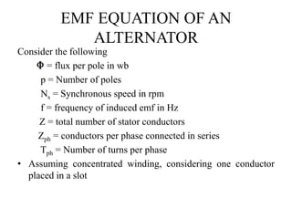
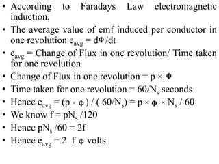
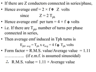
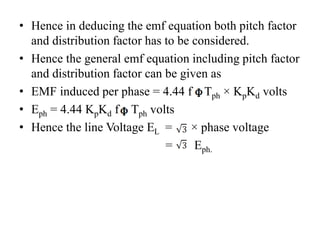
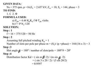
- It derives the basic EMF equation for a concentrated full-pitched winding as Eph=4.44fTph, where f is frequency, Tph is turns per phase.
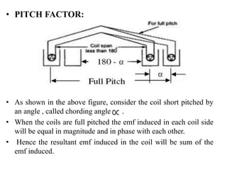
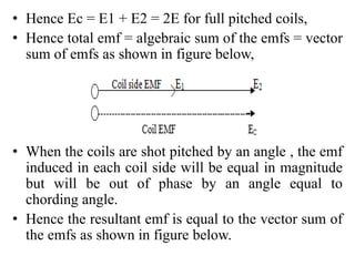
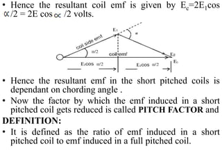
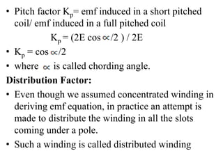
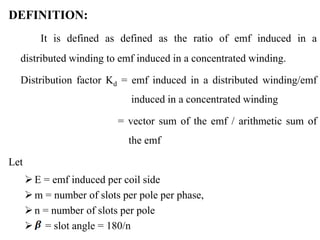
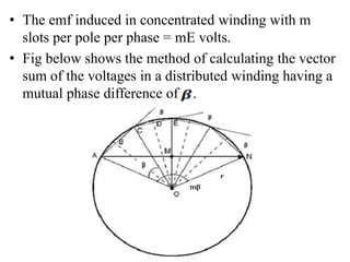
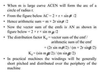
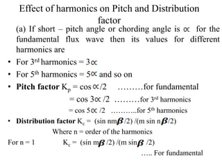
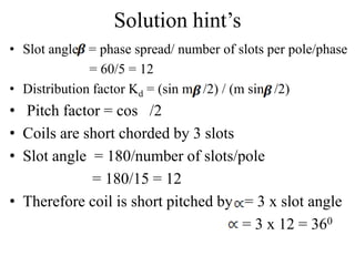
- It introduces pitch factor Kp and distribution factor Kd to account for short-pitched and distributed windings.
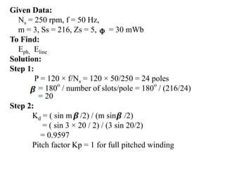
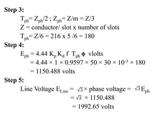
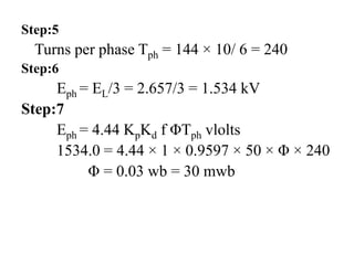
- The general EMF equation is given as Eph=4.44fTphKpKd, accounting for various winding configurations.
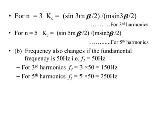
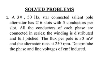
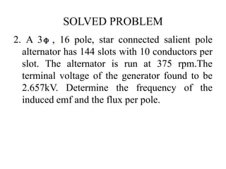
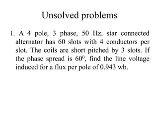
- Examples are given to demonstrate calculating EMF values using the equations.
Software Development Life Cycle By Team Orange (Dept. of Pharmacy)
EMF Equation of an Alternator
1. CONTENTS
EMF EQUATION OF AN ALTERNATOR
For full pitched concentric winding
For short pitched distributed winding
2. EMF EQUATION OF AN
ALTERNATOR
Consider the following
= flux per pole in wb
p = Number of poles
Ns = Synchronous speed in rpm
f = frequency of induced emf in Hz
Z = total number of stator conductors
Zph = conductors per phase connected in series
Tph = Number of turns per phase
• Assuming concentrated winding, considering one conductor
placed in a slot
3. • According to Faradays Law electromagnetic
induction,
• The average value of emf induced per conductor in
one revolution eavg = d /dt
• eavg = Change of Flux in one revolution/ Time taken
for one revolution
• Change of Flux in one revolution = p ×
• Time taken for one revolution = 60/Ns seconds
• Hence eavg = (p × ) / ( 60/Ns) = p × × Ns / 60
• We know f = pNs /120
• Hence pNs /60 = 2f
• Hence eavg = 2 f volts
4. • If there are Z conductors connected in series/phase,
• Hence average emf = 2 × f Z volts
since Z = 2 Tph
• Hence average emf per turn = 4 × f volts
• i.e. If there are Tph, number of turns per phase
connected in series,
• Then average emf induced in Tph turns is
Eph, avg = Tph x eavg = 4 f Tph volts
• Form factor = R.M.S. value/Average value = 1.11
………….. (if e.m.f. is assumed sinusoidal)
R.M.S. value = 1.11 × Average value
5. • Hence RMS value of emf induced/phase
E = 1.11 × Eph, avg
= 1.11 × 4 f Tph volts
• This is the general emf equation for the machine
having concentrated and full pitched winding.
• In practice, alternators will have short pitched
winding and hence coil span will not be 180o, but
on or two slots short than the full pitch.
6. • PITCH FACTOR:
• As shown in the above figure, consider the coil short pitched by
an angle , called chording angle .
• When the coils are full pitched the emf induced in each coil side
will be equal in magnitude and in phase with each other.
• Hence the resultant emf induced in the coil will be sum of the
emf induced.
7. • Hence Ec = E1 + E2 = 2E for full pitched coils,
• Hence total emf = algebraic sum of the emfs = vector
sum of emfs as shown in figure below,
• When the coils are shot pitched by an angle , the emf
induced in each coil side will be equal in magnitude
but will be out of phase by an angle equal to
chording angle.
• Hence the resultant emf is equal to the vector sum of
the emfs as shown in figure below.
8. • Hence the resultant coil emf is given by Ec=2E1cos
/2 = 2E cos /2 volts.
• Hence the resultant emf in the short pitched coils is
dependant on chording angle .
• Now the factor by which the emf induced in a short
pitched coil gets reduced is called PITCH FACTOR and
DEFINITION:
• It is defined as the ratio of emf induced in a short
pitched coil to emf induced in a full pitched coil.
9. • Pitch factor Kp= emf induced in a short pitched
coil/ emf induced in a full pitched coil
Kp = (2E cos /2 ) / 2E
• Kp = cos /2
• where is called chording angle.
Distribution Factor:
• Even though we assumed concentrated winding in
deriving emf equation, in practice an attempt is
made to distribute the winding in all the slots
coming under a pole.
• Such a winding is called distributed winding
10. • In concentrated winding the emf induced in all the
coil sides will be same in magnitude and in phase
with each other.
• In case of distributed winding the magnitude of emf
will be same but the emfs induced in each coil side
will not be in phase with each other as they are
distributed in the slots under a pole.
• The total emf will not be same as that in concentrated
winding but will be equal to the vector sum of the
emfs induced.
• Hence it will be less than that in the concentrated
winding
• The factor by which the emf induced in a distributed
winding gets reduced is called distribution factor
11. DEFINITION:
It is defined as defined as the ratio of emf induced in a
distributed winding to emf induced in a concentrated winding.
Distribution factor Kd = emf induced in a distributed winding/emf
induced in a concentrated winding
= vector sum of the emf / arithmetic sum of
the emf
Let
E = emf induced per coil side
m = number of slots per pole per phase,
n = number of slots per pole
= slot angle = 180/n
12. • The emf induced in concentrated winding with m
slots per pole per phase = mE volts.
• Fig below shows the method of calculating the vector
sum of the voltages in a distributed winding having a
mutual phase difference of .
13. • When m is large curve ACEN will form the arc of a
circle of radius r.
• From the figure below AC = 2 × r × sin /2
• Hence arithmetic sum = m × 2r sin /2
• Now the vector sum of the emfs is AN as shown in
figure below = 2 × r × sin m /2
• The distribution factor Kd = vector sum of the emf /
arithmetic sum of the emf
= (2r sin m /2) / (m × 2r sin /2)
Kd = (sin m /2) / (m sin /2)
• In practical machines the windings will be generally
short pitched and distributed over the periphery of the
machine
14. • Hence in deducing the emf equation both pitch factor
and distribution factor has to be considered.
• Hence the general emf equation including pitch factor
and distribution factor can be given as
• EMF induced per phase = 4.44 f Tph × KpKd volts
• Eph = 4.44 KpKd f Tph volts
• Hence the line Voltage EL = × phase voltage
= Eph.
15. Effect of harmonics on Pitch and Distribution
factor
(a) If short – pitch angle or chording angle is for the
fundamental flux wave then its values for different
harmonics are
• For 3rd harmonics = 3
• For 5th harmonics = 5 and so on
• Pitch factor Kp = cos /2 ………for fundamental
= cos 3 /2 ………for 3rd harmonics
= cos 5 /2 ………..for 5th harmonics
• Distribution factor Kc = (sin nm /2) /(m sin n /2)
Where n = order of the harmonics
For n = 1 Kc = (sin m /2) /(m sin /2)
….. For fundamental
16. • For n = 3 Kc = (sin 3m /2) /(msin3 /2)
…………For 3rd harmonics
• For n = 5 Kc = (sin 5m /2) /(msin5 /2)
……......For 5th harmonics
• (b) Frequency also changes if the fundamental
frequency is 50Hz i.e. f1 = 50Hz
– For 3rd harmonics f3 = 3 ×50 = 150Hz
– For 5th harmonics f5 = 5 ×50 = 250Hz
17. SOLVED PROBLEMS
1. A 3 , 50 Hz, star connected salient pole
alternator has 216 slots with 5 conductors per
slot. All the conductors of each phase are
connected in series; the winding is distributed
and full pitched. The flux per pole is 30 mW
and the alternator runs at 250 rpm. Determinbe
the phase and line voltages of emf induced.
18. Given Data:
Ns = 250 rpm, f = 50 Hz,
m = 3, Ss = 216, Zs = 5, = 30 mWb
To Find:
Eph, Eline
Solution:
Step 1:
P = 120 × f/Ns = 120 × 50/250 = 24 poles
= 180o
/ number of slots/pole = 180o
/ (216/24)
= 20
Step 2:
Kd = ( sin m /2) / (m sin /2)
= ( sin 3 × 20 / 2) / (3 sin 20/2)
= 0.9597
Pitch factor Kp = 1 for full pitched winding
19. Step 3:
Tph= Zph/2 ; Zph= Z/m = Z/3
Z = conductor/ slot x number of slots
Tph= Z/6 = 216 x 5 /6 = 180
Step 4:
Eph = 4.44 Kp Kd f Tph vlolts
= 4.44 × 1 × 0.9597 × 50 × 30 × 10-3 × 180
= 1150.488 volts
Step 5:
Line Voltage ELine = × phase voltage = Eph
= × 1150.488
= 1992.65 volts
20. SOLVED PROBLEM
2. A 3 , 16 pole, star connected salient pole
alternator has 144 slots with 10 conductors per
slot. The alternator is run at 375 rpm.The
terminal voltage of the generator found to be
2.657kV. Determine the frequency of the
induced emf and the flux per pole.
21. GIVEN DATA:
Ns = 375 rpm, p =16,EL = 2.657 kV, Zss = 10, Ss = 144, phase = 3
TO FIND:
1. f, 2. Φ
FORMULA USED:
a) Eph = 4.44 KpKd f Φ Tph vlolts
b) f = P Ns /120
SOLUTION:
Step : 1
f = 16 × 375/120 = 50 Hz
Step : 2
Assuming full pitched winding Kp = 1
Number of slots per pole per phase m = (Ss)/ (p ×phase) = 144/(16 x 3) = 3
Step :3
Slot angle = 1800 / number of slots/pole = 1800/9 = 200
Step :4
Distribution factor Kd = ( sin m /2) / (m sin /2)
= ( sin 3 x 20 / 2) / (3 sin 20/2)
= 0.9597
23. Unsolved problems
1. A 4 pole, 3 phase, 50 Hz, star connected
alternator has 60 slots with 4 conductors per
slot. The coils are short pitched by 3 slots. If
the phase spread is 600, find the line voltage
induced for a flux per pole of 0.943 wb.
24. Solution hint’s
• Slot angle = phase spread/ number of slots per pole/phase
= 60/5 = 12
• Distribution factor Kd = (sin m /2) / (m sin /2)
• Pitch factor = cos /2
• Coils are short chorded by 3 slots
• Slot angle = 180/number of slots/pole
= 180/15 = 12
• Therefore coil is short pitched by = 3 x slot angle
= 3 x 12 = 360