The document discusses different types of DC generator windings, including:
- Lap and wave windings, which determine the number of parallel paths in the generator and its applications.
- Separately and self-excited generators, where the field winding is powered externally or internally.
- Series, shunt, and compound generator windings, and how they determine the voltage and current characteristics of the generator.
V/F control of Induction Motor - Variable voltage and Variable frequencyCitharthan Durairaj
This presentation describes Principle of Variable voltage and Variable frequency- the open loop & closed loop Voltage/Frequency (V/F) control of Induction motor with torque speed characteristics -
Torque - Slip Characteristic of a three phase induction motorAli Altahir
Lecture Objectives:
1-Sketch the torque-slip, with various features.
2- Derive the expression of maximum torque and the corresponding slip which it occurs.
3- Draw the above characteristics with variation in rotor resistance.
Self control of synchronous motor drives
Phase-Controlled Cycloconverters
Synchronous Motor Drive
Self controlled sync. Motor drive using a cycloconverter
Lecture notes on Closed Loop Control of DC Drives.
Electrical Drives, B.Tech. (Electrical) Rajasthan Technical University
Contents:
● Control structure of DC drive
● Inner current loop and outer speed loop
● Dynamic model of dc motor – dynamic equations and transfer
functions
● Modeling of chopper as gain with switching delay, Plant
transfer function for controller design
● Current controller specification and design, Speed controller
specification and design
DC motors
Torque & Speed Equations
Torque -Armature current Characteristics
Speed - Armature current Characteristics
Torque-speed characteristics
Applications
Speed Control
Winding
What is Armature winding?
Terms related to armature winding.
Single layer and double layer windings.
Comparison between closed and open windings.
Types of DC armature winding.
Types of AC armature winding.
Overview of the fundamental roles in Hydropower generation and the components involved in wider Electrical Engineering.
This paper presents the design and construction of hydroelectric dams from the hydrologist’s survey of the valley before construction, all aspects and involved disciplines, fluid dynamics, structural engineering, generation and mains frequency regulation to the very transmission of power through the network in the United Kingdom.
Author: Robbie Edward Sayers
Collaborators and co editors: Charlie Sims and Connor Healey.
(C) 2024 Robbie E. Sayers
Hybrid optimization of pumped hydro system and solar- Engr. Abdul-Azeez.pdffxintegritypublishin
Advancements in technology unveil a myriad of electrical and electronic breakthroughs geared towards efficiently harnessing limited resources to meet human energy demands. The optimization of hybrid solar PV panels and pumped hydro energy supply systems plays a pivotal role in utilizing natural resources effectively. This initiative not only benefits humanity but also fosters environmental sustainability. The study investigated the design optimization of these hybrid systems, focusing on understanding solar radiation patterns, identifying geographical influences on solar radiation, formulating a mathematical model for system optimization, and determining the optimal configuration of PV panels and pumped hydro storage. Through a comparative analysis approach and eight weeks of data collection, the study addressed key research questions related to solar radiation patterns and optimal system design. The findings highlighted regions with heightened solar radiation levels, showcasing substantial potential for power generation and emphasizing the system's efficiency. Optimizing system design significantly boosted power generation, promoted renewable energy utilization, and enhanced energy storage capacity. The study underscored the benefits of optimizing hybrid solar PV panels and pumped hydro energy supply systems for sustainable energy usage. Optimizing the design of solar PV panels and pumped hydro energy supply systems as examined across diverse climatic conditions in a developing country, not only enhances power generation but also improves the integration of renewable energy sources and boosts energy storage capacities, particularly beneficial for less economically prosperous regions. Additionally, the study provides valuable insights for advancing energy research in economically viable areas. Recommendations included conducting site-specific assessments, utilizing advanced modeling tools, implementing regular maintenance protocols, and enhancing communication among system components.
Saudi Arabia stands as a titan in the global energy landscape, renowned for its abundant oil and gas resources. It's the largest exporter of petroleum and holds some of the world's most significant reserves. Let's delve into the top 10 oil and gas projects shaping Saudi Arabia's energy future in 2024.
Industrial Training at Shahjalal Fertilizer Company Limited (SFCL)MdTanvirMahtab2
This presentation is about the working procedure of Shahjalal Fertilizer Company Limited (SFCL). A Govt. owned Company of Bangladesh Chemical Industries Corporation under Ministry of Industries.
Final project report on grocery store management system..pdfKamal Acharya
In today’s fast-changing business environment, it’s extremely important to be able to respond to client needs in the most effective and timely manner. If your customers wish to see your business online and have instant access to your products or services.
Online Grocery Store is an e-commerce website, which retails various grocery products. This project allows viewing various products available enables registered users to purchase desired products instantly using Paytm, UPI payment processor (Instant Pay) and also can place order by using Cash on Delivery (Pay Later) option. This project provides an easy access to Administrators and Managers to view orders placed using Pay Later and Instant Pay options.
In order to develop an e-commerce website, a number of Technologies must be studied and understood. These include multi-tiered architecture, server and client-side scripting techniques, implementation technologies, programming language (such as PHP, HTML, CSS, JavaScript) and MySQL relational databases. This is a project with the objective to develop a basic website where a consumer is provided with a shopping cart website and also to know about the technologies used to develop such a website.
This document will discuss each of the underlying technologies to create and implement an e- commerce website.
Final project report on grocery store management system..pdf
DC Generator tutorial problem
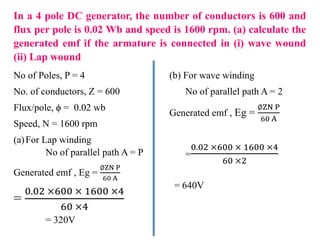
1. In a 4 pole DC generator, the number of conductors is 600 and
flux per pole is 0.02 Wb and speed is 1600 rpm. (a) calculate the
generated emf if the armature is connected in (i) wave wound
(ii) Lap wound
No of Poles, P = 4
No. of conductors, Z = 600
Flux/pole, ϕ = 0.02 wb
Speed, N = 1600 rpm
(a)For Lap winding
No of parallel path A = P
Generated emf , Eg =
∅ZN P
60 A
=
0.02 ×600 × 1600 ×4
60 ×4
= 320V
(b) For wave winding
No of parallel path A = 2
Generated emf , Eg =
∅ZN P
60 A
=
0.02 ×600 × 1600 ×4
60 ×2
= 640V
2. Lap winding; the ends of each armature coils are connected to adjacent
segments on the commutators
so that the total number of parallel paths (A) = total no.of poles (P)
Lap winding A = P
Use in Low voltage high current machines
Wave winding; the ends of each armature coils are connected to
adjacent segments some distance apart, and only two parallel paths are
provided between positive and negative brushes.
For Wave winding A = 2
Use in High voltage Low current machines
Lap Winding
Wave winding
3. A 4 pole DC generator having wave wound armature winding
has 51 slots, each slot containing 20 conductors. Find the
generated voltage in the machine when speed is 1500 rpm and
flux per pole is 60 mWb.
No of Poles, P = 4
No of Slots = 51
No of conductors/slot = 20
Total no. of conductors, Z = 51 × 20 = 1020
Speed, N = 1500 rpm
Flux/pole, ϕ = 60 mwb = 60 × 10 -3
No of parallel path, A = 2 (for wave wound)
Generated emf , Eg =
∅ZN P
60 A
=
60 ×10−3 ×1020 ×1500 ×4
60 ×2
=3060 V
4. The armature of a 4 pole 230 V wave wound generator has 400
conductors and runs at 400 rpm. Calculate the useful flux per pole.
5. An 8 pole lap wound generator has 1000 armature conductors, flux
per pole 20 m Wb and emf generated is 400 V, what is the speed of the
machine?
6.
7. Separately Excited D.C. Generators
A dc generator whose field magnet winding is supplied from an
independent external d.c. source (e.g., a battery etc.) is called a
separately excited generator.
The voltage output depends upon the speed of rotation of armature and
the field current (Eg = φZNP/60 A).
The greater the speed and field current, the greater is the generated e.m.f.
Armature current, Ia = IL
Terminal voltage, V = Eg – IaRa
Electric power developed = EgIa
Power delivered to load = EgIa – I R =
= VIa
8. Self-Excited D.C. Generators
A d.c. generator whose field magnet winding is supplied current from
the output of the generator itself is called a self-excited generator.
Self-excitation is possible only if the field pole pieces have retained a
slight amount of permanent magnetism, called residual magnetism.
When the generator starts rotating, the weak residual magnetism causes a
small voltage to be generated in the armature. This small voltage applied
to the field coils causes a small field current.
Although small, this field current strengthens the magnetic field and
allows the armature to generate a higher voltage. The higher voltage
increases the field strength, and so on. This process continues until the
output voltage reaches the rated output of the generator.
Series generator
Shunt generator
Compound generator
9. DC Series Generator
In a series-wound generator, the field winding is connected in series
with armature winding so that whole armature current flows through the
field winding as well as the load.
Armature current, Ia = Ise = IL = I
Terminal voltage, V = EG – I(Ra + Rse)
Power developed in armature = EgIa
uses very low resistance field coils, which consist of a few turns
of large diameter wire. The voltage output increases as the load
circuit start drawing more current.
10. DC Shunt Generator
In a shunt generator, the field winding is connected in parallel with the
armature winding so that the terminal voltage of the generator is applied across
it.
The shunt field winding has many turns of fine wire having high resistance.
Therefore, only a part of armature current flows through shunt field winding and
the rest flows through the load.
Shunt field current, Ish = V/Rsh
Armature current, Ia = IL + Ish
Terminal voltage, V = Eg – IaRa
Power developed in armature = EgIa
Power delivered to load = VIL
Current in the field windings of a shunt-wound generator is independent of
the load current.
Since field current, and therefore field strength, is not affected by load
current, the output voltage remains more nearly constant.
11. In a series-wound generator, the output voltage varies directly with load
current. In the shunt-wound generator, the output voltage varies
inversely with load current.
A combination of the two types can overcome the disadvantages of both.
This combination of windings is called the compound wound DC
generator.
Short Shunt Compound DC Generator
shunt field winding is in parallel with
the armature winding.
Series field current, Ise = IL
Shunt field current,
Terminal voltage, V = Eg – IaRa – IseRse
Power developed in armature = EgIa
Power delivered to load = VIL
12. Series field current, Ise = Ia = IL + Ish
Shunt field current, Ish = V/Rsh
Terminal voltage, V = Eg – Ia(Ra + Rse)
The power developed in armature = EgI
Power delivered to load = VIL
shunt field winding is in parallel with both series field and armature
winding.
Long shunt Compound Generator
Compound wound generators are of two types, known as cumulative
wound and differential wound generators.
In cumulative wound generators the series field assists the shunt field,
whereas, in differential wound generators, series field opposes the shunt
field. Problems