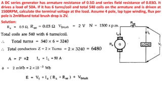
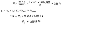
The document describes the symbolic representation and methods of excitation for DC generators. It discusses separately excited, self-excited, shunt, series, and compound generator types. Key points include:
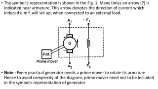
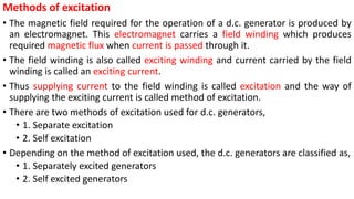
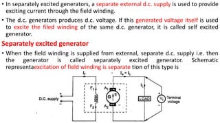
- DC generators use an electromagnet with a field winding to produce a magnetic field for operation. The field winding is excited either separately using an external DC supply, or self-excited using the generator's own output voltage.
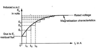
- In a self-excited generator, residual magnetism induces a small voltage to initially power the field winding and build the voltage up to its rated level.
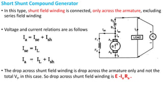
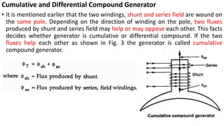
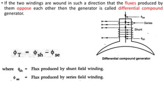
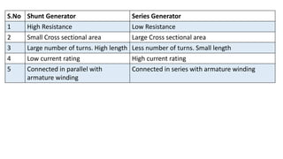
- Shunt, series, and compound generators differ in how their field windings are connected in relation to the armature