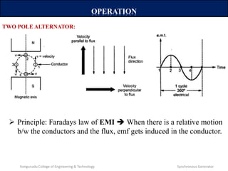
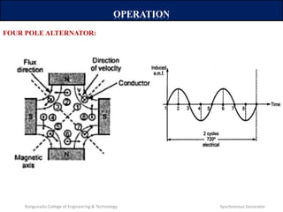
The document discusses synchronous generators and their operation. It covers:
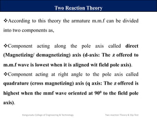
- The two reaction theory which separates the armature mmf into direct and quadrature axis components.
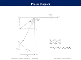
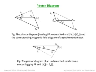
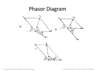
- How phasor diagrams can be used to represent the direct and quadrature axis reactances (Xd and Xq).
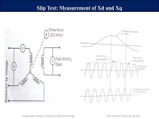
- The slip test method to measure Xd and Xq by taking voltage-to-current ratios with the armature mmf aligned to each axis.
- Important cautions for the slip test including keeping slip extremely low to avoid errors from damper windings or open circuit voltages reaching dangerous levels.