This document provides information on three-phase induction motors:
- It discusses the construction, operation, and advantages/disadvantages of three-phase induction motors. The main components are the stationary stator and revolving rotor, which can be either a squirrel cage or wound type.
- A balanced three-phase supply to the stator produces a rotating magnetic field that induces voltage in the rotor windings, generating torque. The motor runs slightly slower than the synchronous speed due to slip.
- Equivalent circuits are presented for analyzing induction motors, accounting for variables like induced voltage and reactance that change with slip frequency. Power losses and relationships are also examined.
An induction is an AC electric motor in which the electric current in the rotor needed to produce torque is obtained by electromagnetic induction from the magnetic field of the stator winding. An induction motor therefore does not require mechanical commutation, separate-excitation or self-excitation for all or part of the energy transferred from stator to rotor, as in universal, DC and large synchronous motors. An induction motor's rotor can be either wound type or squirrel-cage type.
An induction is an AC electric motor in which the electric current in the rotor needed to produce torque is obtained by electromagnetic induction from the magnetic field of the stator winding. An induction motor therefore does not require mechanical commutation, separate-excitation or self-excitation for all or part of the energy transferred from stator to rotor, as in universal, DC and large synchronous motors. An induction motor's rotor can be either wound type or squirrel-cage type.
Speed control of Three phase Induction motor using AC voltage regulatorShivagee Raj
The role of AC Voltage Regulator in speed control of three phase Induction Motor is to vary the supply voltage which in turn, changes the speed of motor .
This presentation describes the per-phase equivalent circuit of induction motor - Power flow diagram - Ratio of air gap power, rotor copper loss and mechanical power developed.
A synchronous motor is electrically identical with an alternator or AC generator.
A given alternator ( or synchronous machine) can be used as a motor, when driven electrically.
Some characteristic features of a synchronous motor are as follows:
1. It runs either at synchronous speed or not at all i.e. while running it maintains a constant speed. The only way to change its speed is to vary the supply frequency (because NS=120f/P).
2. It is not inherently self-starting. It has to be run up to synchronous (or near synchronous) speed by some means, before it can be synchronized to the supply.
3. It is capable of being operated under a wide range of power factors, both lagging and leading. Hence, it can be used for power correction purposes, in addition to supplying torque to drive loads.
Equivalent circuit diagram of a transformer is basically a diagram which can be resolved into an equivalent circuit in which the resistance and leakage reactance of the transformer are imagined to be external to the winding. Where, R1 = Primary Winding Resistance. R2= Secondary winding Resistance.
Rotating Electrical Machines-AC & DC Machines,Induction Motor and DC MotorPrasant Kumar
Rotating electrical machines,induction machines,induction motor,construction working principle of ac machines,working of dc machines construction of DC motor,starting,torque speed relation,speed control mechanism of dc machines
VTU Notes for Testing and commissioning of Electrical Equipment Department of Electrical and Electronics Faculty Name: Mrs Veena Bhat Designation: Assistant Professor SDM Institute of Technology Subject: Testing and Commissioning of Electrical equipment Semester: VII
Water scarcity is the lack of fresh water resources to meet the standard water demand. There are two type of water scarcity. One is physical. The other is economic water scarcity.
Welcome to WIPAC Monthly the magazine brought to you by the LinkedIn Group Water Industry Process Automation & Control.
In this month's edition, along with this month's industry news to celebrate the 13 years since the group was created we have articles including
A case study of the used of Advanced Process Control at the Wastewater Treatment works at Lleida in Spain
A look back on an article on smart wastewater networks in order to see how the industry has measured up in the interim around the adoption of Digital Transformation in the Water Industry.
TECHNICAL TRAINING MANUAL GENERAL FAMILIARIZATION COURSEDuvanRamosGarzon1
AIRCRAFT GENERAL
The Single Aisle is the most advanced family aircraft in service today, with fly-by-wire flight controls.
The A318, A319, A320 and A321 are twin-engine subsonic medium range aircraft.
The family offers a choice of engines
Hybrid optimization of pumped hydro system and solar- Engr. Abdul-Azeez.pdffxintegritypublishin
Advancements in technology unveil a myriad of electrical and electronic breakthroughs geared towards efficiently harnessing limited resources to meet human energy demands. The optimization of hybrid solar PV panels and pumped hydro energy supply systems plays a pivotal role in utilizing natural resources effectively. This initiative not only benefits humanity but also fosters environmental sustainability. The study investigated the design optimization of these hybrid systems, focusing on understanding solar radiation patterns, identifying geographical influences on solar radiation, formulating a mathematical model for system optimization, and determining the optimal configuration of PV panels and pumped hydro storage. Through a comparative analysis approach and eight weeks of data collection, the study addressed key research questions related to solar radiation patterns and optimal system design. The findings highlighted regions with heightened solar radiation levels, showcasing substantial potential for power generation and emphasizing the system's efficiency. Optimizing system design significantly boosted power generation, promoted renewable energy utilization, and enhanced energy storage capacity. The study underscored the benefits of optimizing hybrid solar PV panels and pumped hydro energy supply systems for sustainable energy usage. Optimizing the design of solar PV panels and pumped hydro energy supply systems as examined across diverse climatic conditions in a developing country, not only enhances power generation but also improves the integration of renewable energy sources and boosts energy storage capacities, particularly beneficial for less economically prosperous regions. Additionally, the study provides valuable insights for advancing energy research in economically viable areas. Recommendations included conducting site-specific assessments, utilizing advanced modeling tools, implementing regular maintenance protocols, and enhancing communication among system components.
CFD Simulation of By-pass Flow in a HRSG module by R&R Consult.pptxR&R Consult
CFD analysis is incredibly effective at solving mysteries and improving the performance of complex systems!
Here's a great example: At a large natural gas-fired power plant, where they use waste heat to generate steam and energy, they were puzzled that their boiler wasn't producing as much steam as expected.
R&R and Tetra Engineering Group Inc. were asked to solve the issue with reduced steam production.
An inspection had shown that a significant amount of hot flue gas was bypassing the boiler tubes, where the heat was supposed to be transferred.
R&R Consult conducted a CFD analysis, which revealed that 6.3% of the flue gas was bypassing the boiler tubes without transferring heat. The analysis also showed that the flue gas was instead being directed along the sides of the boiler and between the modules that were supposed to capture the heat. This was the cause of the reduced performance.
Based on our results, Tetra Engineering installed covering plates to reduce the bypass flow. This improved the boiler's performance and increased electricity production.
It is always satisfying when we can help solve complex challenges like this. Do your systems also need a check-up or optimization? Give us a call!
Work done in cooperation with James Malloy and David Moelling from Tetra Engineering.
More examples of our work https://www.r-r-consult.dk/en/cases-en/
Overview of the fundamental roles in Hydropower generation and the components involved in wider Electrical Engineering.
This paper presents the design and construction of hydroelectric dams from the hydrologist’s survey of the valley before construction, all aspects and involved disciplines, fluid dynamics, structural engineering, generation and mains frequency regulation to the very transmission of power through the network in the United Kingdom.
Author: Robbie Edward Sayers
Collaborators and co editors: Charlie Sims and Connor Healey.
(C) 2024 Robbie E. Sayers
NO1 Uk best vashikaran specialist in delhi vashikaran baba near me online vas...Amil Baba Dawood bangali
Contact with Dawood Bhai Just call on +92322-6382012 and we'll help you. We'll solve all your problems within 12 to 24 hours and with 101% guarantee and with astrology systematic. If you want to take any personal or professional advice then also you can call us on +92322-6382012 , ONLINE LOVE PROBLEM & Other all types of Daily Life Problem's.Then CALL or WHATSAPP us on +92322-6382012 and Get all these problems solutions here by Amil Baba DAWOOD BANGALI
#vashikaranspecialist #astrologer #palmistry #amliyaat #taweez #manpasandshadi #horoscope #spiritual #lovelife #lovespell #marriagespell#aamilbabainpakistan #amilbabainkarachi #powerfullblackmagicspell #kalajadumantarspecialist #realamilbaba #AmilbabainPakistan #astrologerincanada #astrologerindubai #lovespellsmaster #kalajaduspecialist #lovespellsthatwork #aamilbabainlahore#blackmagicformarriage #aamilbaba #kalajadu #kalailam #taweez #wazifaexpert #jadumantar #vashikaranspecialist #astrologer #palmistry #amliyaat #taweez #manpasandshadi #horoscope #spiritual #lovelife #lovespell #marriagespell#aamilbabainpakistan #amilbabainkarachi #powerfullblackmagicspell #kalajadumantarspecialist #realamilbaba #AmilbabainPakistan #astrologerincanada #astrologerindubai #lovespellsmaster #kalajaduspecialist #lovespellsthatwork #aamilbabainlahore #blackmagicforlove #blackmagicformarriage #aamilbaba #kalajadu #kalailam #taweez #wazifaexpert #jadumantar #vashikaranspecialist #astrologer #palmistry #amliyaat #taweez #manpasandshadi #horoscope #spiritual #lovelife #lovespell #marriagespell#aamilbabainpakistan #amilbabainkarachi #powerfullblackmagicspell #kalajadumantarspecialist #realamilbaba #AmilbabainPakistan #astrologerincanada #astrologerindubai #lovespellsmaster #kalajaduspecialist #lovespellsthatwork #aamilbabainlahore #Amilbabainuk #amilbabainspain #amilbabaindubai #Amilbabainnorway #amilbabainkrachi #amilbabainlahore #amilbabaingujranwalan #amilbabainislamabad
Quality defects in TMT Bars, Possible causes and Potential Solutions.PrashantGoswami42
Maintaining high-quality standards in the production of TMT bars is crucial for ensuring structural integrity in construction. Addressing common defects through careful monitoring, standardized processes, and advanced technology can significantly improve the quality of TMT bars. Continuous training and adherence to quality control measures will also play a pivotal role in minimizing these defects.
Explore the innovative world of trenchless pipe repair with our comprehensive guide, "The Benefits and Techniques of Trenchless Pipe Repair." This document delves into the modern methods of repairing underground pipes without the need for extensive excavation, highlighting the numerous advantages and the latest techniques used in the industry.
Learn about the cost savings, reduced environmental impact, and minimal disruption associated with trenchless technology. Discover detailed explanations of popular techniques such as pipe bursting, cured-in-place pipe (CIPP) lining, and directional drilling. Understand how these methods can be applied to various types of infrastructure, from residential plumbing to large-scale municipal systems.
Ideal for homeowners, contractors, engineers, and anyone interested in modern plumbing solutions, this guide provides valuable insights into why trenchless pipe repair is becoming the preferred choice for pipe rehabilitation. Stay informed about the latest advancements and best practices in the field.
Immunizing Image Classifiers Against Localized Adversary Attacksgerogepatton
This paper addresses the vulnerability of deep learning models, particularly convolutional neural networks
(CNN)s, to adversarial attacks and presents a proactive training technique designed to counter them. We
introduce a novel volumization algorithm, which transforms 2D images into 3D volumetric representations.
When combined with 3D convolution and deep curriculum learning optimization (CLO), itsignificantly improves
the immunity of models against localized universal attacks by up to 40%. We evaluate our proposed approach
using contemporary CNN architectures and the modified Canadian Institute for Advanced Research (CIFAR-10
and CIFAR-100) and ImageNet Large Scale Visual Recognition Challenge (ILSVRC12) datasets, showcasing
accuracy improvements over previous techniques. The results indicate that the combination of the volumetric
input and curriculum learning holds significant promise for mitigating adversarial attacks without necessitating
adversary training.
2. Introduction
Three-phase induction motors are the most common and
frequently encountered machines in industry.
Advantages
Simple and rugged in construction.
Generally cheaper due to absence of
brushes, commutators and slip rings.
Lower maintenance.
Can safely be operated in hazardous
environments.
RPM can be changed without gear
box.
Disadvantages
Draws a lot of current
at starting.
Low starting torque
Harder to control
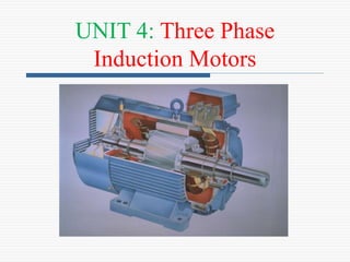
3. Construction of 3-Phase IM
An induction motor has two main
parts
- (a) stationary stator
• Consisting of a steel frame
that supports a hollow,
cylindrical core
• core, constructed from
stacked laminations, having
a number of evenly spaced
slots, providing the space for
the stator winding Stator of IM
4. Construction
(b) Revolving rotor
• composed of punched laminations, stacked to
create a series of rotor slots, providing space
for the rotor winding.
Two types of rotors:
Squirrel-Cage rotor: conducting bars laid into slots and shorted
at both ends by shorting rings (aluminum rings), forming a
squirrel-cage shaped circuit.
wound-rotor: Complete set of three-phase windings exactly as
the stator. Usually Y-connected, the ends of the three rotor wires
are connected to 3 slip rings on the rotor shaft. In this way, the
rotor circuit is accessible.
8. SCIM Vs SRIM
S.N
o
Squirrel Cage Induction
Motor
Slip Ring / Wound Rotor Induction
Motor
1 The rotor is simplest and most
rugged in construction.
The rotor is wound type and
construction is not simple.
2 Cylindrical laminated core rotor
with heavy bars or copper are
used for conductors.
Cylindrical laminated core rotor is
wound like winding on the stator.
3 Rotor conductors or rotor bars
are short circuited with end
rings.
At starting the 3 phase windings are
connected to a star connected rheostat
and during running, the windings are
short circuited at the slip rings.
4 Rotor bars are permanently
short circuited and hence it is
not possible to connect external
resistance in the circuit in series
with the rotor conductors.
It is possible to insert additional
resistance in the rotor circuit. Therefore
it is possible to increase the torque; the
additional series resistance is used for
starting purposes.
9. 5 Cheaper cost. Cost is slightly higher.
6 No moving contacts in the rotor. Carbon brushes, slip rings etc
are provided in the rotor
circuit.
7 Higher efficiency. Comparatively less efficiency.
8 Speed control by rotor resistance
is not possible.
Speed control by rotor
resistance is possible.
9 Starting current is 5 to 7 times
the full load current.
Less starting current
compared to squirrel cage
Induction Motor.
10. Rotating Magnetic Field in 3-Phase IM
Balanced three phase windings, i.e.
mechanically displaced 120 degrees
from each other, fed by balanced three
phase source.
A rotating magnetic field with constant
magnitude is produced, rotating with a
speed
Where fe is the supply frequency and
P is the no. of poles and nsync is called the
synchronous speed in rpm (revolutions
per minute)
120 e
sync
f
n rpm
P
11. Mathematical Proof:
Applied Currents in all the phases
Then flux will be produced in all the phases with
120 degree phase difference. Then the three mmfs are:
12. Rotating Magnetic Field
The resultant mmf is
Then the total mmf F
This shows that the resultant magnetic field is
rotating with synchronous speed.
13. Synchronous speed
P 50 Hz 60 Hz
2 3000 3600
4 1500 1800
6 1000 1200
8 750 900
10 600 720
12 500 600
120 e
sync
f
n rpm
P
14. Principle of operation
A 3-phase balanced AC supply is given to the 3-phase stator
winding, a rotating magnetic field will be developed;
This rotating magnetic field cuts the rotor windings and
produces an induced voltage in the rotor windings
Due to the fact that the rotor windings are short circuited, for
both squirrel cage and wound-rotor, and induced current
flows in the rotor windings
The rotor current produces another magnetic field
A torque is produced as a result of the interaction of those
two magnetic fields
Where ind is the induced torque and BR and BS are the magnetic
flux densities of the rotor and the stator respectively
ind R s
kB B
15. Induction motor speed
At what speed will the IM run?
- Can the IM run at the synchronous speed, why?
- If rotor runs at the synchronous speed, which is the
same speed of the rotating magnetic field, then the rotor
will appear stationary to the rotating magnetic field and
the rotating magnetic field will not cut the rotor. So, no
induced current will flow in the rotor and no rotor
magnetic flux will be produced so no torque is
generated and the rotor speed will fall below the
synchronous speed
- When the speed falls, the rotating magnetic field will
cut the rotor windings and a torque is produced
16. Induction motor speed
So, the IM will always run at a speed lower than
the synchronous speed
The difference between the motor speed and the
synchronous speed is called the Slip
Where nslip= slip speed
nsync= speed of the magnetic field
nm = mechanical shaft speed of the motor
slip sync m
n n n
17. The Slip
sync m
sync
n n
s
n
Where s is the slip
Notice that : if the rotor runs at synchronous speed
s = 0
if the rotor is stationary
s = 1
Slip may be expressed as a percentage by multiplying the above
eq. by 100, notice that the slip is a ratio and doesn’t have units
18. Induction Motors and Transformers
Both IM and transformer works on the principle of
Mutual Induction (induced voltage).
- Transformer: voltage applied to the primary windings
produce an induced voltage in the secondary windings
- Induction motor: voltage applied to the stator windings
produce an induced voltage in the rotor windings
- The difference is that, in the case of the induction motor,
the secondary windings can move.
- Due to the rotation of the rotor (the secondary winding
of the IM), the induced voltage in it does not have the
same frequency of the stator (the primary) voltage
19. Frequency
The frequency of the voltage induced in the rotor is
given by
Where fr = the rotor frequency (Hz)
P = number of stator poles
n = slip speed (rpm)
120
r
P n
f
( )
120
120
s m
r
s
e
P n n
f
P sn
sf
20. Frequency
What would be the frequency of the rotor’s induced
voltage at any speed nm?
When the rotor is blocked (s=1) , the frequency of
the induced voltage is equal to the supply frequency
On the other hand, if the rotor runs at synchronous
speed (s = 0), the frequency will be zero
r e
f s f
21. Torque
While the input to the induction motor is electrical
power, its output is mechanical power and for that we
should know some terms and quantities related to
mechanical power
Any mechanical load applied to the motor shaft will
introduce a Torque on the motor shaft. This torque is
related to the motor output power and the rotor speed
and
.
out
load
m
P
N m
2
/
60
m
m
n
rad s
22. Horse power
Another unit used to measure mechanical power is
the horse power
It is used to refer to the mechanical output power
of the motor
Since we, as an electrical engineers, deal with
watts as a unit to measure electrical power, there is
a relation between horse power and watts
746
hp watts
23. Example
A 208-V, 10hp, four pole, 60 Hz, Y-connected
induction motor has a full-load slip of 5 percent
1. What is the synchronous speed of this motor?
2. What is the rotor speed of this motor at rated load?
3. What is the rotor frequency of this motor at rated load?
4. What is the shaft torque of this motor at rated load?
24. Solution
1.
2.
3.
4.
120 120(60)
1800
4
e
sync
f
n rpm
P
(1 )
(1 0.05) 1800 1710
m s
n s n
rpm
0.05 60 3
r e
f sf Hz
2
60
10 746 /
41.7 .
1710 2 (1/ 60)
out out
load
m
m
P P
n
hp watt hp
N m
25. Equivalent Circuit
The induction motor is similar to the transformer with
the exception that its secondary windings are free to
rotate.
As we noticed in the transformer, it is easier if we can combine
these two circuits in one circuit but there are some difficulties
26. EMF induced in the Rotor
Where ER0 is the largest value of the rotor’s induced voltage
obtained at s = 1(locked rotor)
0
R R
E sE
27. The same is true for the frequency, i.e.
It is known that
So, as the frequency of the induced voltage in the
rotor changes, the reactance of the rotor circuit also
changes
Where Xr0 is the rotor reactance
at the supply frequency
(at blocked rotor)
r e
f s f
2
X L f L
0
2
2
r r r r r
e r
r
X L f L
sf L
sX
28. Then, we can draw the rotor equivalent circuit as
follows:
Where ER is the induced voltage in the rotor and RR is the
rotor resistance
29. Now we can calculate the rotor current as
Dividing both the numerator and denominator by s
so nothing changes, we get
Where ER0 is the induced voltage and XR0 is the rotor
reactance at blocked rotor condition (s = 1)
0
0
( )
( )
R
R
R R
R
R R
E
I
R jX
sE
R jsX
0
0
( )
R
R
R
R
E
I
R
jX
s
30. Now we can have the rotor equivalent circuit
31. Equivalent Circuit
Now as we managed to solve the induced voltage
and different frequency problems, we can combine
the stator and rotor circuits in one equivalent
circuit
Where
2
2 0
2
2
2
1 0
eff R
eff R
R
eff
eff R
S
eff
R
X a X
R a R
I
I
a
E a E
N
a
N
32. Power losses in Induction machines
Copper losses
- Copper loss in the stator (PSCL) = I1
2R1
- Copper loss in the rotor (PRCL) = I2
2R2
Core loss (Pcore)
Mechanical power loss due to friction and windage
How this power flow in the motor?
34. Power relations
3 cos 3 cos
in L L ph ph
P V I V I
2
1 1
3
SCL
P I R
( )
AG in SCL core
P P P P
2
2 2
3
RCL
P I R
conv AG RCL
P P P
( )
out conv f w stray
P P P P
conv
ind
m
P
35. Power relations
3 cos 3 cos
in L L ph ph
P V I V I
2
1 1
3
SCL
P I R
( )
AG in SCL core
P P P P
2
2 2
3
RCL
P I R
conv AG RCL
P P P
( )
out conv f w stray
P P P P
conv RCL
P P
2 2
2
3
R
I
s
2 2
2
(1 )
3
R s
I
s
RCL
P
s
(1 )
RCL
P s
s
(1 )
conv AG
P s P
conv
ind
m
P
(1 )
(1 )
AG
s
s P
s
37. Example
A 480-V, 60 Hz, 50-hp, three phase induction motor is
drawing 60A at 0.85 PF lagging. The stator copper
losses are 2 kW, and the rotor copper losses are
700 W. The friction and windage losses are 600 W,
the core losses are 1800 W, and the stray losses are
negligible. Find the following quantities:
1. The air-gap power PAG.
2. The power converted Pconv.
3. The output power Pout.
4. The efficiency of the motor.
38. Solution
1.
2.
3.
3 cos
3 480 60 0.85 42.4 kW
in L L
P V I
42.4 2 1.8 38.6 kW
AG in SCL core
P P P P
700
38.6 37.9 kW
1000
conv AG RCL
P P P
&
600
37.9 37.3 kW
1000
out conv F W
P P P
40. Example
A 460-V, 25-hp, 60 Hz, four-pole, Y-connected induction motor
has the following impedances in ohms per phase referred to
the stator circuit:
R1= 0.641 R2= 0.332
X1= 1.106 X2= 0.464 XM= 26.3
The total rotational losses are 1100 W and are assumed to be
constant. The core loss is lumped in with the rotational losses.
For a rotor slip of 2.2 percent at the rated voltage and rated
frequency, find the motor’s
1. Speed
2. Stator current
3. Power factor
4. Pconv and Pout
5. ind and load
6. Efficiency
41. Solution
1.
2.
120 120 60
1800 rpm
4
e
sync
f
n
P
(1 ) (1 0.022) 1800 1760 rpm
m sync
n s n
2
2 2
0.332
0.464
0.022
15.09 0.464 15.1 1.76
R
Z jX j
s
j
2
1 1
1/ 1/ 0.038 0.0662 1.76
1
12.94 31.1
0.0773 31.1
f
M
Z
jX Z j
42. Solution
3.
4.
0.641 1.106 12.94 31.1
11.72 7.79 14.07 33.6
tot stat f
Z Z Z
j
j
1
460 0
3 18.88 33.6 A
14.07 33.6
tot
V
I
Z
cos33.6 0.833 lagging
PF
3 cos 3 460 18.88 0.833 12530 W
in L L
P V I
2 2
1 1
3 3(18.88) 0.641 685 W
SCL
P I R
12530 685 11845 W
AG in SCL
P P P
43. Solution
5.
6.
(1 ) (1 0.022)(11845) 11585 W
conv AG
P s P
& 11585 1100 10485 W
10485
= 14.1hp
746
out conv F W
P P P
11845
62.8 N.m
1800
2
60
AG
ind
sync
P
10485
56.9 N.m
1760
2
60
out
load
m
P
10485
100% 100 83.7%
12530
out
in
P
P
45. The torque slip curve for an induction motor gives us
the information about the variation of torque with the
slip.
When the supply is given to the stator sides and the
motor always rotates below the synchronous speed.
The induction motor torque varies from zero to full load
torque as the slip varies. The slip varies from zero to one.
It is zero at no load and one at standstill. From the curve
it is seen that the torque is directly proportional to the
slip.
That is, more is the slip, more will be the torque
produced and vice-versa.
46. Starting Methods of an Induction Motor
A three phase Induction Motor is Self Starting.
When the supply is connected to the stator of a three-
phase induction motor, a rotating magnetic field is
produced, hence the rotor starts rotating and then the
induction motor starts.
At the time of starting, the motor slip is unity, and the
starting current is very large.
The purpose of a starter is not to just start the motor, but
it performs the two main functions. They are as follows.
47. There are three main methods of Starting of
Squirrel Cage Induction Motor.
They are as follows:
48. Direct Online Starter
The direct on line starter method, of an induction motor is
simple and economical.
In this method, the starter is connected directly to supply
voltage.
By this method small motors up to 5 kW rating is started
to avoid the supply voltage fluctuation.
49. Star-Delta Starter
The Star-Delta Starter is a very
common type of starter and is used
extensively as compared to the
other type of starting methods of
the induction motor.
When the switch S is in the
START position, the stator
windings are connected in the star
as shown in Fig.
50. When the motor picks up the speed, about 80 percent of
its rated speed, the switch S is immediately put into the
RUN position.
As a result, a stator winding which was in star connection
is changed into DELTA connection now as shown in the
fig.
At the time of starting ( Star connection)
Under Running condition(Delta)
52. Auto transformer Starter
An Auto transformer
Starter is suitable for
both star and delta
connected motors.
In this method, the
starting current is
limited by using a
three-phase auto
transformer to reduce
the initial stator
applied voltage.
53. The primary of the auto transformer is connected to the
supply line, and the motor is connected to the
secondary of the auto transformer.
When the motor picks up the speed of about 80 percent
of its rated value, the handle H is quickly moved to the
RUN position.
Thus, the auto transformer is dis-connected from the
circuit, and the motor is directly connected to the line
and achieve its full rated voltage.
where K is the transformation ratio.
The star delta starter is equivalent to an auto
transformer starter of the ratio K =1/3= 0.58.
54. Starting method of Slip Ring Induction Motor
In the Slip Ring Induction Motor starter, the full
supply voltage is connected across the starter. The
connection diagram of the slip ring induction motor
starter is shown below.
55. Full starting resistance is connected and thus the supply
current to the stator is reduced.
The rotor begins to rotate, and the rotor resistances are
gradually cut out as the speed of the motor increases.
When the motor is running at its rated full load speed,
the starting resistances are cut out completely, and the
slip rings are short-circuited.
In this way we can start the 3-Phase IM safely.
56. BRAKE TEST ON A THREE PHASE
SLIP RING INDUCTION MOTOR
Aim : To conduct the load test on a three phase slip ring
Induction motor and to draw the performance and
mechanical characteristics, i.e.(i) Efficiency Vs. Output
power, (ii) Torque Vs.Output power, (iii) Line current Vs.
Output power, (iv) Power factor Vs. Output, (v) Slip Vs.
Output power, and (vi) Torque Vs. Speed
58. Procedure:
1- Connect the circuit as per fig.
2- Ensure that the motor is unloaded and the variac of
autotransformer is set at zero output
voltage.
3- Switch-ON 3 phase AC mains and start the motor at
reduced applied voltage.
4- Increase the applied voltage, till its rated value.
5- Take-down the readings of all the meters and the speed
under no load running in table.
60. 6- Increase the load on the motor gradually by turning
of the hand wheels, thus tighten the belt.
7- Record the readings of all the meters and the speed at
every setting of the load in above table.
8- Observation may be continued upto the full load
current rating of the motor.
9- Reduce the load on the motor and finally unload it
completely.
10- Switch-OFF the supply to stop the motor.
11- Measure the radius of the pulley (R) in (meter).