Downloaded 154 times

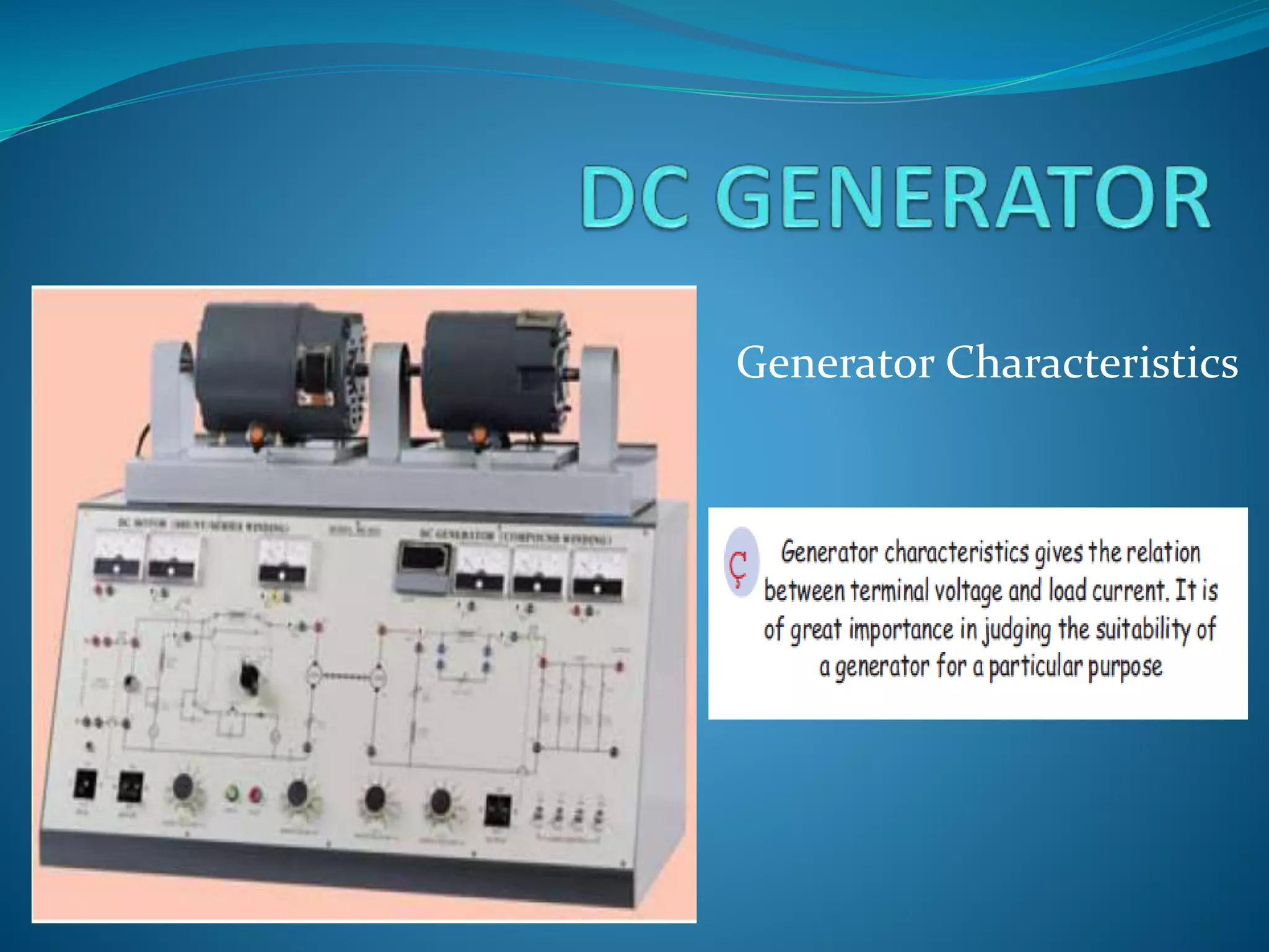
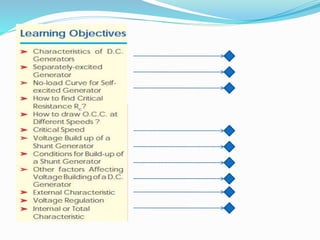
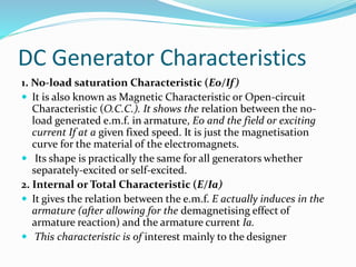

Here are the answers to the questions on DC generator characteristics: 1. The external characteristic gives the relation between terminal voltage and load current. 2. The three most important characteristics or curves of a DC generator are: the no-load saturation characteristic (E0/If), internal or total characteristic (E/Ia), and external characteristic (V/I). 3. Critical speed of a shunt generator means the speed for which the given shunt field resistance represents critical resistance. 4. One condition necessary for the build-up of a self-excited shunt generator is that there must be some residual magnetism in the generator poles. 5. Some other factors which affect the voltage building of