This document discusses electrical current, current density, resistivity, resistance, and circuit analysis using Kirchhoff's laws. It provides examples of calculating current, resistance, voltage, and power in series, parallel, and combination circuits. Key points covered include:
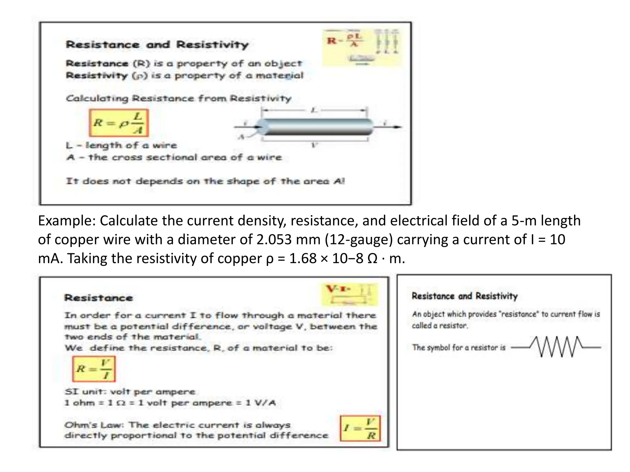
- Definitions of current, current density, resistivity, resistance, and their units
- Relationships between current density, current, area, and resistance
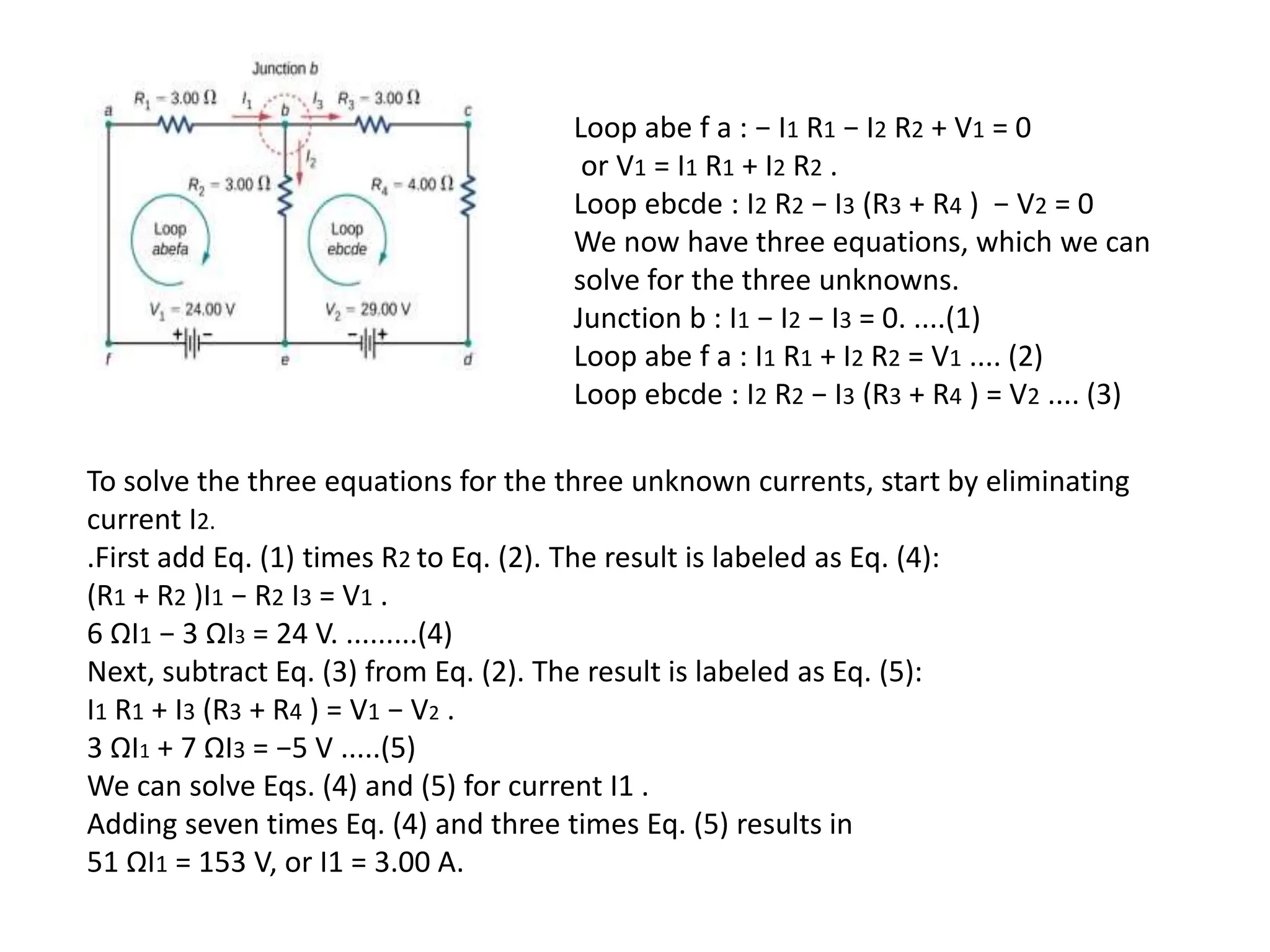
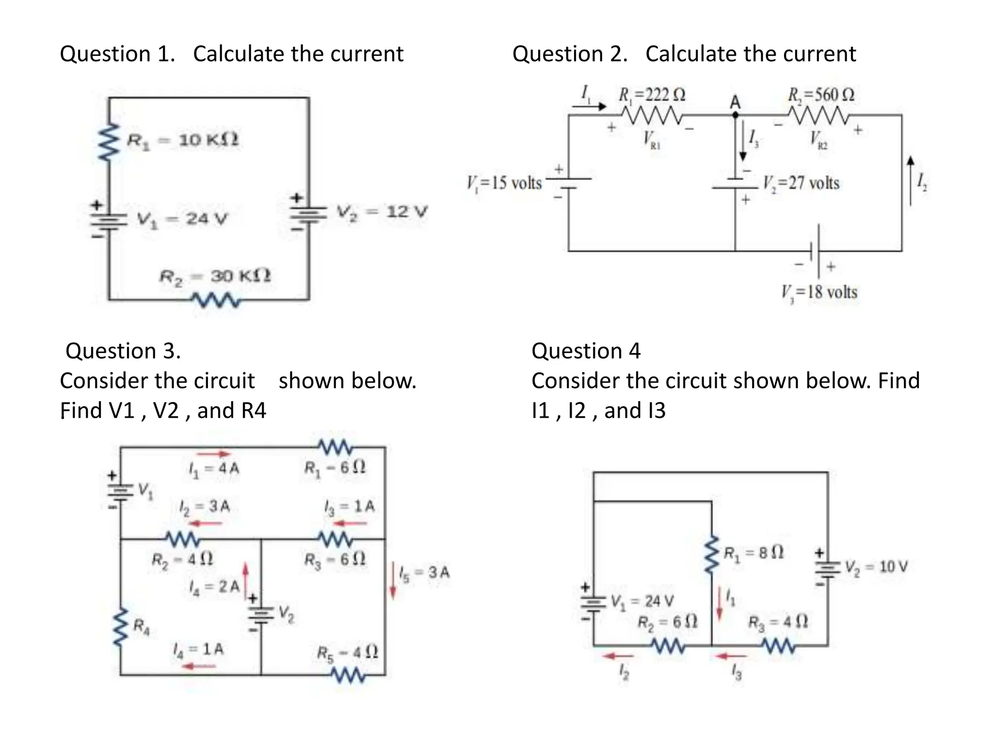
- Kirchhoff's junction and loop rules for analyzing circuits
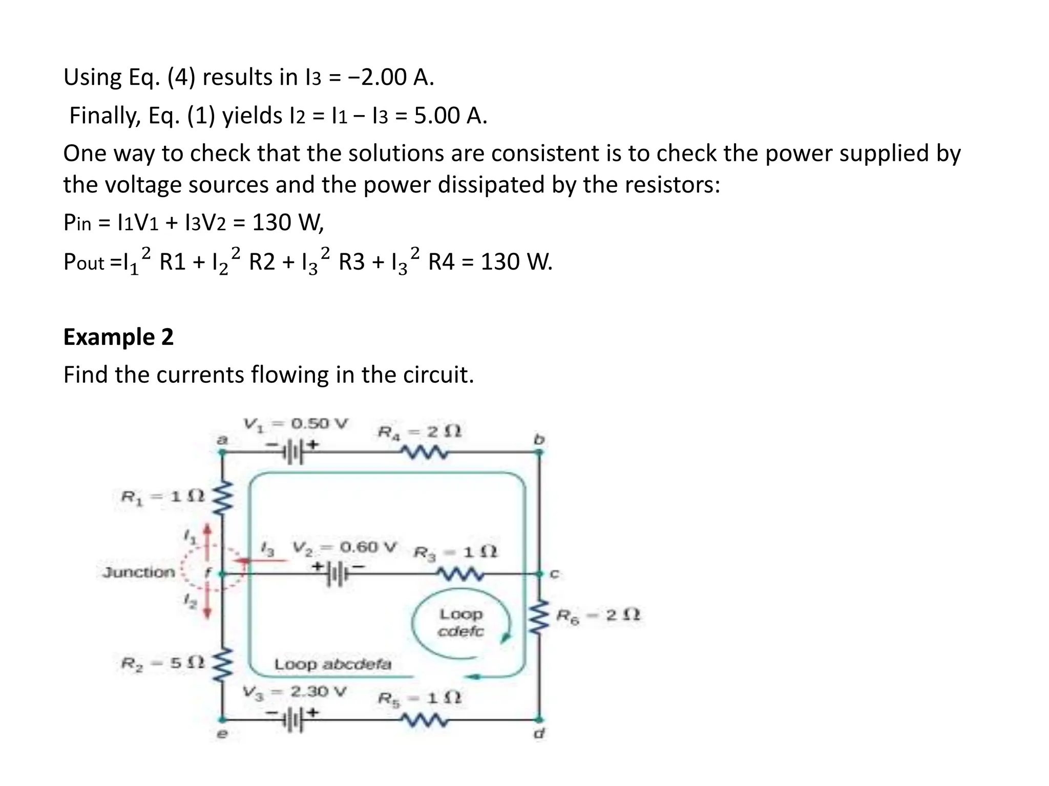
- Examples of using the junction and loop rules to solve for unknown currents, voltages, and resistances in various circuits.