Download as PDF, PPTX

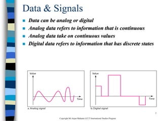
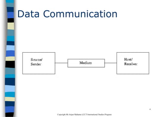
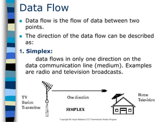
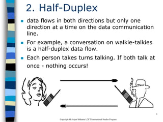
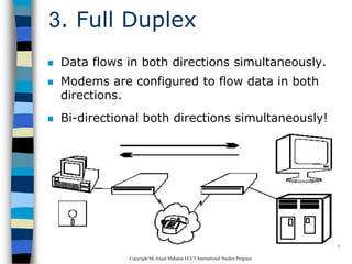
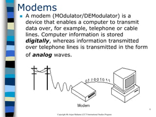
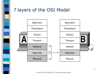
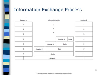
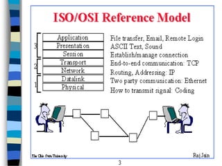
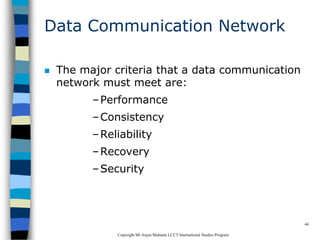


This document provides an introduction to data communication and networking. It discusses analog and digital data, data communication, data flow including simplex, half-duplex and full-duplex, and modems. It also covers local area networks, metropolitan area networks, wide area networks, network topologies including linear bus, star, tree and others. Finally, it discusses the OSI model and considerations for data communication networks including performance, consistency, reliability and recovery.