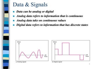
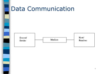
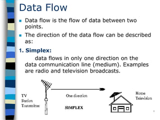
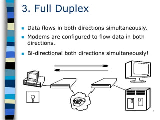
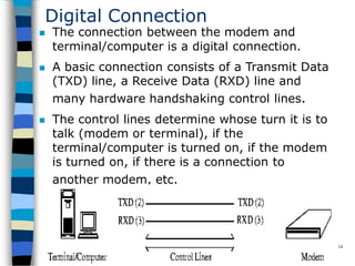
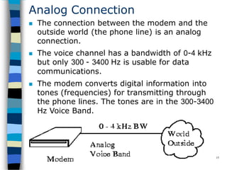
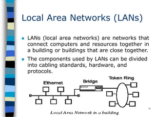
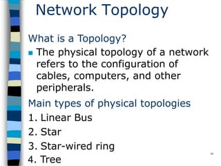
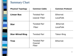
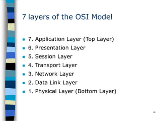
SlideShare a Scribd company logo
1
Introduction to Data
Communication & Networking
Data & Signals
 Data can be analog or digital
 Analog data refers to information that is continuous
 Analog data take on continuous values
 Digital data refers to information that has discrete states
2
Data Communication
3
 Data Communications is the transfer of data or
information between a source and a receiver.
 The source transmits the data and the receiver
receives it.
 The purpose of data communications is to
provide the rules and regulations that allow
computers with different disk operating systems,
languages, cabling and locations to share
resources.
 The rules and regulations are called protocols
and standards in data communications.
Data Communication
4
Data Flow
 Data flow is the flow of data between two
points.
 The direction of the data flow can be described
as:
1. Simplex:
data flows in only one direction on the
data communication line (medium). Examples
are radio and television broadcasts.
5
2. Half-Duplex
 data flows in both directions but only one
direction at a time on the data communication
line.
 For example, a conversation on walkie-talkies
is a half-duplex data flow.
 Each person takes turns talking. If both talk at
once - nothing occurs!
6
3. Full Duplex
 Data flows in both directions simultaneously.
 Modems are configured to flow data in both
directions.
 Bi-directional both directions simultaneously!
7
Modems
 A modem (MOdulator/DEModulator) is a
device that enables a computer to transmit
data over, for example, telephone or cable
lines. Computer information is stored
digitally, whereas information transmitted
over telephone lines is transmitted in the form
of analog waves.
8
9
How fast the modem can
transmit and receive data?
 At slow rates, modems are measured in terms
of baud rates
 The slowest rate is 300 baud
 At higher speeds, modems are measured in
terms of bits per second (bps)
 The fastest modems run at 57,600 bps
 The faster the transmission rate, the faster
you can send and receive data
 For example, if the device sending data to
your computer is sending it at 2,400 bps, you
must receive it at 2,400 bps
About Voice/Data
10
 Many modems support a switch to change
between voice and data modes
 In data mode, the modem acts like a regular
modem
 In voice mode, the modem acts like a regular
telephone
 Modems that support a voice/data switch have
a built-in loudspeaker and microphone for
voice communication
Auto-answer modem
11
 An auto-answer modem enables your
computer to receive calls in your
absence.
Data Compression modem
12
 Some modems perform data compression,
which enables them to send data at faster
rates
 However, the modem at the receiving end
must be able to decompress the data using
the same compression technique.
Fax Capability modem
13
 Most modern modems are fax modems, which
means that they can send and receive faxes.
Digital Connection
 The connection between the modem and
terminal/computer is a digital connection.
 A basic connection consists of a Transmit Data
(TXD) line, a Receive Data (RXD) line and
many hardware handshaking control lines.
 The control lines determine whose turn it is to
talk (modem or terminal), if the
terminal/computer is turned on, if the modem
is turned on, if there is a connection to
another modem, etc.
14
Analog Connection
 The connection between the modem and the
outside world (the phone line) is an analog
connection.
 The voice channel has a bandwidth of 0-4 kHz
but only 300 - 3400 Hz is usable for data
communications.
 The modem converts digital information into
tones (frequencies) for transmitting through
the phone lines. The tones are in the 300-3400
Hz Voice Band.
15
Types of Modems
16
 External Modem
– External modems sit next to the computer
and connect to the serial port using a
straight-through serial cable.
 Internal Modem
– An internal modems is a plug-in circuit
board that sits inside the computer. It
incorporates the serial port on-board.
– They are less expensive than external
modems because they do not require a
case, power supply and serial cable.
Telecommunications
17
 Telephones and networking work hand in hand.
 The common goal is to join distantly located
Local Area Networks into Metropolitan and Wide
Area Networks (MANs and WANs).
 Talking to someone on the phone uses voice
channels.
 We use voice channels for modem
communications to connect to the Internet.
 Due to the bandwidth limits on voice channels,
the data transfer rate is relatively slow.
Voice Channels
18
 Voice Channel: Dial-up connection through a
modem using standard telephone lines.
 Typical voice channel communication rates
are: 300, 1200, 2400, 9600, 14.4k, 19.2k, 28.8k,
33.6k and 56 kbps (bits per second).
Data Channels
19
 Data channels are dedicated lines for
communicating digitized voice and data.
 At the end of 1996, there was a major milestone
when more data was communicated in North
America's telecommunications system than
voice.
 Data Channels are special communications
channels provided by "common carriers" such as
Telus, Sprint, Bell Canada, AT&T, etc. for
transferring digital data.
 Data Channels are also called "Leased Lines".
Data Channels(Contd.)
20
 They are "directly" connected: you don't have
to dial a connection number.
 The connections are up and running 24 hours
per day.
 They appear to work as if there were a wire
running directly between the source and the
destination.
 Typical transfer rates for data channels are: 56
k, 128k, 1.544 M, 2.08 M, 45M and 155 Mbps.
Data Channels(Contd.)
21
 Common carriers charge for data
connections by:
–The amount of data transferred
(megabytes per month)
–The transfer rate (bits per second)
–The amount of use (time per month)
What is a network?
22
 A network can consist of two computers
connected together on a desk or it can consist
of many Local Area Networks (LANs)
connected together to form a Wide Area
Network (WAN) across a continent.
 The key is that two or more computers are
connected together by a medium and are
sharing resource.
 These resources can be files, printers,
hard•drives, or CPU number-crunching power.
23
Breaking the big picture
24
 Local loops
 LANs
 MANs
 WANs
Local loops
 The Local Loop is often called "the last mile"
 It refers to the last mile of analog phone line
that goes from the telephone company's
central office (CO) to your house.
25
Local Area Networks (LANs)
 LANs (local area networks) are networks that
connect computers and resources together in
a building or buildings that are close together.
 The components used by LANs can be divided
into cabling standards, hardware, and
protocols.
26
Metropolitan Area Networks(MANs)
 Metropolitan Area Networks (MANs) are
networks that connect LANs together within a
city.
 The main criterion for a MAN is that the
connection between LANs is through a local
exchange carrier (the local phone company).
27
Wide Area Networks(WANs)
 Wide Area Networks (WANs) connect LANs
together between cities.
 The main difference between a MAN and a
WAN is that the WAN uses Long Distance
Carriers. Otherwise the same protocols and
equipment are used as a MAN.
28
29
Network Topology
What is a Topology?
 The physical topology of a network
refers to the configuration of
cables, computers, and other
peripherals.
Main types of physical topologies
1. Linear Bus
2. Star
3. Star-wired ring
4. Tree
30
Linear Bus
 A linear bus topology consists of a main
run of cable with a terminator at each
end (See figure). All nodes (file server,
workstations, and peripherals) are
connected to the linear cable. Ethernet
and local talk networks use a linear bus
topology.
Advantages of linear bus
 Easy to connect a computer or peripheral to a
linear bus.
 Requires less cable length than a star
topology.
Disadvantages of linear bus
 Entire network shuts down if there is a break
in the main cable.
 Terminators are required at both ends of the
backbone cable.
 Difficult to identify the problem if the entire
network shuts down.
 Not meant to be used as a stand-alone
solution in a Largebuilding
31
Linear Bus
32
Star
 A star topology is designed with each node
(file server, workstations, and peripherals)
connected directly to a central network hub or
concentrator (See figure).
 Data on a star network passes through the
hub or concentrator before continuing to its
destination.
33
Star
Advantages of star
 Easy to install and wire.
 No disruptions to the network then connecting
or removing devices.
 Easy to detect faults and to remove parts.
Disadvantages of star
 Requires more cable length than a linear
topology.
 If the hub or concentrator fails, nodes
attached are disabled.
 More expensive than linear bus topologies
because of the cost of the concentrators.
Star-Wired Ring
34
 A star-wired ring topology may appear
(externally) to be the same as a star topology.
 Internally, the MAU (multistation access unit)
of a star-wired ring contains wiring that allows
information to pass from one device to
another in a circle or ring
Tree
 A tree topology combines characteristics of linear bus
and star topologies.
 It consists of groups of star-configured workstations
connected to a linear bus backbone cable
 Tree topologies allow for the expansion of an existing
network, and enable schools to configure a network to
meet their needs.
35
Tree
36
 Advantages
– Point-to-point wiring for individual segments.
– Supported by several hardware and software
vendors.
 Disadvantages
– Overall length of each segment is limited by the type
of cabling used.
– If the backbone line breaks, the entire segment goes
down.
– More difficult to configure and wire than other
topologies.
Considerations When Choosing a Topology:
37
 Money. A linear bus network may be the least
expensive way to install a network; you do not
have to purchase concentrators.
 Length of cable needed. The linear bus
network uses shorter lengths of cable.
 Future growth. With a star topology,
expanding a network is easily done by adding
another concentrator.
 Cable type. The most common cable in
schools is unshielded twisted pair, which is
most often used with star topologies.
SummaryChart
38
Physical Topology Common Cable Common Protocol
Linear Bus Twisted Pair
coaxial Fiber
Ethernet
LocalTalk
Star Twisted Pair
Fiber
Ethernet
LocalTalk
Star-Wired Ring Twisted Pair Token Ring
Tree Twisted Pair
Coaxial
Fiber
Ethernet
Introduction to the ISO - OSI Model
39
 The ISO (International Standards
Organization) has created a layered model,
called the OSI (Open Systems Interconnect)
model.
 The purpose of the layers is to provide clearly
defined functions that can improve
Internetwork connectivity between
"computer" manufacturing companies.
 Each layer has a standard defined input and a
standard defined output.
7 layers of the OSI Model
40
 7. Application Layer (Top Layer)
 6. Presentation Layer
 5. Session Layer
 4. Transport Layer
 3. Network Layer
 2. Data Link Layer
 1. Physical Layer (Bottom Layer)
7 layers of the OSI Model
41
Information Exchange Process
42
43
Data Communication Network
44
 The major criteria that a data communication
network must meet are:
–Performance
–Consistency
–Reliability
–Recovery
–Security
Performance
45
– Software program
 Performance is the defined as the rate of
transference of error-free data.
 It is measured by the response time.
 Response time is the elapsed time between
the end of an inquiry and the beginning of a
response
– Example requesting a file transfer and starting the
file transfer.
 Factors that affect response time are:
– Number of Users:
– Transmission Speed:
– Hardware Type:
Consistency
46
 Consistency is the predictability of response
time and accuracy of data.
– For example, if the "normal" response time is 3
seconds for printing to a network printer but a
response time of over 30 seconds occurs, we know
that there is a problem in the system!
Reliability
47
 Reliability is the measure of how often a
network is usable.
 MTBF (Mean Time Between Failures) is a
measure of the average time a component is
expected to operate between failures, and is
normally provided by the manufacturer.
 A network failure can be caused by a problem
with the hardware, the data carrying medium,
or the Network Operating System.
Recovery
48
 Recovery is the network's ability to return to a
prescribed level of operation after a network
failure.
 This level is where the amount of lost data is
nonexistent or at a minimum. Recovery is
based on having back-up files.
Security
49
 Security is the protection of hardware,
software and data from unauthorized access.
 Restricted physical access to computers,
password protection, limiting user privileges
and data encryption are common security
methods.
 Anti-virus monitoring programs to defend
against computer viruses are also a security
measure.
Application
50
 Electronic Mail (e-mail or Email)
 Teleconferencing allows people in different
regions to "attend" meetings using telephone
lines.
 Automated Banking Machines allow banking
transactions to be performed everywhere
 Groupware is the latest network application. It
allows user groups to share documents,
schedules databases, etc. (ex. Lotus Notes)
Physical Connection
51
 The physical connection determines how many
bits (1's or 0's) can be transmitted in a single
instance of time.
 If only 1 bit of information can be transmitted
over the data transmission medium at a time
then it is considered a serial communication.
 If more than 1 bit of information is transmitted
over the data transmission medium at a time
then it is considered a parallel communication.
52
Communications
53
Advantages
 Parallel : faster
transfer rates
 Serial : long
distances
Disadvantages
 Parallel: short
distance only
 Serial : slow transfer
rates
Transmission Media- Guided
54
There are 2 basic categories of transmission
media: guided and unguided.
 Guided transmission media uses a cabling
system that guides the data signals along a
specific path.
 Unguided transmission media consists of a
means for the data signals to travel but
nothing to guide them along a specific path.
Transmission Media- Guided
55
There 4 basic types of guided media:
 Open Wire
 Twisted Pair
 Coaxial Cable
 Optical Fiber
Open wire
 Open wire is traditionally used to describe the
electrical wire strung along power poles.
 There is a single wire strung between poles.
 No shielding or protection from noise
interference is used.
56
Twisted Pair
 The wires in twisted pair cabling are twisted
together in pairs.
 Each pair consists of a wire used for the +ve
data signal and a wire used for the -ve data
signal.
 Any noise that appears on 1 wire of the pair
will also occur on the other wire.
 When the noise appears on both wires, it
cancels or nulls itself out at the receiving end.
57
Unshielded Twisted Pair
 The degree of reduction in noise interference is
determined specifically by the number of turns per foot.
 Increasing the number of turns per foot reduces the
noise interference.
 To further improve noise rejection, a foil or wire braid
"shield" is woven around the twisted pairs.
 Cables with a shield are called shielded twisted pair and
are commonly abbreviated STP.
 Cables without a shield are called unshielded twisted
pair or UTP.
58
Coaxial cable
 Coaxial cable consists of two conductors.
 The inner conductor is held inside an insulator
with the other conductor woven around it
providing a shield.
 An insulating protective coating called a jacket
covers the outer conductor.
59
Coaxial cable
60
 The outer shield protects the inner conductor
from outside electrical signals.
 The distance between the outer conductor
(shield) and inner conductor plus the type of
material used for insulating the inner
conductor determine the cable properties or
impedance.
 Typical impedances for coaxial cables are 75
ohms for Cable TV, 50 ohms for Ethernet
Thinnet and Thicknet.
Optical fiber
 Optical fiber consists of thin glass fibers that can carry
information at frequencies in the visible light spectrum
and beyond.
 The typical optical fiber consists of a very narrow strand
of glass called the core.
 Around the core is a concentric layer of glass called the
cladding.
 Coating the cladding is a protective coating consisting of
plastic, it is called the Jacket.
61
Optical fiber
 An important characteristic of fiber optics is refraction.
 Refraction is the characteristic of a material to either
pass or reflect light.
 When light passes through a medium, it "bends" as it
passes from one medium to the other.
 An example of this is when we look into a pond of
water.
62
Optical fiber
 If the angle of incidence is small, the light rays
are reflected and do not pass into the water.
 If the angle of incident is great, light passes
through the media but is bent or refracted.
63
Advantages of Optical fiber
64
 Noise immunity: RFI and EMI immune
(RFI - Radio Frequency Interference,
EMI -Electromagnetic Interference)
 Security: cannot tap into cable.
 Large Capacity due to BW (bandwidth)
 No corrosion (destroy metal)
 Longer distances than copper wire
 Smaller and lighter than copper wire
 Faster transmission rate
Disadvantages of Optical fiber
65
 Physical vibration will show up as signal
noise!
 Limited physical arc of cable. Bend it
too much and it will break!
 Difficult to splice (to join)
Comparison
66
 The following compares the usable bandwidth
of the different guided transmission media.
Cable Type
Open Cable
Twisted Pair
Coaxial Cable
Optical Fiber
Bandwidth
0 - 5 MHz
0 - 100 MHz
0 - 600 MHz
0 - 1 GHz
Transmission Media - Unguided
67
 Unguided transmission media is data signals
that flow through the air.
 They are not guided or bound to a channel to
follow.
 They are classified by the type of wave
propagation.
– RF (Radio Frequency) Propagation
– Microwave Propagation
– Satellite Propagation
RF Propagation
68
 There are three types of RF (radio frequency)
propagation:
1.Ground Wave
2.Ionospheric
3.Line of Sight (LOS)
Groundwave propagation
 Ground wave propagation follows the
curvature of the Earth.
 Ground waves have carrier frequencies up to 2
MHz. AM Radio is an example of ground wave
propagation.
69
CopyrightMr.AnjanMahanta LCCTInternational Studies Program
Ionospheric propagation
 Ionospheric propagation bounces off of the
Earth's ionospheric layer in the upper
atmosphere.
 It operates in the frequency range of 30 - 85
MHz.
 Because it depends on the Earth's ionosphere,
it changes with the weather and time of day.
 Ham radios operate in this range.
70
Line of sight propagation
 Line of sight propagation transmits exactly in
the line of sight.
 The receive station must be in the view of the
transmit station.
 It is limited by the curvature of the Earth for
ground-based stations (100 km, from horizon
to horizon).
 Examples of line of sight propagation are: FM
radio, microwave and satellite.
71
Microwave
 Microwave transmission is line of sight
transmission.
 The transmit station must be in visible contact
with the receive station.
 Typically the line of sight due to the Earth's
curvature is only 50 km to the horizon!
Repeater stations must be placed so the data
signal can hop, skip and jump across the
country.
72
Microwave
73
 Microwaves operate at high operating
frequencies of 3 to 10 GHz.
 This allows them to carry large quantities of
data due to their large bandwidth.
 Advantages:
– They can carry high quantities of information due to
their high operating frequencies.
– Low cost land purchase: each tower occupies only a
small area.
– High frequency/short wavelength signals require
small antennae.
Microwave
74
 Disadvantages
– Attenuation by solid objects: birds, rain, snow and
fog.
– Reflected from flat surfaces like water and metal.
– Diffracted (split) around solid objects.
– Refracted by atmosphere, thus causing beam to be
projected away from receiver.
Satellite
 Satellites are transponders (units that receive
on one frequency and retransmit on another)
that are set in geostationary orbits directly
over the equator.
75
Satellite
 These geostationary orbits are 36,000 km from
the Earth's surface.
 At this point, the gravitational pull of the Earth
and the centrifugal force of Earth's rotation
are balanced and cancel each other out.
76
Satellite
77
 The uplink is the transmitter of data to the
satellite.
 The downlink is the receiver of data.
 Uplinks and downlinks are also called Earth
stations because they are located on the
Earth.
 The footprint is the "shadow" that the satellite
can transmit to, the shadow being the area
that can receive the satellite's transmitted
signal.
Networking Devices
78
 Repeaters:Repeaters are physical hardware devices:
they have a primary function to regenerate the
electrical signal
 The purpose of a repeater is to extend the LAN Segment
beyond its physical limits
 Typically, repeaters are used to connect two physically
close buildings together (when they are too far apart to
just extend the segment).
 They can be used to connect floors of a building that
would normally surpass the maximum allowable
segment length.
 For large extensions two Repeaters are required but for
shorter extensions, only one Repeater may be required.
Networking Devices
 Repeaters:
79
Networking Devices
 Repeaters operate at the OSI Model
80
Networking Devices
 Multiport Repeaters
81
Networking Devices
 Hubs:Hubs are used to provide a Physical Star
Topology.
 At the center of the star is the Hub, with the
network nodes located on the tips of the star.
 The Hub is installed in a central wiring closet,
with all the cables extending out to the
network nodes.
82
Networking Devices
 Hubs:
83
Networking Devices
 Bridges: Bridges are both hardware and software devices.
84
Networking Devices
85
 Purpose of a Bridge
 The purposes of a Bridge are the
following:
– Isolates networks by MAC addresses
– Manages network traffic by filtering
packets
– Translates from one protocol to
another
Networking Devices
 Isolates networks by MAC addresses
86
Networking Devices
87
Manages network traffic by filtering packets
 Bridges listen to the network traffic, and build
an image of the network on each side of the
bridge.
 This image of the network indicates the
location of each node
 With this information, a bridge can make a
decision whether to forward the packet across
the bridge
 This process of deciding whether or not to
forward a packet is termed "filtering packets."
Networking Devices
88
Translates from one protocol to another
 Bridges are store and forward devices.
 They receive a packet on the local segment,
store it, and wait for the remote segments to
be clear before forwarding the packet.
Networking Devices
Reasons to use a Bridge
 Bandwidth: Reduce traffic by segmentation
 Reliability: If 1 segment goes down, it does
not take down the complete LAN
 Translation: Translate different Data Link
protocols
89
Networking Devices
90
 Gateways
 A Gateway is the Hardware/Software device
that is used to interconnect LANs & WANs
using mainframe computers
 Example: DECnet and IBM's SNA
 Often, the router that is used to connect a LAN
to the Internet will be called a gateway.
 It will have added capability to direct and filter
higher layer protocols (layer 4 and up) to
specific devices (such as web servers, ftp
servers and e-mail servers).
Protocol IEEE-802.3
91
 The IEEE-802.3 Protocol is based on the Xerox
Network Standard (XNS) called Ethernet
 These are the four versions of the Ethernet
frame
– Ethernet_802.2
– Ethernet_802.3
– Ethernet_II
– Ethernet_SNAP
 NOTE: The Source and Destination must have
the same Ethernet Frame type in order to
communicate.
Protocol IEEE-802.3
92
 IEEE 802.3 defines five media types of
IEEE 802.3 Ethernet Types shown
below:
1. IEEE 802.3 - 10Base5 (Thick Coax) is used
only as backbones to networks. Backbones are
lines that connect buildings & network
equipment together (such as Bridges, Routers,
Hubs, Concentrators, Gateways, etc.).
10Base5 is now being replaced by either Thin
Coax or fiber optics.
Protocol IEEE-802.3
93
2.IEEE 802.3a - 10Base2 is commonly used
in new installations as a backbone to
connect buildings and network equipment
together.
10Base2 (Thin Coax) is also used to connect
work stations together, but the preferred
choice is to use 10BaseT.
3.IEEE 802.3b - 10Broad36 is rarely used; it
combines analog and digital signals together.
Broadband means that a mixture of signals
can be sent on the same medium.
Protocol IEEE-802.3
94
4.IEEE 802.3e - 1 Base 5 StarLAN is a slow 1
Mbps standard that has been replaced by Thin
Coax or Twisted Pair.
5.IEEE 802.3i - 10BaseT is commonly used to
connect workstations to network hubs.
The network hubs can use 10BaseT (Twisted
Pair) to connect to other Hubs.
10 Base T (Twisted Pair Cable)
95
 10BaseT uses unshielded twisted pair (UTP)
cable.
 The cable is flexible and easy to work with.
 The cable has a characteristic impedance of
100 ohms.
 There are 2 pairs of twisted wires used with
10BaseT: separate Rx (receive) and Tx
(transmit) pairs.
 The lines are balanced lines to minimize noise
and there are a Rx+ & Rx- pair and a Tx+ &
Tx- pair.
10 Base T (Twisted Pair Cable)
96
 The nodes are connected to a MPR (multi port
repeater), also called a Concentrator, or Hub.
 Maximum Nodes
 For 10BaseT, the maximum allowed number of
nodes is 128 (on one segment).
 Maximum Distance between Nodes & Hub
 The maximum distance between nodes & Hub
is 100 m.
Cable Termination and Connector
 The standard termination is 100 ohms.
 The end connector is an "RJ45" quick
disconnect connector.
 The cable is internally terminated at the NIC
(Network Interface Card) and Hub.
97
TCP/IP Protocols
98
TCP/IP Protocols
99
 Network Devices are network interface
cards (NIC) and their software drivers.
 Typically, they are Ethernet cards,
Token Ring cards, and WAN links (such
as ISDN or Frame Relay), and they can
also be modems and serial ports.
 IP stands for Internet Protocol. Its main
job is to find the best route--through
the Internet--to the destination.
 IP uses IP addresses to identify the host
machine and the network.
TCP/IP Protocols
100
 A typical IP address is a 32 bit number, and
looks like 142.110.237.1.
 In this case, 142.110.237.0 identifies the
network address, and 0.0.0.1 identifies the host
machine.
 ARP stands for Address Resolution Protocol
and it is used to map IP addresses to MAC
addresses.
 ICMP stands for Internet Control Message
Protocol, and is used mainly for
troubleshooting TCP/IP network connections.
TCP/IP Protocols
101
 TCP stands for Transmission Control Protocol,
and is used to guarantee end to end delivery
of segments of data.
 TCP is used to put out of order segments in
order, and to check for transmission errors.
 UDP stands for User Datagram Protocol, and is
a connectionless service.
 This results in a low overhead and fast transfer
service (relies on the upper layer protocols to
provide error checking and delivery of data).
 In the Application layer lies many hundreds of network-
aware programs and services such as the following:
 HTTP (80) - Hyper Text Transport Protocol, which is used
for transferring web pages.
 SNMP (161/162)- Simple Network Management Protocol,
which is used for managing network devices.
 FTP (20/21)- File Transfer Protocol, which is used for
transferring files across the network.
 TFTP (69)- Trivial File Transfer Protocol, which is a low
overhead fast transfer FTP protocol.
 SMTP (25)- Simple Mail Tranfer Protocol, which is used
for transferring email across the Internet.
 Telnet (23)- An application for remotely logging into a
server across the network.
 NNTP (119)- Network News Transfer Protocol, which is
used for transferring news.
* The numbers, shown in brackets next to the protocols, are called the
102
Wireless Network
103
CopyrightMr.AnjanMahanta LCCTInternational Studies Program
 What is wireless networking?
 A wireless network is simply two or
more computers (and maybe printers)
linked by radio waves.
 There are various other devices that
can connect to this wireless network.
 This arrangement uses a protocol
(method of communication) called, IEEE
802.11b, or Wi-Fi
Range & Performance
104
 Wi-Fi is currently the fastest wireless
technology.
 It can transmit through walls and floors at
speeds of up to 11 Mbps.
 Bandwidths available:-
 11Mbps
 22Mbps
 54Mbps
 Super G 108Mbps
Wireless adapters
 Wireless network adapters can be internal (inserted in a
computer) or external (housed in a separate case).
 The two general types of wireless adapters are:
 USB adapter: Connects through a USB cable to a USB
port on your desktop computer. USB adapters are
popular because they are easy to install and to swap
between desktop computers as necessary.
 Notebook adapter: Fits into the PCMCIA slot on your
laptop or other portable computer. Notebook adapters
eliminate the need for cable connections to the
computer and are popular among users who value
mobility.
105
Benefits of wireless network
106
 Convenience: You can set up wireless
connections without having to run cables or
open computer cases.
 Mobility: Mobility might be relatively
unimportant for a desktop computer but can
be an important benefit if you have a laptop or
notebook computer.
Bandwidth Case I
bandwidthinbitspersecond,referstothespeedofbittransmissioninachannelorlink
107
Bandwidth Case II
108

More Related Content

Similar to datacommunicationnetworking-161025074805.pptx

Computer Network - Unit 1
Computer Network - Unit 1Computer Network - Unit 1
Computer Network - Unit 1
Chandan Gupta Bhagat
 
Networking Fundamentals
Networking FundamentalsNetworking Fundamentals
Networking Fundamentals
DURYODHAN MAHAPATRA
 
Computer Networking
Computer NetworkingComputer Networking
Computer Networking
Alisha Jain
 
Transmission Media।।Circuit Switching।।Telephone Network।।DSL।।Cable Modems।।...
Transmission Media।।Circuit Switching।।Telephone Network।।DSL।।Cable Modems।।...Transmission Media।।Circuit Switching।।Telephone Network।।DSL।।Cable Modems।।...
Transmission Media।।Circuit Switching।।Telephone Network।।DSL।।Cable Modems।।...
sabbirantor
 
final NEtworking.pptx
final  NEtworking.pptxfinal  NEtworking.pptx
final NEtworking.pptx
HardeepKaurCSEAssist
 
LAN_ROHIT_KUMAR_SHAH.pptx
LAN_ROHIT_KUMAR_SHAH.pptxLAN_ROHIT_KUMAR_SHAH.pptx
LAN_ROHIT_KUMAR_SHAH.pptx
RohitKumarShah6
 
MIS-Presentation management information systems.pptx
MIS-Presentation  management information systems.pptxMIS-Presentation  management information systems.pptx
MIS-Presentation management information systems.pptx
MdSabujHossen2
 
Data Communication and Networks
Data Communication and NetworksData Communication and Networks
Data Communication and Networks
ChAwais15
 
Install network cable module CSS NC2
Install network cable module CSS NC2Install network cable module CSS NC2
Install network cable module CSS NC2
wilfredo dela cerna
 
Computer network
Computer networkComputer network
Computer network
Burhan Ahmed
 
Unit 2B.pdf
Unit 2B.pdfUnit 2B.pdf
Unit 2B.pdf
TuhinUtsabPaul
 
IARE_CN_PPT_0 (1).pdf
IARE_CN_PPT_0 (1).pdfIARE_CN_PPT_0 (1).pdf
IARE_CN_PPT_0 (1).pdf
DebaComedyClub
 
NET.pptx
NET.pptxNET.pptx
NET.pptx
binarfareq1
 
W 10 introduction to network
W 10 introduction to networkW 10 introduction to network
W 10 introduction to network
Institute of Management Studies UOP
 
Telecommunications and computer networks
Telecommunications and computer networksTelecommunications and computer networks
Telecommunications and computer networks
ichiswa
 
Lan wan
Lan wanLan wan
Lan wan
Nur Islam
 
Computer Network ssss ppt.pptx
Computer Network ssss ppt.pptxComputer Network ssss ppt.pptx
Computer Network ssss ppt.pptx
RamNivas42
 
Introduction to networking by vikas jagtap
 Introduction to networking by vikas jagtap Introduction to networking by vikas jagtap
Introduction to networking by vikas jagtap
Vikas Jagtap
 
Lan pan class 12 ppt
Lan pan class 12 pptLan pan class 12 ppt
Lan pan class 12 ppt
094supreethaTSvic
 
What is networking
What is networkingWhat is networking
What is networking
babyparul
 

Similar to datacommunicationnetworking-161025074805.pptx (20)

Computer Network - Unit 1
Computer Network - Unit 1Computer Network - Unit 1
Computer Network - Unit 1
 
Networking Fundamentals
Networking FundamentalsNetworking Fundamentals
Networking Fundamentals
 
Computer Networking
Computer NetworkingComputer Networking
Computer Networking
 
Transmission Media।।Circuit Switching।।Telephone Network।।DSL।।Cable Modems।।...
Transmission Media।।Circuit Switching।।Telephone Network।।DSL।।Cable Modems।।...Transmission Media।।Circuit Switching।।Telephone Network।।DSL।।Cable Modems।।...
Transmission Media।।Circuit Switching।।Telephone Network।।DSL।।Cable Modems।।...
 
final NEtworking.pptx
final  NEtworking.pptxfinal  NEtworking.pptx
final NEtworking.pptx
 
LAN_ROHIT_KUMAR_SHAH.pptx
LAN_ROHIT_KUMAR_SHAH.pptxLAN_ROHIT_KUMAR_SHAH.pptx
LAN_ROHIT_KUMAR_SHAH.pptx
 
MIS-Presentation management information systems.pptx
MIS-Presentation  management information systems.pptxMIS-Presentation  management information systems.pptx
MIS-Presentation management information systems.pptx
 
Data Communication and Networks
Data Communication and NetworksData Communication and Networks
Data Communication and Networks
 
Install network cable module CSS NC2
Install network cable module CSS NC2Install network cable module CSS NC2
Install network cable module CSS NC2
 
Computer network
Computer networkComputer network
Computer network
 
Unit 2B.pdf
Unit 2B.pdfUnit 2B.pdf
Unit 2B.pdf
 
IARE_CN_PPT_0 (1).pdf
IARE_CN_PPT_0 (1).pdfIARE_CN_PPT_0 (1).pdf
IARE_CN_PPT_0 (1).pdf
 
NET.pptx
NET.pptxNET.pptx
NET.pptx
 
W 10 introduction to network
W 10 introduction to networkW 10 introduction to network
W 10 introduction to network
 
Telecommunications and computer networks
Telecommunications and computer networksTelecommunications and computer networks
Telecommunications and computer networks
 
Lan wan
Lan wanLan wan
Lan wan
 
Computer Network ssss ppt.pptx
Computer Network ssss ppt.pptxComputer Network ssss ppt.pptx
Computer Network ssss ppt.pptx
 
Introduction to networking by vikas jagtap
 Introduction to networking by vikas jagtap Introduction to networking by vikas jagtap
Introduction to networking by vikas jagtap
 
Lan pan class 12 ppt
Lan pan class 12 pptLan pan class 12 ppt
Lan pan class 12 ppt
 
What is networking
What is networkingWhat is networking
What is networking
 

More from MouDhara1

ppt_dcn.pdf
ppt_dcn.pdfppt_dcn.pdf
ppt_dcn.pdf
MouDhara1
 
06 Recursion in C.pptx
06 Recursion in C.pptx06 Recursion in C.pptx
06 Recursion in C.pptx
MouDhara1
 
tree-160731205832.pptx
tree-160731205832.pptxtree-160731205832.pptx
tree-160731205832.pptx
MouDhara1
 
lecture-i-trees.ppt
lecture-i-trees.pptlecture-i-trees.ppt
lecture-i-trees.ppt
MouDhara1
 
JSP-Servlet.ppt
JSP-Servlet.pptJSP-Servlet.ppt
JSP-Servlet.ppt
MouDhara1
 
09 Structures in C.pptx
09 Structures in C.pptx09 Structures in C.pptx
09 Structures in C.pptx
MouDhara1
 
Chapter 12 - Heaps.ppt
Chapter 12 - Heaps.pptChapter 12 - Heaps.ppt
Chapter 12 - Heaps.ppt
MouDhara1
 
Servlet.ppt
Servlet.pptServlet.ppt
Servlet.ppt
MouDhara1
 
DTD1.pptx
DTD1.pptxDTD1.pptx
DTD1.pptx
MouDhara1
 
04_Recurrences_1.ppt
04_Recurrences_1.ppt04_Recurrences_1.ppt
04_Recurrences_1.ppt
MouDhara1
 
STACK1.pptx
STACK1.pptxSTACK1.pptx
STACK1.pptx
MouDhara1
 
queue.pptx
queue.pptxqueue.pptx
queue.pptx
MouDhara1
 
javascript12.pptx
javascript12.pptxjavascript12.pptx
javascript12.pptx
MouDhara1
 
Linked list.pptx
Linked list.pptxLinked list.pptx
Linked list.pptx
MouDhara1
 
For Client vs.pptx
For Client vs.pptxFor Client vs.pptx
For Client vs.pptx
MouDhara1
 
Form tag.pptx
Form tag.pptxForm tag.pptx
Form tag.pptx
MouDhara1
 
Web technology.pptx
Web technology.pptxWeb technology.pptx
Web technology.pptx
MouDhara1
 
cse.pptx
cse.pptxcse.pptx
cse.pptx
MouDhara1
 
web tech.pptx
web tech.pptxweb tech.pptx
web tech.pptx
MouDhara1
 
Introduction to Data Structure.pptx
Introduction to Data Structure.pptxIntroduction to Data Structure.pptx
Introduction to Data Structure.pptx
MouDhara1
 

More from MouDhara1 (20)

ppt_dcn.pdf
ppt_dcn.pdfppt_dcn.pdf
ppt_dcn.pdf
 
06 Recursion in C.pptx
06 Recursion in C.pptx06 Recursion in C.pptx
06 Recursion in C.pptx
 
tree-160731205832.pptx
tree-160731205832.pptxtree-160731205832.pptx
tree-160731205832.pptx
 
lecture-i-trees.ppt
lecture-i-trees.pptlecture-i-trees.ppt
lecture-i-trees.ppt
 
JSP-Servlet.ppt
JSP-Servlet.pptJSP-Servlet.ppt
JSP-Servlet.ppt
 
09 Structures in C.pptx
09 Structures in C.pptx09 Structures in C.pptx
09 Structures in C.pptx
 
Chapter 12 - Heaps.ppt
Chapter 12 - Heaps.pptChapter 12 - Heaps.ppt
Chapter 12 - Heaps.ppt
 
Servlet.ppt
Servlet.pptServlet.ppt
Servlet.ppt
 
DTD1.pptx
DTD1.pptxDTD1.pptx
DTD1.pptx
 
04_Recurrences_1.ppt
04_Recurrences_1.ppt04_Recurrences_1.ppt
04_Recurrences_1.ppt
 
STACK1.pptx
STACK1.pptxSTACK1.pptx
STACK1.pptx
 
queue.pptx
queue.pptxqueue.pptx
queue.pptx
 
javascript12.pptx
javascript12.pptxjavascript12.pptx
javascript12.pptx
 
Linked list.pptx
Linked list.pptxLinked list.pptx
Linked list.pptx
 
For Client vs.pptx
For Client vs.pptxFor Client vs.pptx
For Client vs.pptx
 
Form tag.pptx
Form tag.pptxForm tag.pptx
Form tag.pptx
 
Web technology.pptx
Web technology.pptxWeb technology.pptx
Web technology.pptx
 
cse.pptx
cse.pptxcse.pptx
cse.pptx
 
web tech.pptx
web tech.pptxweb tech.pptx
web tech.pptx
 
Introduction to Data Structure.pptx
Introduction to Data Structure.pptxIntroduction to Data Structure.pptx
Introduction to Data Structure.pptx
 

Recently uploaded

一比一原版(IIT毕业证)伊利诺伊理工大学毕业证成绩单专业办理
一比一原版(IIT毕业证)伊利诺伊理工大学毕业证成绩单专业办理一比一原版(IIT毕业证)伊利诺伊理工大学毕业证成绩单专业办理
一比一原版(IIT毕业证)伊利诺伊理工大学毕业证成绩单专业办理
zwunae
 
bank management system in java and mysql report1.pdf
bank management system in java and mysql report1.pdfbank management system in java and mysql report1.pdf
bank management system in java and mysql report1.pdf
Divyam548318
 
RAT: Retrieval Augmented Thoughts Elicit Context-Aware Reasoning in Long-Hori...
RAT: Retrieval Augmented Thoughts Elicit Context-Aware Reasoning in Long-Hori...RAT: Retrieval Augmented Thoughts Elicit Context-Aware Reasoning in Long-Hori...
RAT: Retrieval Augmented Thoughts Elicit Context-Aware Reasoning in Long-Hori...
thanhdowork
 
Hierarchical Digital Twin of a Naval Power System
Hierarchical Digital Twin of a Naval Power SystemHierarchical Digital Twin of a Naval Power System
Hierarchical Digital Twin of a Naval Power System
Kerry Sado
 
ACEP Magazine edition 4th launched on 05.06.2024
ACEP Magazine edition 4th launched on 05.06.2024ACEP Magazine edition 4th launched on 05.06.2024
ACEP Magazine edition 4th launched on 05.06.2024
Rahul
 
Heap Sort (SS).ppt FOR ENGINEERING GRADUATES, BCA, MCA, MTECH, BSC STUDENTS
Heap Sort (SS).ppt FOR ENGINEERING GRADUATES, BCA, MCA, MTECH, BSC STUDENTSHeap Sort (SS).ppt FOR ENGINEERING GRADUATES, BCA, MCA, MTECH, BSC STUDENTS
Heap Sort (SS).ppt FOR ENGINEERING GRADUATES, BCA, MCA, MTECH, BSC STUDENTS
Soumen Santra
 
Low power architecture of logic gates using adiabatic techniques
Low power architecture of logic gates using adiabatic techniquesLow power architecture of logic gates using adiabatic techniques
Low power architecture of logic gates using adiabatic techniques
nooriasukmaningtyas
 
basic-wireline-operations-course-mahmoud-f-radwan.pdf
basic-wireline-operations-course-mahmoud-f-radwan.pdfbasic-wireline-operations-course-mahmoud-f-radwan.pdf
basic-wireline-operations-course-mahmoud-f-radwan.pdf
NidhalKahouli2
 
Advanced control scheme of doubly fed induction generator for wind turbine us...
Advanced control scheme of doubly fed induction generator for wind turbine us...Advanced control scheme of doubly fed induction generator for wind turbine us...
Advanced control scheme of doubly fed induction generator for wind turbine us...
IJECEIAES
 
PPT on GRP pipes manufacturing and testing
PPT on GRP pipes manufacturing and testingPPT on GRP pipes manufacturing and testing
PPT on GRP pipes manufacturing and testing
anoopmanoharan2
 
一比一原版(UMich毕业证)密歇根大学|安娜堡分校毕业证成绩单专业办理
一比一原版(UMich毕业证)密歇根大学|安娜堡分校毕业证成绩单专业办理一比一原版(UMich毕业证)密歇根大学|安娜堡分校毕业证成绩单专业办理
一比一原版(UMich毕业证)密歇根大学|安娜堡分校毕业证成绩单专业办理
zwunae
 
哪里办理(csu毕业证书)查尔斯特大学毕业证硕士学历原版一模一样
哪里办理(csu毕业证书)查尔斯特大学毕业证硕士学历原版一模一样哪里办理(csu毕业证书)查尔斯特大学毕业证硕士学历原版一模一样
哪里办理(csu毕业证书)查尔斯特大学毕业证硕士学历原版一模一样
insn4465
 
Recycled Concrete Aggregate in Construction Part III
Recycled Concrete Aggregate in Construction Part IIIRecycled Concrete Aggregate in Construction Part III
Recycled Concrete Aggregate in Construction Part III
Aditya Rajan Patra
 
Adaptive synchronous sliding control for a robot manipulator based on neural ...
Adaptive synchronous sliding control for a robot manipulator based on neural ...Adaptive synchronous sliding control for a robot manipulator based on neural ...
Adaptive synchronous sliding control for a robot manipulator based on neural ...
IJECEIAES
 
原版制作(unimelb毕业证书)墨尔本大学毕业证Offer一模一样
原版制作(unimelb毕业证书)墨尔本大学毕业证Offer一模一样原版制作(unimelb毕业证书)墨尔本大学毕业证Offer一模一样
原版制作(unimelb毕业证书)墨尔本大学毕业证Offer一模一样
obonagu
 
Technical Drawings introduction to drawing of prisms
Technical Drawings introduction to drawing of prismsTechnical Drawings introduction to drawing of prisms
Technical Drawings introduction to drawing of prisms
heavyhaig
 
Series of visio cisco devices Cisco_Icons.ppt
Series of visio cisco devices Cisco_Icons.pptSeries of visio cisco devices Cisco_Icons.ppt
Series of visio cisco devices Cisco_Icons.ppt
PauloRodrigues104553
 
This is my Environmental physics presentation
This is my Environmental physics presentationThis is my Environmental physics presentation
This is my Environmental physics presentation
ZainabHashmi17
 
introduction to solar energy for engineering.pdf
introduction to solar energy for engineering.pdfintroduction to solar energy for engineering.pdf
introduction to solar energy for engineering.pdf
ravindarpurohit26
 
Unbalanced Three Phase Systems and circuits.pptx
Unbalanced Three Phase Systems and circuits.pptxUnbalanced Three Phase Systems and circuits.pptx
Unbalanced Three Phase Systems and circuits.pptx
ChristineTorrepenida1
 

Recently uploaded (20)

一比一原版(IIT毕业证)伊利诺伊理工大学毕业证成绩单专业办理
一比一原版(IIT毕业证)伊利诺伊理工大学毕业证成绩单专业办理一比一原版(IIT毕业证)伊利诺伊理工大学毕业证成绩单专业办理
一比一原版(IIT毕业证)伊利诺伊理工大学毕业证成绩单专业办理
 
bank management system in java and mysql report1.pdf
bank management system in java and mysql report1.pdfbank management system in java and mysql report1.pdf
bank management system in java and mysql report1.pdf
 
RAT: Retrieval Augmented Thoughts Elicit Context-Aware Reasoning in Long-Hori...
RAT: Retrieval Augmented Thoughts Elicit Context-Aware Reasoning in Long-Hori...RAT: Retrieval Augmented Thoughts Elicit Context-Aware Reasoning in Long-Hori...
RAT: Retrieval Augmented Thoughts Elicit Context-Aware Reasoning in Long-Hori...
 
Hierarchical Digital Twin of a Naval Power System
Hierarchical Digital Twin of a Naval Power SystemHierarchical Digital Twin of a Naval Power System
Hierarchical Digital Twin of a Naval Power System
 
ACEP Magazine edition 4th launched on 05.06.2024
ACEP Magazine edition 4th launched on 05.06.2024ACEP Magazine edition 4th launched on 05.06.2024
ACEP Magazine edition 4th launched on 05.06.2024
 
Heap Sort (SS).ppt FOR ENGINEERING GRADUATES, BCA, MCA, MTECH, BSC STUDENTS
Heap Sort (SS).ppt FOR ENGINEERING GRADUATES, BCA, MCA, MTECH, BSC STUDENTSHeap Sort (SS).ppt FOR ENGINEERING GRADUATES, BCA, MCA, MTECH, BSC STUDENTS
Heap Sort (SS).ppt FOR ENGINEERING GRADUATES, BCA, MCA, MTECH, BSC STUDENTS
 
Low power architecture of logic gates using adiabatic techniques
Low power architecture of logic gates using adiabatic techniquesLow power architecture of logic gates using adiabatic techniques
Low power architecture of logic gates using adiabatic techniques
 
basic-wireline-operations-course-mahmoud-f-radwan.pdf
basic-wireline-operations-course-mahmoud-f-radwan.pdfbasic-wireline-operations-course-mahmoud-f-radwan.pdf
basic-wireline-operations-course-mahmoud-f-radwan.pdf
 
Advanced control scheme of doubly fed induction generator for wind turbine us...
Advanced control scheme of doubly fed induction generator for wind turbine us...Advanced control scheme of doubly fed induction generator for wind turbine us...
Advanced control scheme of doubly fed induction generator for wind turbine us...
 
PPT on GRP pipes manufacturing and testing
PPT on GRP pipes manufacturing and testingPPT on GRP pipes manufacturing and testing
PPT on GRP pipes manufacturing and testing
 
一比一原版(UMich毕业证)密歇根大学|安娜堡分校毕业证成绩单专业办理
一比一原版(UMich毕业证)密歇根大学|安娜堡分校毕业证成绩单专业办理一比一原版(UMich毕业证)密歇根大学|安娜堡分校毕业证成绩单专业办理
一比一原版(UMich毕业证)密歇根大学|安娜堡分校毕业证成绩单专业办理
 
哪里办理(csu毕业证书)查尔斯特大学毕业证硕士学历原版一模一样
哪里办理(csu毕业证书)查尔斯特大学毕业证硕士学历原版一模一样哪里办理(csu毕业证书)查尔斯特大学毕业证硕士学历原版一模一样
哪里办理(csu毕业证书)查尔斯特大学毕业证硕士学历原版一模一样
 
Recycled Concrete Aggregate in Construction Part III
Recycled Concrete Aggregate in Construction Part IIIRecycled Concrete Aggregate in Construction Part III
Recycled Concrete Aggregate in Construction Part III
 
Adaptive synchronous sliding control for a robot manipulator based on neural ...
Adaptive synchronous sliding control for a robot manipulator based on neural ...Adaptive synchronous sliding control for a robot manipulator based on neural ...
Adaptive synchronous sliding control for a robot manipulator based on neural ...
 
原版制作(unimelb毕业证书)墨尔本大学毕业证Offer一模一样
原版制作(unimelb毕业证书)墨尔本大学毕业证Offer一模一样原版制作(unimelb毕业证书)墨尔本大学毕业证Offer一模一样
原版制作(unimelb毕业证书)墨尔本大学毕业证Offer一模一样
 
Technical Drawings introduction to drawing of prisms
Technical Drawings introduction to drawing of prismsTechnical Drawings introduction to drawing of prisms
Technical Drawings introduction to drawing of prisms
 
Series of visio cisco devices Cisco_Icons.ppt
Series of visio cisco devices Cisco_Icons.pptSeries of visio cisco devices Cisco_Icons.ppt
Series of visio cisco devices Cisco_Icons.ppt
 
This is my Environmental physics presentation
This is my Environmental physics presentationThis is my Environmental physics presentation
This is my Environmental physics presentation
 
introduction to solar energy for engineering.pdf
introduction to solar energy for engineering.pdfintroduction to solar energy for engineering.pdf
introduction to solar energy for engineering.pdf
 
Unbalanced Three Phase Systems and circuits.pptx
Unbalanced Three Phase Systems and circuits.pptxUnbalanced Three Phase Systems and circuits.pptx
Unbalanced Three Phase Systems and circuits.pptx
 

datacommunicationnetworking-161025074805.pptx

  • 2. Data & Signals  Data can be analog or digital  Analog data refers to information that is continuous  Analog data take on continuous values  Digital data refers to information that has discrete states 2
  • 3. Data Communication 3  Data Communications is the transfer of data or information between a source and a receiver.  The source transmits the data and the receiver receives it.  The purpose of data communications is to provide the rules and regulations that allow computers with different disk operating systems, languages, cabling and locations to share resources.  The rules and regulations are called protocols and standards in data communications.
  • 5. Data Flow  Data flow is the flow of data between two points.  The direction of the data flow can be described as: 1. Simplex: data flows in only one direction on the data communication line (medium). Examples are radio and television broadcasts. 5
  • 6. 2. Half-Duplex  data flows in both directions but only one direction at a time on the data communication line.  For example, a conversation on walkie-talkies is a half-duplex data flow.  Each person takes turns talking. If both talk at once - nothing occurs! 6
  • 7. 3. Full Duplex  Data flows in both directions simultaneously.  Modems are configured to flow data in both directions.  Bi-directional both directions simultaneously! 7
  • 8. Modems  A modem (MOdulator/DEModulator) is a device that enables a computer to transmit data over, for example, telephone or cable lines. Computer information is stored digitally, whereas information transmitted over telephone lines is transmitted in the form of analog waves. 8
  • 9. 9 How fast the modem can transmit and receive data?  At slow rates, modems are measured in terms of baud rates  The slowest rate is 300 baud  At higher speeds, modems are measured in terms of bits per second (bps)  The fastest modems run at 57,600 bps  The faster the transmission rate, the faster you can send and receive data  For example, if the device sending data to your computer is sending it at 2,400 bps, you must receive it at 2,400 bps
  • 10. About Voice/Data 10  Many modems support a switch to change between voice and data modes  In data mode, the modem acts like a regular modem  In voice mode, the modem acts like a regular telephone  Modems that support a voice/data switch have a built-in loudspeaker and microphone for voice communication
  • 11. Auto-answer modem 11  An auto-answer modem enables your computer to receive calls in your absence.
  • 12. Data Compression modem 12  Some modems perform data compression, which enables them to send data at faster rates  However, the modem at the receiving end must be able to decompress the data using the same compression technique.
  • 13. Fax Capability modem 13  Most modern modems are fax modems, which means that they can send and receive faxes.
  • 14. Digital Connection  The connection between the modem and terminal/computer is a digital connection.  A basic connection consists of a Transmit Data (TXD) line, a Receive Data (RXD) line and many hardware handshaking control lines.  The control lines determine whose turn it is to talk (modem or terminal), if the terminal/computer is turned on, if the modem is turned on, if there is a connection to another modem, etc. 14
  • 15. Analog Connection  The connection between the modem and the outside world (the phone line) is an analog connection.  The voice channel has a bandwidth of 0-4 kHz but only 300 - 3400 Hz is usable for data communications.  The modem converts digital information into tones (frequencies) for transmitting through the phone lines. The tones are in the 300-3400 Hz Voice Band. 15
  • 16. Types of Modems 16  External Modem – External modems sit next to the computer and connect to the serial port using a straight-through serial cable.  Internal Modem – An internal modems is a plug-in circuit board that sits inside the computer. It incorporates the serial port on-board. – They are less expensive than external modems because they do not require a case, power supply and serial cable.
  • 17. Telecommunications 17  Telephones and networking work hand in hand.  The common goal is to join distantly located Local Area Networks into Metropolitan and Wide Area Networks (MANs and WANs).  Talking to someone on the phone uses voice channels.  We use voice channels for modem communications to connect to the Internet.  Due to the bandwidth limits on voice channels, the data transfer rate is relatively slow.
  • 18. Voice Channels 18  Voice Channel: Dial-up connection through a modem using standard telephone lines.  Typical voice channel communication rates are: 300, 1200, 2400, 9600, 14.4k, 19.2k, 28.8k, 33.6k and 56 kbps (bits per second).
  • 19. Data Channels 19  Data channels are dedicated lines for communicating digitized voice and data.  At the end of 1996, there was a major milestone when more data was communicated in North America's telecommunications system than voice.  Data Channels are special communications channels provided by "common carriers" such as Telus, Sprint, Bell Canada, AT&T, etc. for transferring digital data.  Data Channels are also called "Leased Lines".
  • 20. Data Channels(Contd.) 20  They are "directly" connected: you don't have to dial a connection number.  The connections are up and running 24 hours per day.  They appear to work as if there were a wire running directly between the source and the destination.  Typical transfer rates for data channels are: 56 k, 128k, 1.544 M, 2.08 M, 45M and 155 Mbps.
  • 21. Data Channels(Contd.) 21  Common carriers charge for data connections by: –The amount of data transferred (megabytes per month) –The transfer rate (bits per second) –The amount of use (time per month)
  • 22. What is a network? 22  A network can consist of two computers connected together on a desk or it can consist of many Local Area Networks (LANs) connected together to form a Wide Area Network (WAN) across a continent.  The key is that two or more computers are connected together by a medium and are sharing resource.  These resources can be files, printers, hard•drives, or CPU number-crunching power.
  • 23. 23
  • 24. Breaking the big picture 24  Local loops  LANs  MANs  WANs
  • 25. Local loops  The Local Loop is often called "the last mile"  It refers to the last mile of analog phone line that goes from the telephone company's central office (CO) to your house. 25
  • 26. Local Area Networks (LANs)  LANs (local area networks) are networks that connect computers and resources together in a building or buildings that are close together.  The components used by LANs can be divided into cabling standards, hardware, and protocols. 26
  • 27. Metropolitan Area Networks(MANs)  Metropolitan Area Networks (MANs) are networks that connect LANs together within a city.  The main criterion for a MAN is that the connection between LANs is through a local exchange carrier (the local phone company). 27
  • 28. Wide Area Networks(WANs)  Wide Area Networks (WANs) connect LANs together between cities.  The main difference between a MAN and a WAN is that the WAN uses Long Distance Carriers. Otherwise the same protocols and equipment are used as a MAN. 28
  • 29. 29 Network Topology What is a Topology?  The physical topology of a network refers to the configuration of cables, computers, and other peripherals. Main types of physical topologies 1. Linear Bus 2. Star 3. Star-wired ring 4. Tree
  • 30. 30 Linear Bus  A linear bus topology consists of a main run of cable with a terminator at each end (See figure). All nodes (file server, workstations, and peripherals) are connected to the linear cable. Ethernet and local talk networks use a linear bus topology.
  • 31. Advantages of linear bus  Easy to connect a computer or peripheral to a linear bus.  Requires less cable length than a star topology. Disadvantages of linear bus  Entire network shuts down if there is a break in the main cable.  Terminators are required at both ends of the backbone cable.  Difficult to identify the problem if the entire network shuts down.  Not meant to be used as a stand-alone solution in a Largebuilding 31 Linear Bus
  • 32. 32 Star  A star topology is designed with each node (file server, workstations, and peripherals) connected directly to a central network hub or concentrator (See figure).  Data on a star network passes through the hub or concentrator before continuing to its destination.
  • 33. 33 Star Advantages of star  Easy to install and wire.  No disruptions to the network then connecting or removing devices.  Easy to detect faults and to remove parts. Disadvantages of star  Requires more cable length than a linear topology.  If the hub or concentrator fails, nodes attached are disabled.  More expensive than linear bus topologies because of the cost of the concentrators.
  • 34. Star-Wired Ring 34  A star-wired ring topology may appear (externally) to be the same as a star topology.  Internally, the MAU (multistation access unit) of a star-wired ring contains wiring that allows information to pass from one device to another in a circle or ring
  • 35. Tree  A tree topology combines characteristics of linear bus and star topologies.  It consists of groups of star-configured workstations connected to a linear bus backbone cable  Tree topologies allow for the expansion of an existing network, and enable schools to configure a network to meet their needs. 35
  • 36. Tree 36  Advantages – Point-to-point wiring for individual segments. – Supported by several hardware and software vendors.  Disadvantages – Overall length of each segment is limited by the type of cabling used. – If the backbone line breaks, the entire segment goes down. – More difficult to configure and wire than other topologies.
  • 37. Considerations When Choosing a Topology: 37  Money. A linear bus network may be the least expensive way to install a network; you do not have to purchase concentrators.  Length of cable needed. The linear bus network uses shorter lengths of cable.  Future growth. With a star topology, expanding a network is easily done by adding another concentrator.  Cable type. The most common cable in schools is unshielded twisted pair, which is most often used with star topologies.
  • 38. SummaryChart 38 Physical Topology Common Cable Common Protocol Linear Bus Twisted Pair coaxial Fiber Ethernet LocalTalk Star Twisted Pair Fiber Ethernet LocalTalk Star-Wired Ring Twisted Pair Token Ring Tree Twisted Pair Coaxial Fiber Ethernet
  • 39. Introduction to the ISO - OSI Model 39  The ISO (International Standards Organization) has created a layered model, called the OSI (Open Systems Interconnect) model.  The purpose of the layers is to provide clearly defined functions that can improve Internetwork connectivity between "computer" manufacturing companies.  Each layer has a standard defined input and a standard defined output.
  • 40. 7 layers of the OSI Model 40  7. Application Layer (Top Layer)  6. Presentation Layer  5. Session Layer  4. Transport Layer  3. Network Layer  2. Data Link Layer  1. Physical Layer (Bottom Layer)
  • 41. 7 layers of the OSI Model 41
  • 43. 43
  • 44. Data Communication Network 44  The major criteria that a data communication network must meet are: –Performance –Consistency –Reliability –Recovery –Security
  • 45. Performance 45 – Software program  Performance is the defined as the rate of transference of error-free data.  It is measured by the response time.  Response time is the elapsed time between the end of an inquiry and the beginning of a response – Example requesting a file transfer and starting the file transfer.  Factors that affect response time are: – Number of Users: – Transmission Speed: – Hardware Type:
  • 46. Consistency 46  Consistency is the predictability of response time and accuracy of data. – For example, if the "normal" response time is 3 seconds for printing to a network printer but a response time of over 30 seconds occurs, we know that there is a problem in the system!
  • 47. Reliability 47  Reliability is the measure of how often a network is usable.  MTBF (Mean Time Between Failures) is a measure of the average time a component is expected to operate between failures, and is normally provided by the manufacturer.  A network failure can be caused by a problem with the hardware, the data carrying medium, or the Network Operating System.
  • 48. Recovery 48  Recovery is the network's ability to return to a prescribed level of operation after a network failure.  This level is where the amount of lost data is nonexistent or at a minimum. Recovery is based on having back-up files.
  • 49. Security 49  Security is the protection of hardware, software and data from unauthorized access.  Restricted physical access to computers, password protection, limiting user privileges and data encryption are common security methods.  Anti-virus monitoring programs to defend against computer viruses are also a security measure.
  • 50. Application 50  Electronic Mail (e-mail or Email)  Teleconferencing allows people in different regions to "attend" meetings using telephone lines.  Automated Banking Machines allow banking transactions to be performed everywhere  Groupware is the latest network application. It allows user groups to share documents, schedules databases, etc. (ex. Lotus Notes)
  • 51. Physical Connection 51  The physical connection determines how many bits (1's or 0's) can be transmitted in a single instance of time.  If only 1 bit of information can be transmitted over the data transmission medium at a time then it is considered a serial communication.  If more than 1 bit of information is transmitted over the data transmission medium at a time then it is considered a parallel communication.
  • 52. 52
  • 53. Communications 53 Advantages  Parallel : faster transfer rates  Serial : long distances Disadvantages  Parallel: short distance only  Serial : slow transfer rates
  • 54. Transmission Media- Guided 54 There are 2 basic categories of transmission media: guided and unguided.  Guided transmission media uses a cabling system that guides the data signals along a specific path.  Unguided transmission media consists of a means for the data signals to travel but nothing to guide them along a specific path.
  • 55. Transmission Media- Guided 55 There 4 basic types of guided media:  Open Wire  Twisted Pair  Coaxial Cable  Optical Fiber
  • 56. Open wire  Open wire is traditionally used to describe the electrical wire strung along power poles.  There is a single wire strung between poles.  No shielding or protection from noise interference is used. 56
  • 57. Twisted Pair  The wires in twisted pair cabling are twisted together in pairs.  Each pair consists of a wire used for the +ve data signal and a wire used for the -ve data signal.  Any noise that appears on 1 wire of the pair will also occur on the other wire.  When the noise appears on both wires, it cancels or nulls itself out at the receiving end. 57
  • 58. Unshielded Twisted Pair  The degree of reduction in noise interference is determined specifically by the number of turns per foot.  Increasing the number of turns per foot reduces the noise interference.  To further improve noise rejection, a foil or wire braid "shield" is woven around the twisted pairs.  Cables with a shield are called shielded twisted pair and are commonly abbreviated STP.  Cables without a shield are called unshielded twisted pair or UTP. 58
  • 59. Coaxial cable  Coaxial cable consists of two conductors.  The inner conductor is held inside an insulator with the other conductor woven around it providing a shield.  An insulating protective coating called a jacket covers the outer conductor. 59
  • 60. Coaxial cable 60  The outer shield protects the inner conductor from outside electrical signals.  The distance between the outer conductor (shield) and inner conductor plus the type of material used for insulating the inner conductor determine the cable properties or impedance.  Typical impedances for coaxial cables are 75 ohms for Cable TV, 50 ohms for Ethernet Thinnet and Thicknet.
  • 61. Optical fiber  Optical fiber consists of thin glass fibers that can carry information at frequencies in the visible light spectrum and beyond.  The typical optical fiber consists of a very narrow strand of glass called the core.  Around the core is a concentric layer of glass called the cladding.  Coating the cladding is a protective coating consisting of plastic, it is called the Jacket. 61
  • 62. Optical fiber  An important characteristic of fiber optics is refraction.  Refraction is the characteristic of a material to either pass or reflect light.  When light passes through a medium, it "bends" as it passes from one medium to the other.  An example of this is when we look into a pond of water. 62
  • 63. Optical fiber  If the angle of incidence is small, the light rays are reflected and do not pass into the water.  If the angle of incident is great, light passes through the media but is bent or refracted. 63
  • 64. Advantages of Optical fiber 64  Noise immunity: RFI and EMI immune (RFI - Radio Frequency Interference, EMI -Electromagnetic Interference)  Security: cannot tap into cable.  Large Capacity due to BW (bandwidth)  No corrosion (destroy metal)  Longer distances than copper wire  Smaller and lighter than copper wire  Faster transmission rate
  • 65. Disadvantages of Optical fiber 65  Physical vibration will show up as signal noise!  Limited physical arc of cable. Bend it too much and it will break!  Difficult to splice (to join)
  • 66. Comparison 66  The following compares the usable bandwidth of the different guided transmission media. Cable Type Open Cable Twisted Pair Coaxial Cable Optical Fiber Bandwidth 0 - 5 MHz 0 - 100 MHz 0 - 600 MHz 0 - 1 GHz
  • 67. Transmission Media - Unguided 67  Unguided transmission media is data signals that flow through the air.  They are not guided or bound to a channel to follow.  They are classified by the type of wave propagation. – RF (Radio Frequency) Propagation – Microwave Propagation – Satellite Propagation
  • 68. RF Propagation 68  There are three types of RF (radio frequency) propagation: 1.Ground Wave 2.Ionospheric 3.Line of Sight (LOS)
  • 69. Groundwave propagation  Ground wave propagation follows the curvature of the Earth.  Ground waves have carrier frequencies up to 2 MHz. AM Radio is an example of ground wave propagation. 69 CopyrightMr.AnjanMahanta LCCTInternational Studies Program
  • 70. Ionospheric propagation  Ionospheric propagation bounces off of the Earth's ionospheric layer in the upper atmosphere.  It operates in the frequency range of 30 - 85 MHz.  Because it depends on the Earth's ionosphere, it changes with the weather and time of day.  Ham radios operate in this range. 70
  • 71. Line of sight propagation  Line of sight propagation transmits exactly in the line of sight.  The receive station must be in the view of the transmit station.  It is limited by the curvature of the Earth for ground-based stations (100 km, from horizon to horizon).  Examples of line of sight propagation are: FM radio, microwave and satellite. 71
  • 72. Microwave  Microwave transmission is line of sight transmission.  The transmit station must be in visible contact with the receive station.  Typically the line of sight due to the Earth's curvature is only 50 km to the horizon! Repeater stations must be placed so the data signal can hop, skip and jump across the country. 72
  • 73. Microwave 73  Microwaves operate at high operating frequencies of 3 to 10 GHz.  This allows them to carry large quantities of data due to their large bandwidth.  Advantages: – They can carry high quantities of information due to their high operating frequencies. – Low cost land purchase: each tower occupies only a small area. – High frequency/short wavelength signals require small antennae.
  • 74. Microwave 74  Disadvantages – Attenuation by solid objects: birds, rain, snow and fog. – Reflected from flat surfaces like water and metal. – Diffracted (split) around solid objects. – Refracted by atmosphere, thus causing beam to be projected away from receiver.
  • 75. Satellite  Satellites are transponders (units that receive on one frequency and retransmit on another) that are set in geostationary orbits directly over the equator. 75
  • 76. Satellite  These geostationary orbits are 36,000 km from the Earth's surface.  At this point, the gravitational pull of the Earth and the centrifugal force of Earth's rotation are balanced and cancel each other out. 76
  • 77. Satellite 77  The uplink is the transmitter of data to the satellite.  The downlink is the receiver of data.  Uplinks and downlinks are also called Earth stations because they are located on the Earth.  The footprint is the "shadow" that the satellite can transmit to, the shadow being the area that can receive the satellite's transmitted signal.
  • 78. Networking Devices 78  Repeaters:Repeaters are physical hardware devices: they have a primary function to regenerate the electrical signal  The purpose of a repeater is to extend the LAN Segment beyond its physical limits  Typically, repeaters are used to connect two physically close buildings together (when they are too far apart to just extend the segment).  They can be used to connect floors of a building that would normally surpass the maximum allowable segment length.  For large extensions two Repeaters are required but for shorter extensions, only one Repeater may be required.
  • 80. Networking Devices  Repeaters operate at the OSI Model 80
  • 82. Networking Devices  Hubs:Hubs are used to provide a Physical Star Topology.  At the center of the star is the Hub, with the network nodes located on the tips of the star.  The Hub is installed in a central wiring closet, with all the cables extending out to the network nodes. 82
  • 84. Networking Devices  Bridges: Bridges are both hardware and software devices. 84
  • 85. Networking Devices 85  Purpose of a Bridge  The purposes of a Bridge are the following: – Isolates networks by MAC addresses – Manages network traffic by filtering packets – Translates from one protocol to another
  • 86. Networking Devices  Isolates networks by MAC addresses 86
  • 87. Networking Devices 87 Manages network traffic by filtering packets  Bridges listen to the network traffic, and build an image of the network on each side of the bridge.  This image of the network indicates the location of each node  With this information, a bridge can make a decision whether to forward the packet across the bridge  This process of deciding whether or not to forward a packet is termed "filtering packets."
  • 88. Networking Devices 88 Translates from one protocol to another  Bridges are store and forward devices.  They receive a packet on the local segment, store it, and wait for the remote segments to be clear before forwarding the packet.
  • 89. Networking Devices Reasons to use a Bridge  Bandwidth: Reduce traffic by segmentation  Reliability: If 1 segment goes down, it does not take down the complete LAN  Translation: Translate different Data Link protocols 89
  • 90. Networking Devices 90  Gateways  A Gateway is the Hardware/Software device that is used to interconnect LANs & WANs using mainframe computers  Example: DECnet and IBM's SNA  Often, the router that is used to connect a LAN to the Internet will be called a gateway.  It will have added capability to direct and filter higher layer protocols (layer 4 and up) to specific devices (such as web servers, ftp servers and e-mail servers).
  • 91. Protocol IEEE-802.3 91  The IEEE-802.3 Protocol is based on the Xerox Network Standard (XNS) called Ethernet  These are the four versions of the Ethernet frame – Ethernet_802.2 – Ethernet_802.3 – Ethernet_II – Ethernet_SNAP  NOTE: The Source and Destination must have the same Ethernet Frame type in order to communicate.
  • 92. Protocol IEEE-802.3 92  IEEE 802.3 defines five media types of IEEE 802.3 Ethernet Types shown below: 1. IEEE 802.3 - 10Base5 (Thick Coax) is used only as backbones to networks. Backbones are lines that connect buildings & network equipment together (such as Bridges, Routers, Hubs, Concentrators, Gateways, etc.). 10Base5 is now being replaced by either Thin Coax or fiber optics.
  • 93. Protocol IEEE-802.3 93 2.IEEE 802.3a - 10Base2 is commonly used in new installations as a backbone to connect buildings and network equipment together. 10Base2 (Thin Coax) is also used to connect work stations together, but the preferred choice is to use 10BaseT. 3.IEEE 802.3b - 10Broad36 is rarely used; it combines analog and digital signals together. Broadband means that a mixture of signals can be sent on the same medium.
  • 94. Protocol IEEE-802.3 94 4.IEEE 802.3e - 1 Base 5 StarLAN is a slow 1 Mbps standard that has been replaced by Thin Coax or Twisted Pair. 5.IEEE 802.3i - 10BaseT is commonly used to connect workstations to network hubs. The network hubs can use 10BaseT (Twisted Pair) to connect to other Hubs.
  • 95. 10 Base T (Twisted Pair Cable) 95  10BaseT uses unshielded twisted pair (UTP) cable.  The cable is flexible and easy to work with.  The cable has a characteristic impedance of 100 ohms.  There are 2 pairs of twisted wires used with 10BaseT: separate Rx (receive) and Tx (transmit) pairs.  The lines are balanced lines to minimize noise and there are a Rx+ & Rx- pair and a Tx+ & Tx- pair.
  • 96. 10 Base T (Twisted Pair Cable) 96  The nodes are connected to a MPR (multi port repeater), also called a Concentrator, or Hub.  Maximum Nodes  For 10BaseT, the maximum allowed number of nodes is 128 (on one segment).  Maximum Distance between Nodes & Hub  The maximum distance between nodes & Hub is 100 m.
  • 97. Cable Termination and Connector  The standard termination is 100 ohms.  The end connector is an "RJ45" quick disconnect connector.  The cable is internally terminated at the NIC (Network Interface Card) and Hub. 97
  • 99. TCP/IP Protocols 99  Network Devices are network interface cards (NIC) and their software drivers.  Typically, they are Ethernet cards, Token Ring cards, and WAN links (such as ISDN or Frame Relay), and they can also be modems and serial ports.  IP stands for Internet Protocol. Its main job is to find the best route--through the Internet--to the destination.  IP uses IP addresses to identify the host machine and the network.
  • 100. TCP/IP Protocols 100  A typical IP address is a 32 bit number, and looks like 142.110.237.1.  In this case, 142.110.237.0 identifies the network address, and 0.0.0.1 identifies the host machine.  ARP stands for Address Resolution Protocol and it is used to map IP addresses to MAC addresses.  ICMP stands for Internet Control Message Protocol, and is used mainly for troubleshooting TCP/IP network connections.
  • 101. TCP/IP Protocols 101  TCP stands for Transmission Control Protocol, and is used to guarantee end to end delivery of segments of data.  TCP is used to put out of order segments in order, and to check for transmission errors.  UDP stands for User Datagram Protocol, and is a connectionless service.  This results in a low overhead and fast transfer service (relies on the upper layer protocols to provide error checking and delivery of data).
  • 102.  In the Application layer lies many hundreds of network- aware programs and services such as the following:  HTTP (80) - Hyper Text Transport Protocol, which is used for transferring web pages.  SNMP (161/162)- Simple Network Management Protocol, which is used for managing network devices.  FTP (20/21)- File Transfer Protocol, which is used for transferring files across the network.  TFTP (69)- Trivial File Transfer Protocol, which is a low overhead fast transfer FTP protocol.  SMTP (25)- Simple Mail Tranfer Protocol, which is used for transferring email across the Internet.  Telnet (23)- An application for remotely logging into a server across the network.  NNTP (119)- Network News Transfer Protocol, which is used for transferring news. * The numbers, shown in brackets next to the protocols, are called the 102
  • 103. Wireless Network 103 CopyrightMr.AnjanMahanta LCCTInternational Studies Program  What is wireless networking?  A wireless network is simply two or more computers (and maybe printers) linked by radio waves.  There are various other devices that can connect to this wireless network.  This arrangement uses a protocol (method of communication) called, IEEE 802.11b, or Wi-Fi
  • 104. Range & Performance 104  Wi-Fi is currently the fastest wireless technology.  It can transmit through walls and floors at speeds of up to 11 Mbps.  Bandwidths available:-  11Mbps  22Mbps  54Mbps  Super G 108Mbps
  • 105. Wireless adapters  Wireless network adapters can be internal (inserted in a computer) or external (housed in a separate case).  The two general types of wireless adapters are:  USB adapter: Connects through a USB cable to a USB port on your desktop computer. USB adapters are popular because they are easy to install and to swap between desktop computers as necessary.  Notebook adapter: Fits into the PCMCIA slot on your laptop or other portable computer. Notebook adapters eliminate the need for cable connections to the computer and are popular among users who value mobility. 105
  • 106. Benefits of wireless network 106  Convenience: You can set up wireless connections without having to run cables or open computer cases.  Mobility: Mobility might be relatively unimportant for a desktop computer but can be an important benefit if you have a laptop or notebook computer.