Optimization of MRR in EDM Process with Different Job Material i.e Stainless Steel and Cast Iron by Taguchi Method

Electro discharge machining (EDM) has been recognized as an efficient method of producing dies and machining of hard material such as ceramics and high strength metal matrix composites for the modern metal industry (1). In this process the metal are remove through melting or vaporization of job metal by high frequency spark discharge. Although in this process the metal removal rate is lower than the other non-conventional machining process. But the dimensional accuracy is higher than the other process and more complex shape can be produce generally composite material are fascinated as thy exhibit exceptional mechanical and physical properties such as high strength, high hardness, and high density at elevated temperature. For this extra ordinary behavior it has wide range of application on the metal industries like aerospace, dies or mould making industries, automobiles industries etc. The metal removal rate (M.R.R.) and surface smoothness not only depend on the selection of tool material also depend on the number of input parameter (such-input current, voltage, spindle speed, duty factor, dielectric medium), job metal property (conductivity ,hardness, strength, density etc.),machine condition and machining condition(machine performances, temperature, depth of cut or area of cut etc.). It is most difficult to select machining condition for optimal performances due to large number of parameters and inherent complexity of material removal mechanism taking place in EDM process. In the present work, the experiments were conducted using Taguchi L9 orthogonal approach, to ascertain the effect of EDM process parameters on material removal rate (MRR) of stain less steel and cast iron by using tool material such copper and graphite.

Recommended
More Related Content
What's hot
What's hot (20)
Viewers also liked
Viewers also liked (11)
Similar to Optimization of MRR in EDM Process with Different Job Material i.e Stainless Steel and Cast Iron by Taguchi Method
Similar to Optimization of MRR in EDM Process with Different Job Material i.e Stainless Steel and Cast Iron by Taguchi Method (20)
Recently uploaded
Recently uploaded (20)
Optimization of MRR in EDM Process with Different Job Material i.e Stainless Steel and Cast Iron by Taguchi Method
- 1. Dr. D.C. Roy et al. Int. Journal of Engineering Research and Applications www.ijera.com ISSN : 2248-9622, Vol. 5, Issue 5, ( Part -3) May 2015, pp.24-31 www.ijera.com 24 | P a g e Optimization of MRR in EDM Process with Different Job Material i.e Stainless Steel and Cast Iron by Taguchi Method. Dr. D.C. Roy1 , Ripan Mondal 2 Mohitosh Mondal3 1 Professor in Mechanical Engineering Department, Jalpaiguri Govt. Engineering College, India 2 P.G. Scholar in Mechanical Engineering Department, Jalpaiguri Govt. Engineering College, India. 3 P.G. Scholar in Mechanical Engineering Department, Jalpaiguri Govt. Engineering College, India. ABSTRACT Electro discharge machining (EDM) has been recognized as an efficient method of producing dies and machining of hard material such as ceramics and high strength metal matrix composites for the modern metal industry (1). In this process the metal are remove through melting or vaporization of job metal by high frequency spark discharge. Although in this process the metal removal rate is lower than the other non- conventional machining process. But the dimensional accuracy is higher than the other process and more complex shape can be produce generally composite material are fascinated as thy exhibit exceptional mechanical and physical properties such as high strength, high hardness, and high density at elevated temperature. For this extra ordinary behavior it has wide range of application on the metal industries like aerospace, dies or mould making industries, automobiles industries etc. The metal removal rate (M.R.R.) and surface smoothness not only depend on the selection of tool material also depend on the number of input parameter (such-input current, voltage, spindle speed, duty factor, dielectric medium), job metal property (conductivity ,hardness, strength, density etc.),machine condition and machining condition(machine performances, temperature, depth of cut or area of cut etc.). It is most difficult to select machining condition for optimal performances due to large number of parameters and inherent complexity of material removal mechanism taking place in EDM process. In the present work, the experiments were conducted using Taguchi L9 orthogonal approach, to ascertain the effect of EDM process parameters on material removal rate (MRR) of stain less steel and cast iron by using tool material such copper and graphite. Keywords: MMR, Taguchi orthogonal approach. I. INTRODUCTION The electro discharge machining was first traced far back in 1770’s by English scientist Joseph Priesty who discovered the erosive effect of electrical discharges or sparks (2). In the year 1943 it was develop by Lazarenko. Now a days it is an acceptable technology all over the world. Traditional machining process that make chips formation have a number of inherent limitation which limit their application in industry. Large amount are expanded to produce unwanted chip which must be removed and discarded. Much of the machining energy ends up with an undesirable heat that often produces problem of distortion and surface making. Cutting force required that the work pieces be held which can also lead to distortion. Unwanted distortion, residual stress and burrs caused by machining process often require further processing. Finally some geometries which are difficult to machining by conventional methods. In this sense that the metal like tungsten, hardened stainless steel, titanium, some high strength steel alloy etc. are such that they can’t be machined by conventional method but required some special technique. EDM is that most important machining technique. The Main advantage of this process is that the machining process is not depend on the hardness, toughness, and brittleness of the work material and can produce any intricate shape on any work piece material by a suitable control over various physical parameters of the process. In this machining process there is no direct contact between tool and work piece. The metal is removed from the work piece through localized melting and vaporization of material. Electric sparks are generated between two electrodes when electrodes are held at a small distance from each other in a dielectric medium and high potential difference is applied across them. Localized regions of high temperatures are formed due to the sparks occurring between the two electrode surfaces. Work piece material in this localized zone melts and vaporizes. Most of the molten and vaporized material is carried away from the inter electrode gap by the dielectric flow in the form of debris particles. II. EXPERIMENTAL PROCEDURE 2.1 EXPERIMENTAL MATERIAL : The material that are normally used as electrodes in EDM are copper, graphite, tungsten and brass. In RESEARCH ARTICLE OPEN ACCESS
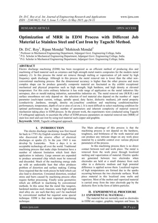
- 2. Dr. D.C. Roy et al. Int. Journal of Engineering Research and Applications www.ijera.com ISSN : 2248-9622, Vol. 5, Issue 5, ( Part -3) May 2015, pp.24-31 www.ijera.com 25 | P a g e this present work copper and graphite are taken as the tool material. Both electrode are prepared with dia. Φ-6m.m. and length of 45 mm. and stainless steel(SUS410) and cast iron (HT200)are taken as work material both have wide range of application in industrial filed like manufacturing ,cryogenic, space application etc. the spectra analysis results for the composition of the work piece are listed as under Table 1. Chemical composition of stainless steel Element C Si Mn P S Cr Pb Comp(%wt) 0.12 0.95 0.97 0.039 0.029 12.58 0.047 Table 2. Chemical composition of cast iron Element C Si Mn P S Cr Comp(%wt) 3.27 1.96 0.67 0.17 0.14 4.20 Table 3. Major properties of the tool and work piece are listed as flows: Material Property Tool Material Work Piece Copper Graphite Stainless steel Cast iron Density 8940 kg/m3 2157 kg/m3 7850 kg/m3 7570 kg/m3 Thermal conductivity 401 Wm-1 k-1 130 Wm-1 k-1 18 Wm-1 k-1 55 Wm-1 k-1 Electrical resistivity 16.78 nΩm(at 200 C) 10 nΩm(at 200 C) 69 nΩm(at 200 C 10 nΩm(at 200 C Specific heat capacity 0.385J/g 0 C 0.72 J/g 0 C 0.49 J/g 0 C 0.46 J/g 0 C Melting point 1085 0 C 43000 C 1535 0 C 1200 0 C 2.2DESIGN OF EXPERIMENT In this present work we have experimental research work at MSME tool room, Kolkata with different work pieces, stainless steel (112*47*11) and cast iron (d=50mm, h=12 mm) and different tool materialscopperand graphite(dia. φ=6mm, h=70 mm). The whole experiments have been done by electro discharge machine, modelAGITRON COMPACT -1 (die sinking type) and the positive polarity for electrode is used to conduct the experiments. RUSTLICK E.D.M. 20 oil is used as dielectric fluid which specific gravity 0.763 and freezing point 930 C Fig.-1 Working principle of EDM machine 2.3 PARAMETERS AND RANGE SELECTION In this present work I have selected the parameter as below.
- 3. Dr. D.C. Roy et al. Int. Journal of Engineering Research and Applications www.ijera.com ISSN : 2248-9622, Vol. 5, Issue 5, ( Part -3) May 2015, pp.24-31 www.ijera.com 26 | P a g e Table-4 Parameter selection Parameters Symbol Level Low Medium High Electrode speed (mm/min) S 500 600 700 Current(amp) I 3 4 5 Depth of cut(mm) h 2 3 4 III. TAGUCHI L9 ORTHOGONAL ARRAY Table-5 orthogonal array Exp. No Control factor A B C 1 1 1 1 2 1 2 2 3 1 3 3 4 2 1 2 5 2 2 3 6 2 3 1 7 3 1 2 8 3 2 3 9 3 3 1 IV. OBSERVATION TABLE EXPERIMENT NO. 1 Table -6. Work piece-CAST IRON Electrode-COPPER Dia. φ=6mm Exp. no Spark gap(mm) Electrode speed(mm/min) Current (amp) Depth of cut(mm) Machining time(sec) MRR (mm3 /min) 1 0.14 500 3 2 432 8.6075 2 0.20 500 4 3 611 9.4810 3 0.23 500 5 4 685 11.488 4 0.14 600 3 3 688 8.107 5 0.20 600 4 4 832 9.283 6 0.23 600 5 2 260 15.133 7 0.14 700 3 4 1042 7.137 8 0.20 700 4 2 310 12.45 9 0.23 700 5 3 461 12.80 EXPERIMENT NO. 2 Table -7 Work piece-CAST IRON Electrode-GRAPHITE Dia. φ=6mm Exp. no Spark gap(mm) Electrode speed(mm/min) Current (amp) Depth of cut(mm) Machining time(sec) MRR (mm3 /min) 1 0.14 500 3 2 468 7.945 2 0.20 500 4 3 681 8.506 3 0.23 500 5 4 823 9.553 4 0.14 600 3 3 744 7.490 5 0.20 600 4 4 895 8.622 6 0.23 600 5 2 316 12.440 7 0.14 700 3 4 1026 7.248 8 0.20 700 4 2 448 8.620 9 0.23 700 5 3 504 11.710
- 4. Dr. D.C. Roy et al. Int. Journal of Engineering Research and Applications www.ijera.com ISSN : 2248-9622, Vol. 5, Issue 5, ( Part -3) May 2015, pp.24-31 www.ijera.com 27 | P a g e EXPERIMENT NO. 3 Table -8 Work piece-STAINLESS STEEL Electrode-COPPER Dia. φ=6mm Exp. no Spark gap(mm) Electrode speed(mm/min) Current (amp) Depth of cut(mm) Machining time(sec) MRR (mm3 /min) 1 0.14 500 3 2 694 5.35 2 0.20 500 4 3 1129 5.13 3 0.23 500 5 4 1320 5.96 4 0.14 600 3 3 695 8.03 5 0.20 600 4 4 956 8.07 6 0.23 600 5 2 330 11.92 7 0.14 700 3 4 643 11.56 8 0.20 700 4 2 218 17.715 9 0.23 700 5 3 297 19.87 EXPERIMENT NO. 4 Table-9 Work piece-CAST IRON Electrode-GRAPHITE Dia. φ=6mm Exp. no Spark gap(mm) Electrode speed(mm/min) Current (amp) Depth of cut(mm) Machining time(sec) MRR (mm3 /min) 1 0.14 500 3 2 1735 2.143 2 0.20 500 4 3 4409 1.308 3 0.23 500 5 4 8525 1.919 4 0.14 600 3 3 2742 4.293 5 0.20 600 4 4 5254 3.092 6 0.23 600 5 2 964 0.86 7 0.14 700 3 4 3538 4.459 8 0.20 700 4 2 643 1.428 9 0.23 700 5 3 1651 7.6086 V. CALCULATION OF MATERIAL REMOVAL RATE ( MRR) Material removal rate refers to the amount of metal removed from work piece per unit time. MRR = 𝑉𝑂𝐿𝑈𝑀𝐸 𝑇𝐼𝑀𝐸 = 𝜋 4 ℎ 𝑡𝑖𝑚𝑒 d2 mm3 /min [Where d = diameter of electrode, h = depth of cut] VI. REGRESSION ANALYSIS In statistics, regression analysis is a statistical process for estimating therelationships among variables. It includes many techniques for modeling and analyzing several variables, when the focus is on the relationship between dependent and one or more independentvariables. More specifically, regression analysis helps one understand how the typical value of the dependent variable changes when any one of the independent variables is varied, while the other independent variables are held fixed (wiki). In this problem there is more than one predictor variable is involve so simple regression can’t be used (4). So need to help multiple regression analysis. Multiple regression analysis have two type i) simple multiple regression analysis (first order regression analysis) ii) polynomial multiple regression analysis (second order regression analysis) Simple multiple regression analysis is represented by the equation of first order regression Y= β0+β1X1+β2X2+β3X3+…………………..+ε Where β is constant terms & X is the variables & ε is the experimental error. Polynomial multiple regression analysis equation is Y = β 0 + β1X1+β2X2 +β3X3 + β 4 X1 2 + β 5 X2 2 + β6X3 2 + β7 X1X2 + β8 X2 X3 + β9 X1 X3 The above equation is second order polynomial equation for 3 variables. Where β are constant, X1, X2, X3 are the linear terms. Here, MRR is Response variable, Electrode Speed (S), Current (I), Depth of Cut (h) are the predictor variables. Polynomial regression equation becomes after replacing real problem variables MRR = β0 + β1(S) + β2(I) + β3(h) + β 4 (S)*(S) + β 5 (I)*(I) + β6 (h)*(h) + β7 (S)*(I) + β8 (I)*(h) + β9 (S)*(h) ………….. (1) To solve this equation following matrix method is used MRR= [β] [X] ……………….. (2) [β]= [MRR] [X-1 ]
- 5. Dr. D.C. Roy et al. Int. Journal of Engineering Research and Applications www.ijera.com ISSN : 2248-9622, Vol. 5, Issue 5, ( Part -3) May 2015, pp.24-31 www.ijera.com 28 | P a g e where [β] is the coefficient matrix, MRR is the response variable matrix; [X-1 ] is the inverse of predictor variable matrix ……………….(3) In this problem there are 3 independent variables and each variable has 3 levels and hence from the Taguchi Orthogonal Array (OA) table L9 OA is best selected VII. RESULTS AND DICUSSIONS Value of coefficients for the predicted equation β0 = 6.8541, β1 =0.0585, β2 =-3.1504, β3 =-16.4153, β4 =0.0001, β5 =1.3254, β6 =-0.8858, β7 =-0.0278, β8 =4.3390, β9 =0.0047 So, the Predicted equation is VIII. Percentage Difference between Experimental & Predicted MRR Table-10 Work piece-CAST IRON Electrode-COPPER Dia. φ=6mm SL. no Electrode speed(mm/min) Current (amp) Depth of cut(mm) Experimental MRR (mm3 /min) Predicted MRR (mm3 /min) 1 500 3 2 8.6075 7.041867 2 500 4 3 9.481 7.872567 3 500 5 4 11.488 9.836667 4 600 3 3 8.107 8.035867 5 600 4 4 9.283 9.160567 6 600 5 2 15.133 15.04627 7 700 3 4 7.137 8.831067 8 700 4 2 12.45 14.18577 9 700 5 3 12.8 14.47587 Table-11 Work piece-CAST IRON Electrode-GRAPHITE Dia. φ=6mm SL. no Electrode speed(mm/min) Current (amp) Depth of cut(mm) Experimental MRR (mm3 /min) Predicted MRR (mm3 /min) 1 500 3 2 7.945 4.556689 2 500 4 3 8.506 4.991289 3 500 5 4 9.553 12.54589 4 600 3 3 7.49 6.178089 5 600 4 4 8.622 5.896689 6 600 5 2 12.44 11.78029 7 700 3 4 7.248 9.092689 8 700 4 2 8.62 12.54229 9 700 5 3 11.71 14.55009 Table-12 Work piece-STAINLESS STEEL Electrode-COPPER Dia. φ=6mm SL. no Electrode speed(mm/min) Current (amp) Depth of cut(mm) Experimental MRR (mm3 /min) Predicted MRR (mm3 /min) 1 500 3 2 5.35 2.5335 2 500 4 3 5.13 2.3006 3 500 5 4 5.96 11.6249 4 600 3 3 8.03 6.9762 5 600 4 4 8.07 7.0007 6 600 5 2 11.923 10.8851 7 700 3 4 11.56 12.5873 8 700 4 2 17.71 18.7789 9 700 5 3 19.87 20.9158 MRR=6.8541+0.0585(S)-3.1504(I) - 16.4153(h) +0.0001(S2 ) +1.3254(I2 )- 0.8858(h2 ) - 0.0278(S*I) + 4.3390(I*h) + 0.0047 (h*S)
- 6. Dr. D.C. Roy et al. Int. Journal of Engineering Research and Applications www.ijera.com ISSN : 2248-9622, Vol. 5, Issue 5, ( Part -3) May 2015, pp.24-31 www.ijera.com 29 | P a g e Table-13 Work piece-CAST IRON Electrode-GRAPHITE Dia. φ=6mm SL. no Electrode speed(mm/min) Current (amp) Depth of cut(mm) Experimental MRR (mm3 /min) Predicted MRR (mm3 /min) 1 500 3 2 2.14 2.277922 2 500 4 3 1.3 3.177222 3 500 5 4 1.91 13.68348 4 600 3 3 4.29 2.383278 5 600 4 4 3.09 1.113978 6 600 5 2 0.86 1.148922 7 700 3 4 4.459 5.524478 8 700 4 2 1.428 2.441578 9 700 5 3 7.608 8.542278 IX. Graphical Representation Fig. 2. MRR vs Electrode Speed Fig. 3.MRR vs Current 9.1547 10.7522 12.4747 14.3222 16.2947 18.3922 20.6147 22.9622 25.4347 0 5 10 15 20 25 30 MRR Electrod Speed (S) Graph of MRR vs Electrode Speed 1 1.5 2 2.5 3 3.5 4 4.5 5 0 1 2 3 4 5 6 0 1 2 3 4 5 6 7 8 9 10 MRR CURRENT (I) Graph of MRR vs Current
- 7. Dr. D.C. Roy et al. Int. Journal of Engineering Research and Applications www.ijera.com ISSN : 2248-9622, Vol. 5, Issue 5, ( Part -3) May 2015, pp.24-31 www.ijera.com 30 | P a g e Fig. 4.MRR vs Depth of Cut (h) X. CONCLUSION In this work we have shown, how the MRR is differed with the Electrode speed,Current and Depth of cut in different job material cast iron, stainless steel with the different tool material copper and graphite and we show in fig. (2) MRR depend on the electrode speed in hyperbolic relationship if the electrode speed increases MRR also increases as like hyperbolic carveand in fig (3) show that MRR linearly depends on applied current ,MRR increases proportionally with increase the applied current .Also show in fig(4) parabolic decrease with increase the depth of cut. and shown that, maximum MRR obtain for the combination of-Work piece-STAINLESS STEEL ,Electrode-COPPER ,spindle speed 700 rpm ,current 5amp, and depth of cut 4 mm. REFFERENCES Journal papers [1] Modeling and Analysis of Effects of Machining Parameters on MRR in EDM Process of Copper Tungsten Metal Matrix Composite(MMC) Mr. N. S. Payaghan*1, Mr. S. B. Ubale *2, Dr. M. S. Kadam *3 *1 PG Student, MGM‟s JNEC, Aurangabad, India *2 Asso.Prof. in Mechanical Engg. Dept., MGM‟s JNEC, Aurangabad, India *3 Professor and Head in Mechanical Engg. Dept., MGM‟s JNEC, Aurangabad, India [2] Parametric Analysis on the Effect of Cryogenic Treatment on the Work Piece Material of EDM Process N. Raghu Ram*, K. Venkata Rao, Ch. Lakshmi Kanth, M. Naga Swapna Sri Department of Mechanical Engineering, Prasad V.Potluri Siddhartha Institute of Technology, Kanuru, Vijayawada [3] Experimental Analysis of Electro-Discharge Machining Parameters for Minimum Tool Wear Rate on Machinability of Carbon Fiber/Epoxy Composites Using Taguchi Method Mohit Tiwari1, Kuwar Mausam2, Kamal Sharma3, Ravindra Pratap Singh4 1PG Student, 2Assistant Professor, 3Associate Professor, 4Assistant Professor Department of Mechanical Engineering, GLA University, Mathura (INDIA) [4] Study Of Investigations On Process Parameters Of Electro Discharge Sawing Using Taguchi Approach Kalley Harinarayana Research Scholar, Jawaharlal Nehru Technological University, Hyderabad Dr. B. Balu Naik Professor, Jawaharlal Nehru Technological University, Hyderabad Dr. N. N. Ramesh Professor, Jawaharlal Nehru Technological University, Hyderabad [5] Selection of machining parameter in EDM process with impulse flushing system using three different electrode materials Shailesh Dewangan1 Dr.C.K.Biswas2 and S N Sahu3 1 Ph D Research scholar Department of Mechanical Engineering National Institute of Technology, Rourkela Rourkela (Orissa) Email id- shaileshdewangan123@gmail.com 2 Associate Professor 3M-tech scholar Department of Mechanical Engineering National Institute of Technology, Rourkela Rourkela(Orissa) [6] R. Snoeys, F. Staelens, and W. Dekeyser. Current trends in nonconventional material removal processes. CIRP Annals – Manufacturing Technology, 35(2):467–480, 1986. 16.963 16.9620125 16.8503 16.6278625 16.2947 15.8508125 15.2962 14.6308625 13.8548 10 11 12 13 14 15 16 17 18 19 20 0 1 2 3 4 5 6 7 8 9 10 MRR Depth of Cut (h) Graph of MRR vs Depth of Cut (h)
- 8. Dr. D.C. Roy et al. Int. Journal of Engineering Research and Applications www.ijera.com ISSN : 2248-9622, Vol. 5, Issue 5, ( Part -3) May 2015, pp.24-31 www.ijera.com 31 | P a g e [7] Ross P J. Taguchi techniques for quality engineering. McGraw-Hill,New york, 1988. [8] Droza T J. Tool and Manufacturing Engineering; Handbook; Machining. USA: Society of Manufacturing Engineering, 1998. [9] F.L. Amorima and W.L. Weingaertner. The behavior of graphite and copper electrodes on the finish die-sinking electrical discharge machining (EDM) of AISI P20 tool steel. Journal of the Braz. Soc. of Mech. Sci. & Eng., 29:4 / 367, 2007. [10] H S Payal, C. Rajesh, and Singh Sarabjeet. Analysis of electro discharge machined surface of EN-31 tool steel. International Journal of Machine Tools and Manufacture, 67:1465–1471, Nov 2008.