Download to read offline

![International Journal of Mechanical Engineering and Technology (IJMET), ISSN 0976 – 6340(Print),
ISSN 0976 – 6359(Online), Volume 5, Issue 6, June (2014), pp. 101-109 © IAEME
ceramic (ultra-hard conductive material) since the hardness of the workpiece has no effect on the
process. Unlike the traditional cutting and grinding processes, which depends on the force generated
by a harder tool to remove the softer material workpiece, the EDM process is free from contact force
and chatter vibration. Furthermore, EDM permits the machining to be done even after the hardening
process. The EDM process has been used in high precision machining of metals, and to date, there
are several different types of EDM systems that have been developed for a particular industrial
application. EDM is widely used for making mold and dies and finishing parts for automotive
industry, aerospace and surgical components [1]. Two principle types of EDM processes are the die
sinking and the wire cut EDM process. Die sinking type EDM machine requires an electrode to
machine the workpiece. Wire cut EDM machine uses a continuous wire as the electrode to cut the
workpiece. Rajurkar [2] explained some future trends study in EDM such as machining advanced
materials, mirror surface finish using powder additives, ultrasonic-assisted EDM, control and
automation.
102
One of the field interests is to study the optimal selection of process parameters which will
increase production rate considerably by reducing the machining time. An optimum selection of
machining parameters for the best process performance is still uncertain since EDM process is a
complex and stochastic process.
The objective of the present work is to investigate MRR of SS 316 and EWR of copper by
using die sinking EDM and to optimize these performance characteristics for obtaining maximum
MRR and minimum EWR.
2. EXPERIMENTAL DETAILS
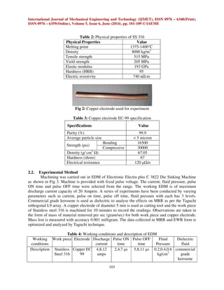
2.1. Experimental Materials
Stainless steel 316 is chosen as the work piece material and copper EC-99 as the tool
electrode material.
Table 1: Chemical composition of stainless steel 316.
Fe C Cr Ni Mo Mn Si P S
remaining 0.03% 16-18.5% 10-14% 2-3% 2% 1% 0.045% 0.03%
Fig 1: SS 316 used for experiment](https://image.slidesharecdn.com/30120140506011-2-140924013758-phpapp01/85/30120140506011-2-2-320.jpg)
![International Journal of Mechanical Engineering and Technology (IJMET), ISSN 0976 – 6340(Print),
ISSN 0976 – 6359(Online), Volume 5, Issue 6, June (2014), pp. 101-109 © IAEME
109
REFERENCES
[1] K.H. Ho, S.T. Newman, State of the art electrical discharge machining (EDM), International
Journal of Machine Tools Manufacture 43 (2003) 1287-1300.
[2] K.P. Rajurkar, Nontraditional manufacturing processes, in: R.C. Dorf, A. Kusiak (Eds.),
Handbook of Design, Manufacturing and Automation, John Wiley Sons Inc., USA, 1994.
[3] S. Kuriakose, M.S. Shunmugam, Multi objective optimization of wire-electro discharge
machining process by genetic algorithm, J. Mater. Process Technol. 170 (2005) 133-141.
[4] K. Wang, H.L. Gelgele, Y. Wang, Q. Yuan, M. Fang, A hybrid intelligent method for
modelling the EDM process, Int. J. Machine Tools Manuf. 43 (2003) 995-999.
[5] C.L. Lin, J.L. Lin, T.C. Ko, Optimization of the EDM process based on the orthogonal
array with fuzzy logic and grey relational analysis method, International J. Adv. Manuf.
Technol. 19 (2002) 271-277.
[6] J.L. Lin, C.L. Lin, The use of grey-fuzzy logic for the optimization of the manufacturing
process, J. Mater. Process. Technol. 160 (2005) 9-14.
[7] J.C. Su, J.Y. Kao, Y.S. Tarng, Optimization of the electrical discharge machining process
using a GA-based neural network, Int. J. Advance Manufacturing Technology 24 (2004)
81-90.
[8] C. Fenggou, Y. Dayong, The study of high efficiency and intelligent optimization system in
EDM sinking process, J. Mater. Process. Technol. 149 (2004) 83-87.
[9] A. Yahya, C.D. Manning, Determination of material removal rate of an electro-discharge
machine using dimensional analysis, Journal of Physics D: Applied Physics 37 (2004)
1467-1471.
[10] A. Yahya, Digital control of an electro discharge Machining (EDM) system, Ph.D. Thesis,
Loughborough University, 2005.
[11] Lin, J.L., Lin, C.L., The use of the orthogonal array with grey relational analysis to optimize
the electrical discharge machining process with multiple performance characteristics,
International Journal of Machine Tools Manufacture, Vol. 44, pp.237-244 2002.
[12] S. Dhanabalan, K. Sivakumar Optimization of EDM Process Parameters with Multiple
Performance Characteristics for Titanium Grades European Journal of Scientific Research.
[13] A. Parshuramulu, K. Buschaiah, P. Laxminarayana, “A Study on Influence of Polarity on
the Machining Characteristics o Sinker EDM”, International Journal of Advanced Research
in Engineering Technology (IJARET), Volume 4, Issue 3, 2013, pp. 158 - 162, ISSN Print:
0976-6480, ISSN Online: 0976-6499.
[14] K.L.Uday Kiran, R.Rajendra, G.Chandramohan Reddy, A.M.K Prasad, “Comparative
Study on Variation of Process Characteristics on Al and Die Steel Components in Sink EDM
Process”, International Journal of Advanced Research in Engineering Technology
(IJARET), Volume 4, Issue 3, 2013, pp. 170 - 177, ISSN Print: 0976-6480, ISSN Online:
0976-6499.
[15] S. K. Sahu, Saipad Sahu, “A Comparative Study on Material Removal Rate by
Experimental Method and Finite Element Modelling in Electrical Discharge Machining”,
International Journal of Mechanical Engineering Technology (IJMET), Volume 4, Issue 5,
2013, pp. 173 - 181, ISSN Print: 0976 – 6340, ISSN Online: 0976 – 6359.](https://image.slidesharecdn.com/30120140506011-2-140924013758-phpapp01/85/30120140506011-2-9-320.jpg)

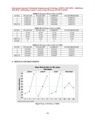
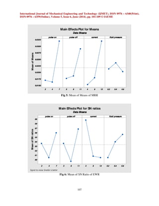
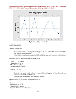
This document summarizes a study on optimizing electric discharge machining (EDM) parameters to maximize material removal rate (MRR) and minimize electrode wear rate (EWR) when machining stainless steel 316 with a copper electrode. Experiments were conducted using a Taguchi design of experiments with four machining parameters (pulse on time, pulse off time, current, fluid pressure) each at three levels. Results showed that pulse off time and current had the most significant effects on MRR and EWR, respectively. Specifically, MRR increased with longer pulse off times while EWR decreased at higher currents. The optimal settings found were a current of 12 amps and long pulse off time to achieve maximum MRR during EDM of