Maximizing EDM MRR Using Taguchi Analysis
•
0 likes•333 views

This document describes a study that uses Taguchi analysis to determine the optimal machining parameters for maximizing material removal rate (MRR) in electro discharge machining (EDM) processes. Experiments were conducted using copper and graphite electrodes on mild steel and aluminum workpieces. The parameters varied were electrode speed, current, and depth of cut. Regression analysis was used to develop a polynomial equation relating MRR to the machining parameters. The experiments followed a Taguchi L9 orthogonal array design with three levels of each parameter. Observations of machining time and calculated MRR were recorded for each experimental run.

Recommended
Recommended
More Related Content
What's hot
What's hot (20)
Viewers also liked
Viewers also liked (20)
Similar to Maximizing EDM MRR Using Taguchi Analysis
Similar to Maximizing EDM MRR Using Taguchi Analysis (20)
Recently uploaded
Recently uploaded (20)
Maximizing EDM MRR Using Taguchi Analysis
- 1. Dr. D.C. Roy Int. Journal of Engineering Research and Applications www.ijera.com ISSN : 2248-9622, Vol. 5, Issue 3, ( Part -3) March 2015, pp.59-66 www.ijera.com 59 | P a g e A Comparative Study to Maximize MRR in Electro Discharge Machining Process by Variation of Control Parameters Using Taguchi Analysis Dr. D.C. Roy 1 , Akhtarujjaman Sarkar 2 1 Professor, Department of Mechanical Engineering, Jalpaiguri Government Engineering College, India 2 Post Graduate Scholar, Department of Mechanical Engineering, Jalpaiguri Government Engineering College, India. ABSTRACT Electro Discharge Machining (EDM) is a non-traditional machining process, based on thermo electric energy between the work piece and electrode. In this process, the material removal is occurred electro thermally by a series of successive discrete discharges between electrode and the work piece. Electro Discharge Machine which has the ability to machine hard, difficult to machine material and parts with internal complex shape by using precisely controlled sparks that occurs between electrode and work piece in the presence of dielectric fluid. This spark removes material from both work piece and electrode. Material Removal Rate (MRR) is of crucial importance in this process. In this research experiment has been done along with Copper and Graphite tool material as well as Mild Steel and Aluminium material has been used as work piece. Three major Parameters named as Electrode Speed (V), Current (I), and Depth of Cut (h) are considered to determine the MRR. In this experiment three levels of each parameter has been taken by using Taguchi L9 orthogonal array to find out the best combination of electrode and work piece at the optimal setting of control parameters for maximum Material Removal Rate. .Keywords: Current, Depth of Cut, Electrode Speed, MRR, Taguchi Analysis. I. INTRODUCTION There has been rapid growth in the development of harder and difficult to machine metals and alloys during last two decades. Machining process that involves chip formation have number of inherent limitations which limit their application in industry. Large amount of energy are expended to produce unwanted chips which must be removed and discarded. Electro Discharge Machining Process is now become the most important accepted technologies in manufacturing industries since may many complex 3D shapes can be machined using simple shaped tool electrode. EDM is an important non-traditional manufacturing method. The basis of Electro Discharge Machining (EDM) was first traced far back in 1770’s by English scientist Joseph Priesty who discovered the erosive effect of electrical discharges of sparks. The EDM technique was developed by two Russian scientists B.R Lazarenko and N.I Lazarenko in the year 1943. Electrical- discharge machining (EDM) is an unconventional, non-contact machining process where metal removal is based on thermo-electric principles. In this process, the material removal mechanism uses the electrical energy and turns it into thermal energy through a series of discrete electrical discharges occurring between the electrode and work piece immersed in an insulating dielectric fluid . Its unique feature of using thermal energy is to machine electrically conductive parts regardless of their hardness; its distinctive advantage is in the manufacture of mould, die, automotive, aerospace and other applications. Moreover, EDM does not make direct contact between the electrode and the work piece, eliminating mechanical stresses, chatter and vibration problems during machining. Hence, the tool material is generally softer than the work piece material. A dielectric fluid is required to maintain the sparking gap between the electrode and work piece. This dielectric fluid is normally a fluid. Dielectric fluid is used in EDM machine provides important functions in this process. These are : (i) Controlling the sparking gap spacing (ii) Cooling the heated material to form the chip and (iii) Removing chips from the sparking area. EDM process is basically of two types : (i) Die sinking EDM ( ii). Wire cut EDM. We have been performed this experiment by using Die-Sinking type Electro Discharge Machine. Material Removal Rate (MRR) is an important performance measure in EDM process. MRR is mainly dependent on the different input machining parameters, electrode and work piece. It is found already many works has been done on optimization of MRR but very little work has been done on RESEARCH ARTICLE OPEN ACCESS
- 2. Dr. D.C. Roy Int. Journal of Engineering Research and Applications www.ijera.com ISSN : 2248-9622, Vol. 5, Issue 3, ( Part -3) March 2015, pp.59-66 www.ijera.com 60 | P a g e optimization of MRR for different material and different electrode in EDM. In this work study on EDM relating to analyze the variation of Material Removal Rate with control parameters and predict the Maximum Material Rate (MRR) at optimal setting of control parameters by using Taguchi L9 orthogonal Array. Electrode Speed (V), Current (I) and Depth of Cut (h) are the basic variable and three levels of each parameter are taken in this experimental study. II. EXPERIMENTAL SET-UP We have done this experimental research work at MSME tool room, Kolkata with different Work piece and different electrode. The whole experiments have been done by Electro Discharge Machine, model AGITRON COMPACT-1 (Die- Sinking type) and positive polarity for electrode is used to conduct the experiments. The materials that are normally used as electrodes in this EDM are copper, graphite, tungsten and brass. Copper and Graphite are selected as tool/electrode in this experiment. Electrodes are prepared with the diameter of 8 mm. Mild Steel and Aluminium are selected as work piece. One piece Mild Steel and one piece Aluminium is prepared with dimension of (101*62*9.7) mm3 and (110*65.3*15) mm3 respectively for this experimental work . These two electrodes copper and graphite is expected to give better MRR and it is major commercially available EDM electrodes. The work piece material are used for this work are mild Steel and Aluminum which is having a wide applications in industrial field like manufacturing, cryogenic, space application etc. RUSTLICK E.D.M. 20 oil ( specific gravity = 0.763, freezing point = 940 C ) is used as Dielectric Fluid in this experiment. Component of EDM III. PARAMETERS AND RANGE SELECTION In this study L9 orthogonal array has been used which is attributed to its suitability for three level problems. On the basis of Taguchi method three factors with three levels of each are selected and L9 array has been made for calculating MRR. We have been selected the following suitable level values of various factors. Parameters Symbol Level Low Medium High Electrode Speed (mm/min) V 500 600 700 Current (Amp) I 4 6 8.5 Depth of Cut (mm) h 2 3 4
- 3. Dr. D.C. Roy Int. Journal of Engineering Research and Applications www.ijera.com ISSN : 2248-9622, Vol. 5, Issue 3, ( Part -3) March 2015, pp.59-66 www.ijera.com 61 | P a g e Taguchi L9 Orthogonal Array Control Factors Exp. No A B C 1 1 1 1 2 1 2 2 3 1 3 3 4 2 1 2 5 2 2 3 6 2 3 1 7 3 1 3 8 3 2 1 9 3 3 2 IV. OBSERVATION TABLE Work Piece- Aluminium Electrode- Copper Table - 1 Exp. No Impulse Spark Gap (mm) Electrode Speed (mm/min) Current (Amp) Depth of Cut (mm) Machining Time (min) MRR (mm3 /min) 1 1060 0.20 500 4 2 7.167 14.730 2 1070 0.26 500 6 3 5.033 31.924 3 1080 0.31 500 8.5 4 4.50 48.186 4 1060 0.20 600 4 3 8.167 19.390 5 1070 0.26 600 6 4 6.10 35.120 6 1080 0.31 600 8.5 2 1.75 61.953 7 1060 0.20 700 4 4 10.233 20.633 8 1070 0.26 700 6 2 2.133 50.219 9 1080 0.31 700 8.5 3 2.367 68.706 Work Piece - Aluminium Electrode- Graphite Table - 2 Exp. No Impulse Spark Gap (mm) Electrode Speed (mm/min) Current (Amp) Depth of Cut (mm) Machining Time (min) MRR (mm3 /min) 1 1060 0.20 500 4 2 7.50 14.076 2 1070 0.26 500 6 3 6.317 25.435 3 1080 0.31 500 8.5 4 4.467 38.950 4 1060 0.20 600 4 3 9.0 17.500 5 1070 0.26 600 6 4 7.317 29.279 6 1080 0.31 600 8.5 2 2.233 48.553 7 1060 0.20 700 4 4 10.333 20.433 8 1070 0.26 700 6 2 2.567 41.728 9 1080 0.31 700 8.5 3 2.75 59.137 Work Piece - Mild Steel Electrode - Copper Table - 3 Exp. No Impulse Spark Gap (mm) Electrode Speed (mm/min) Current (Amp) Depth of Cut (mm) Machining Time (min) MRR (mm3 /min) 1 1060 0.20 500 4 2 13.75 7.678 2 1070 0.26 500 6 3 13.167 12.203 3 1080 0.31 500 8.5 4 9.5 22.825 4 1060 0.20 600 4 3 18.75 8.445 5 1070 0.26 600 6 4 15.533 13.792 6 1080 0.31 600 8.5 2 3.95 27.447 7 1060 0.20 700 4 4 23.667 9.315 8 1070 0.26 700 6 2 6.0 17.853 9 1080 0.31 700 8.5 3 4.417 36.818
- 4. Dr. D.C. Roy Int. Journal of Engineering Research and Applications www.ijera.com ISSN : 2248-9622, Vol. 5, Issue 3, ( Part -3) March 2015, pp.59-66 www.ijera.com 62 | P a g e Work Piece - Mild Steel Electrode - Graphite Table - 4 Exp. No Impulse Spark Gap (mm) Electrode Speed (mm/min) Current (Amp) Depth of Cut (mm) Machining Time (min) MRR (mm3 /min) 1 1060 0.20 500 4 2 26.667 3.959 2 1070 0.26 500 6 3 31.20 5.150 3 1080 0.31 500 8.5 4 30.0 7.228 4 1060 0.20 600 4 3 38.333 4.130 5 1070 0.26 600 6 4 38.933 5.503 6 1080 0.31 600 8.5 2 14.0 7.749 7 1060 0.20 700 4 4 48.333 4.368 8 1070 0.26 700 6 2 17.367 6.168 9 1080 0.31 700 8.5 3 19.0 8.560 V. CALCULATION OF MRR Material Removal Rate (MRR) refers to the amount of material removed from work piece per unit time. Material removal rate is calculated by measuring the cross section area of cut multiplying with the depth of cut then it is divided by machining time. Material Removal Rate (MRR) = 𝑉𝑜𝑙𝑢𝑚𝑒 𝑇𝑖𝑚𝑒 = 𝜋 4∗𝐷2∗ℎ 𝑇𝑖𝑚𝑒 mm3 /min [ Where D = Diameter of Electrode, h = Depth of Cut ] VI. REGRESSION ANALYSIS Regression analysis is the relationship between various variables. By regression analysis one can construct a relationship between response variable and predictor variable. It demonstrates what will be the changes in response variable because of the changes in predictor variable. Simple regression equation is y=a+ b x In this problem more than one predictor variable is involved and hence simple regression analysis cannot be used. We have to take the help of multiple regression analysis. There are two types of multiple regression analysis- (i) Simple multiple regression analysis (regression equation of first order) (ii) Polynomial multiple regression analysis (regression equation of second order or more) Simple multiple regression analysis is represented by the equation of first order regression Y= β0+β1X1+β2X2+β3X3+…………………..+ε Where β is constant terms & X is the variables & ε is the experimental error. Polynomial multiple regression analysis equation is Y = β0+ β1X1+β2X2+β3X3+ β 11X2 11+ β 22X2 22+ β33X2 33+ β12X1X2+ β13X2X3+ β23X1X3 The above equation is second order polynomial equation for 3 variables. Where β are constant, X1 , X2 , X3 are the linear terms, X12 X13 X23 are the interaction terms between the factors, and lastly X11 X22 X33 are the square terms. Here, MRR is Response variable, Electrode Speed (V), Current (I), Depth of Cut (h) are the predictor variables. Polynomial regression equation becomes after replacing real problem variables MRR = β0 + β1(V) + β2(I) + β3(h) + β11(V)*(V) + β 22(I)*(I) + β33(h)*(h) + β12(V)*(I) + β23(I)*(h) + β13(V)*(h) …………..(1) To solve this equation following matrix method is used MRR= [β][ X ]………………..(2) [β]=[MRR] [X-1 ] where [β] is the coefficient matrix, MRR is the response variable matrix; [X-1 ] is the inverse of predictor variable matrix……………….(3) In this problem there are 3 independent variables and each variable has 3 levels and hence from the Taguchi Orthogonal Array (OA) table L9 OA is best selected.
- 5. Dr. D.C. Roy Int. Journal of Engineering Research and Applications www.ijera.com ISSN : 2248-9622, Vol. 5, Issue 3, ( Part -3) March 2015, pp.59-66 www.ijera.com 63 | P a g e Experiments have been carried out using Taguchi’s L9 Orthogonal array experimental design which consist of 9 combination of Electrode Speed, Current, and Depth of Cut. It considers three process parameters to be varied three discrete levels. The experimental design has been shown in above table. Replacing the value of three variables in the polynomial regression equation….(1) we get the following equations according to the Taguchi L9 table. MRR= β0+500 β1+4 β2+2 β3+250000 β4+16 β5+4 β6+2000 β7+8 β8+1000β9 MRR = β0+500 β1+6 β2+3 β3+250000 β4+36 β5+9 β6+3000 β7+18 β8+1500 β9 MRR = β0+500 β1+8.5 β2+4 β3+250000 β4+72.25 β5+16 β6+4250 β7+34β8+2000 β9 MRR = β0+600 β1+4 β2+3 β3+360000 β4+16 β5+9 β6+2400 β7+12 β8+1800 β9 MRR = β0+600 β1+6 β2+4 β3+360000 β4+36β5+16 β6+3600 β7+24 β8+2400 β9 MRR= β0+600 β1+8. 5 β2+2 β3+ 360000β4+72.25 β5+4 β6+5100 β7+17 β8+1200 β9 MRR= β0+700 β1+4β2+4 β3+490000β4+16 β5+16 β6+2800 β7+16 β8+2800 β9 MRR= β0+700 β1+6 β2+2 β3+ 490000β4+36 β5+4 β6+4200β7+12 β8+1400 β9 MRR = β0+700 β1+8. 5 β2+3 β3+490000 β4+72.25 β5+9 β6+5950 β7+25.5 β8+2100 β9 VII. RESULTS AND DISCUSSIONS Value of Coefficients for the Predicted Equation β0 = -2.514, β1 = -0.1562, β2 = 0.1808, β3 = 28.4601, β4 = 0.0002, β5 = 0.0172, β6 = 0.9305, β7 = 0.0197, β8 = - 1.3485, β9 = -0.0457 Predicted Equation from Regression Analysis for Maximum MRR MRR = -2.514 - 0.1562(V) + 0.1808(I) + 28.4601(h) + 0.0002(V)*(V) + 0.0172(I)*(I) + 0.9305(h)*(h) + 0.0197(V)*(I) - 1.3485(I)*(h) - 0.0457(V)*(h) Results Showing the Experimental and Predicted Value of MRR Work Piece - Aluminium Electrode- Copper Table - 5 Exp. No Electrode Speed (mm/min) Current (Amp) Depth of Cut (mm) Experimental MRR (mm3 /min) Predicted MRR (mm3 /min) 1 500 4 2 14.730 13.939 2 500 6 3 31.924 31.122 3 500 8.5 4 48.186 47.370 4 600 4 3 19.390 19.357 5 600 6 4 35.120 35.074 6 600 8.5 2 61.953 61.893 7 700 4 4 20.633 21.497 8 700 6 2 50.219 51.070 9 700 8.5 3 68.706 69.539 Work Piece - Aluminium Electrode- Graphite Table - 6 Exp. No Electrode Speed (mm/min) Current (Amp) Depth of Cut (mm) Experimental MRR (mm3 /min) Predicted MRR (mm3 /min) 1 500 4 2 14.076 12.425 2 500 6 3 25.435 23.806 3 500 8.5 4 38.950 37.348 4 600 4 3 17.500 17.380 5 600 6 4 29.279 29.185 6 600 8.5 2 48.553 48.488 7 700 4 4 20.433 22.122 8 700 6 2 41.728 43.443 9 700 8.5 3 59.137 60.890
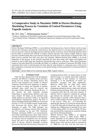
- 6. Dr. D.C. Roy Int. Journal of Engineering Research and Applications www.ijera.com ISSN : 2248-9622, Vol. 5, Issue 3, ( Part -3) March 2015, pp.59-66 www.ijera.com 64 | P a g e Work Piece - Mild Steel Electrode- Copper Table - 7 Exp. No Electrode Speed (mm/min) Current (Amp) Depth of Cut (mm) Experimental MRR (mm3 /min) Predicted MRR (mm3 /min) 1 500 4 2 7.678 9.694 2 500 6 3 12.203 14.179 3 500 8.5 4 22.825 24.757 4 600 4 3 8.445 8.578 5 600 6 4 13.792 13.882 6 600 8.5 2 27.447 27.562 7 700 4 4 9.315 7.221 8 700 6 2 17.853 15.799 9 700 8.5 3 36.818 34.702 Work Piece - Mild Steel Electrode- Graphite Table - 8 Exp. No Electrode Speed (mm/min) Current (Amp) Depth of Cut (mm) Experimental MRR (mm3 /min) Predicted MRR (mm3 /min) 1 500 4 2 3.959 3.123 2 500 6 3 5.150 4.317 3 500 8.5 4 7.228 6.398 4 600 4 3 4.130 4.084 5 600 6 4 5.503 5.460 6 600 8.5 2 7.749 7.697 7 700 4 4 4.368 5.255 8 700 6 2 6.168 7.044 9 700 8.5 3 8.560 9.440 Graphical Representation Figure: 1 Variation of MRR with Electrode Speed This figure:1 shows that the Material Removal Rate (MRR) increases with electrode speed increases. In the higher electrode speed the increment of MRR is more than the lower electrode speed.
- 7. Dr. D.C. Roy Int. Journal of Engineering Research and Applications www.ijera.com ISSN : 2248-9622, Vol. 5, Issue 3, ( Part -3) March 2015, pp.59-66 www.ijera.com 65 | P a g e Figure: 2 Variation of MRR with Current Figure:2 It shows that Material Removal Rate increases with Current increases linearly. Figure: 3 Variation of MRR with Depth of cut Figure:3 shows that Material Removal Rate (MRR) decreases with Depth of Cut increases. In lower depth of cut the decrement of MRR is more than higher depth of cut.
- 8. Dr. D.C. Roy Int. Journal of Engineering Research and Applications www.ijera.com ISSN : 2248-9622, Vol. 5, Issue 3, ( Part -3) March 2015, pp.59-66 www.ijera.com 66 | P a g e VIII. CONCLUSION (1) In this work we have used different work piece and electrode with different combination as like (i) Aluminium with Copper (ii) Aluminium with Graphite (iii) Mild steel with Copper and (iv) Mild Steel with Graphite by varying three parameter Electrode Speed, Current, and Depth of Cut to find out the best combination of Work piece and Electrode for maximum MRR. Finally it can be concluded that the best combination for maximum MRR is Work piece Aluminium and Electrode Copper. The optimal value of control parameters for maximum MRR are 700 mm/min Electrode Speed, 8.5 amp Current and 3 mm Depth of Cut. (2) In this experimental work we also concluded the variation of MRR with each control parameter are as follows: (a) From fig:1. It is concluded that the increase in Electrode Speed leads to increase in Material Removal Rate nonlinearly. (b) From fig:2. It is concluded that the increase in Current leads to increase in Material Removal Rate linearly. (c) And from fig:3. It is concluded that increase in Depth of Cut leads to decrease in the Material Removal Rate nonlinearly. REFERENCES Journal papers (1) Mohit Tiwari,Kuwar Mausam, Kamal Sharma, Ravindra Pratap Singh (2013) Experimental analysis of Electro Discharge Machining Parameters for minimum Tool Wear Rate on Machinability of carbon fiber/Epoxy composites using taguchi method. (2) N.Raghu Ram, K.Venkata Rao ,Ch. Lakshmi kanta, M. Naga Swapna Sri. (2014) Parametric Analysis on the effect of cryogenic treatment on the work piece material of EDM process. (3) Mohit Tiwari,Kuwar Mausam, Kamal Sharma, Ravindra Pratap Singh (2013) Investigate the optimal combination of process parameters for EDM by using Grey Relational Analysis (4) Vikash, Shashikant, A.K. Roy, Kaushik Kumar (2014) effect and Optimization Machine Process Parameters on MRR for EN19 & EN41 materials using Taguchi. (5) Mohammad reza Shabgard, Mirsadegh Seyedzavvar, Samad Nadimi Bavil Oliaei (2011) Influence of (6) Input Parameters on the characteristics of the EDM Process. Amandeep singh, Neel kanth grover, Rakesh Sharma (2012) Recent Advancement In Electric Discharge Machining, A Review Books (7) P.K Mishra, Non Conventional Machining