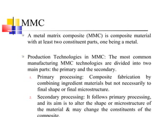
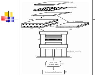
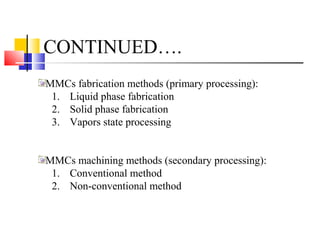
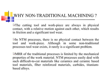
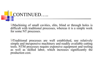
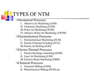
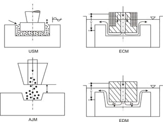
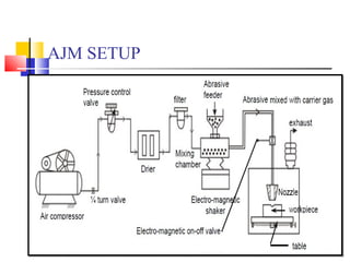
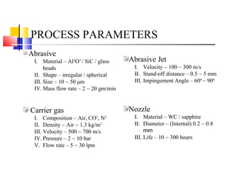
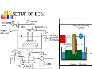
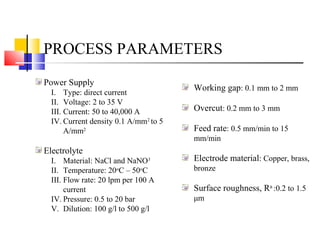
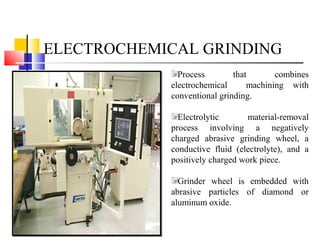
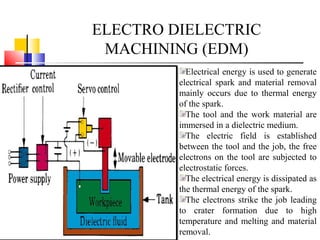
NON-TRADITIONAL
MACINING OF METAL
MATRIX COMPOSITES
Dr. Babasaheb Ambedkar Technological University Lonere-Raigarh
HARESH S. MAHALA
ROLL NO:MT2015408
HARESH S. MAHALA
ROLL NO:MT2015408
OUTLINE
Background of MMC
MMC
Processing of MMC
Why Non-Traditional Machining ?
Non Traditional Machining Processes
Future Scope
BACKGROUND OF MMC
Composites:
I. Composite materials are engineered or naturally
occurring materials made from two or more constituent
materials.
II. Most composites have two constituent materials: a
binder or matrix (polymers, metals, or ceramics) and
reinforcement (fibers, particles, flakes, and/or fillers).
III. Classification of composites:(i) Natural, and
(ii)Man-made or synthetic
MMC
A metal matrix composite (MMC) is composite material
with at least two constituent parts, one being a metal.
Production Technologies in MMC: The most common
manufacturing MMC technologies are divided into two
main parts: the primary and the secondary.
1. Primary processing: Composite fabrication by
combining ingredient materials but not necessarily to
final shape or final microstructure.
2. Secondary processing: It follows primary processing,
and its aim is to alter the shape or microstructure of
the material & may change the constituents of the
CONTINUED….
MMCs fabrication methods (primary processing):
1. Liquid phase fabrication
2. Solid phase fabrication
3. Vapors state processing
MMCs machining methods (secondary processing):
1. Conventional method
2. Non-conventional method
WHY NON-TRADITIONAL MACHINING ?
The cutting tool and work-piece are always in physical
contact, with a relative motion against each other, which results
in friction and a significant tool wear.
In NTM processes, there is no physical contact between the
tool and work-piece. Although in some non-traditional
processes tool wear exists, it rarely is a significant problem.
MRR of the traditional processes is limited by the mechanical
properties of the work material. NTM processes easily deal with
such difficult-to-cut materials like ceramics and ceramic based
tool materials, fiber reinforced materials, carbides, titanium-
based alloys.
CONTINUED…..
Machining of small cavities, slits, blind or through holes is
difficult with traditional processes, whereas it is a simple work
for some NT processes.
Traditional processes are well established, use relatively
simple and inexpensive machinery and readily available cutting
tools. NTM processes require expensive equipment and tooling
as well as skilled labor, which increases significantly the
production cost.
TYPES OF NTM
Mechanical Processes
I. Abrasive Jet Machining (AJM)
II. Ultrasonic Machining (USM)
III.Water Jet Machining (WJM)
IV.Abrasive Water Jet Machining (AWJM)
Electrochemical Processes
I. Electrochemical Machining (ECM)
II. Electro Chemical Grinding (ECG)
III.Electro Jet Drilling (EJD)
Electro-Thermal Processes
I. Electro-discharge machining (EDM)
II. Laser Jet Machining (LJM)
III.Electron Beam Machining (EBM)
Chemical Processes
I. Chemical Milling (CHM)
II. Photochemical Milling (PCM) etc.
ABRASIVE JET MACHINING (ABJ)
Abrasive particles are made to
impinge on the work material at a high
velocity.
The high velocity stream of abrasive
is generated by converting the pressure
energy of the carrier gas or air to its
kinetic energy.
High velocity abrasive particles
remove the material by micro-cutting
action as well as brittle fracture of the
work material.
The abrasive particles of around 50
μm grit size would impinge on the
work material at velocity of 200 m/s
from a nozzle of I.D. of 0.5 mm with a
stand off distance of around 2 mm.
AJM SETUP
PROCESS PARAMETERS
Abrasive
I. Material – Al2
O3
/ SiC / glass
beads
II. Shape – irregular / spherical
III. Size – 10 ~ 50 μm
IV. Mass flow rate – 2 ~ 20 gm/min
Carrier gas
I. Composition – Air, CO2
, N2
II. Density – Air ~ 1.3 kg/m3
III. Velocity – 500 ~ 700 m/s
IV. Pressure – 2 ~ 10 bar
V. Flow rate – 5 ~ 30 lpm
Abrasive Jet
I. Velocity – 100 ~ 300 m/s
II. Stand-off distance – 0.5 ~ 5 mm
III. Impingement Angle – 600
~ 900
Nozzle
I. Material – WC / sapphire
II. Diameter – (Internal) 0.2 ~ 0.8
mm
III. Life – 10 ~ 300 hours
WATER JET MACHINING (WJM)
Water is pumped at a sufficiently high
pressure, 200-400 MPa (2000-4000
bar) using intensifier technology.
The potential energy of water is
converted into kinetic energy, yielding
a high velocity jet (1000 m/s).
Stabilizers (long chain polymers) that
hinder the fragmentation of water jet
are added to the water.
The cutting ability of water jet
machining can be improved drastically
by adding hard and sharp abrasive
particles into the water jet.
Commercial CNC water jet machining system and cutting heads
ABRASIVE WATER JET
MACHINING (AWJM)
In AWJM, abrasive particles like sand
(SiO2
), glass beads are added to the water
jet to enhance its cutting ability by many
folds.
the abrasive particles are allowed to
entrain in water jet to form abrasive water
jet with significant velocity of 800 m/s.
Such high velocity abrasive jet can
machine almost any material.
The domain of “harder and “difficult-to-
machine” materials like thick plates of
steels, aluminum and other commercial
materials, metal matrix and ceramic
matrix composites, reinforced plastics,
layered composites etc are reserved for
AWJM.
SCHEMATIC OF AWJM
Stainless steel plate
(50 mm thick) machined
with
AWJ
Different engineering components machined with AWJ
ULTRASONIC MACHINING (USM)
A tool of desired shape vibrates at an
ultrasonic frequency (19 ~ 25 kHz) with an
amplitude of around 15 – 50 μm over the
work-piece.
Machining zone is flooded with hard
abrasive particles generally in the form of a
water based slurry.
The tool vibrates over the work-piece, the
abrasive particles act as the indenters and
indent both the work material and the tool.
Used for machining brittle materials.
(cannot be processed by ECM & EDM)
USM SETUP
ELECTROCHEMICAL MACHINING
(ECM)
ECM is opposite of electrochemical
or galvanic coating or deposition
process.
A controlled anodic dissolution at
atomic level of the work piece.
Reactions occurring at the electrodes
i.e. at the anode or work-piece and at
the cathode or the tool along with
within the electrolyte.
The potential difference is applied
between the anode & cathode.
The material removal takes place due
to atomic level dissociation, the
machined surface is of excellent surface
finish and stress free.
SETUP OF ECM
PROCESS PARAMETERS
Power Supply
I. Type: direct current
II. Voltage: 2 to 35 V
III. Current: 50 to 40,000 A
IV. Current density 0.1 A/mm2
to 5
A/mm2
Electrolyte
I. Material: NaCl and NaNO3
II. Temperature: 20o
C – 50o
C
III. Flow rate: 20 lpm per 100 A
current
IV. Pressure: 0.5 to 20 bar
V. Dilution: 100 g/l to 500 g/l
Working gap: 0.1 mm to 2 mm
Overcut: 0.2 mm to 3 mm
Feed rate: 0.5 mm/min to 15
mm/min
Electrode material: Copper, brass,
bronze
Surface roughness, Ra
:0.2 to 1.5
μm
ELECTROCHEMICAL GRINDING
Process that combines
electrochemical machining with
conventional grinding.
Electrolytic material-removal
process involving a negatively
charged abrasive grinding wheel, a
conductive fluid (electrolyte), and a
positively charged work piece.
Grinder wheel is embedded with
abrasive particles of diamond or
aluminum oxide.
ELECTRO DIELECTRIC
MACHINING (EDM)
Electrical energy is used to generate
electrical spark and material removal
mainly occurs due to thermal energy
of the spark.
The tool and the work material are
immersed in a dielectric medium.
The electric field is established
between the tool and the job, the free
electrons on the tool are subjected to
electrostatic forces.
The electrical energy is dissipated as
the thermal energy of the spark.
The electrons strike the job leading
to crater formation due to high
temperature and melting and material
removal.
WIRE EDM
EDM WIRE EDM
ELECTRON BEAM MACHINING
(EBM)
Electron beam gun provides high
velocity electrons over a very small
spot size.
EBM is required to be carried out in
vacuum.
High-energy focused electron beam
is made to impinge on the work-piece
with a spot size of 10 – 100 μm.
The gun in EBM is used in pulsed
mode. Holes can be drilled in thin
sheets using a single pulse. For thicker
plates, multiple pulses would be
required.
SETUP OF EBM
MECHANISM OF MRR IN EBM
Localized heating
by focused electron
beam
Gradual formation of
hole
Penetration till the
auxiliary support
Removal due to
high vapors
pressure
LASER BEAM MACHINING (LBM)
Laser stands for light amplification by
stimulated emission of radiation.
Lasing process describes the basic
operation of laser, i.e. generation of
coherent (both temporal and spatial)
beam of light by “light amplification”
using “stimulated emission”.
The electron moves from a lower
energy level to a higher energy level.
Electron reaches an unstable energy
band. And it comes back to its ground
state within a very small time by
releasing a photon.
Population inversion.
APPLICATION OF LBM
Variation in energy density with spot
diameter of thermal beam processes
Electrical discharge typically
provides even higher power
density with smaller spot size.
Laser beams can be focused
over a spot size of 10 – 100 μm
with a power density as high as
1 MW/mm2
Defocused electron beam,
power density would be as low
as 1 Watt/mm2
.
In case of focused beam the
same can be increased to tens
of kW/mm2
.
VIDEOS
Electrical Discharge Machining.webm
How Electrochemical Machining Works.webm
How Wire EDM Works.webm
THANK YOU FOR YOUR
ATTENTION

Machining of MMC

  • 1.
    NON-TRADITIONAL MACINING OF METAL MATRIXCOMPOSITES Dr. Babasaheb Ambedkar Technological University Lonere-Raigarh HARESH S. MAHALA ROLL NO:MT2015408 HARESH S. MAHALA ROLL NO:MT2015408
  • 2.
    OUTLINE Background of MMC MMC Processingof MMC Why Non-Traditional Machining ? Non Traditional Machining Processes Future Scope
  • 3.
    BACKGROUND OF MMC Composites: I.Composite materials are engineered or naturally occurring materials made from two or more constituent materials. II. Most composites have two constituent materials: a binder or matrix (polymers, metals, or ceramics) and reinforcement (fibers, particles, flakes, and/or fillers). III. Classification of composites:(i) Natural, and (ii)Man-made or synthetic
  • 5.
    MMC A metal matrixcomposite (MMC) is composite material with at least two constituent parts, one being a metal. Production Technologies in MMC: The most common manufacturing MMC technologies are divided into two main parts: the primary and the secondary. 1. Primary processing: Composite fabrication by combining ingredient materials but not necessarily to final shape or final microstructure. 2. Secondary processing: It follows primary processing, and its aim is to alter the shape or microstructure of the material & may change the constituents of the
  • 7.
    CONTINUED…. MMCs fabrication methods(primary processing): 1. Liquid phase fabrication 2. Solid phase fabrication 3. Vapors state processing MMCs machining methods (secondary processing): 1. Conventional method 2. Non-conventional method
  • 8.
    WHY NON-TRADITIONAL MACHINING? The cutting tool and work-piece are always in physical contact, with a relative motion against each other, which results in friction and a significant tool wear. In NTM processes, there is no physical contact between the tool and work-piece. Although in some non-traditional processes tool wear exists, it rarely is a significant problem. MRR of the traditional processes is limited by the mechanical properties of the work material. NTM processes easily deal with such difficult-to-cut materials like ceramics and ceramic based tool materials, fiber reinforced materials, carbides, titanium- based alloys.
  • 9.
    CONTINUED….. Machining of smallcavities, slits, blind or through holes is difficult with traditional processes, whereas it is a simple work for some NT processes. Traditional processes are well established, use relatively simple and inexpensive machinery and readily available cutting tools. NTM processes require expensive equipment and tooling as well as skilled labor, which increases significantly the production cost.
  • 10.
    TYPES OF NTM MechanicalProcesses I. Abrasive Jet Machining (AJM) II. Ultrasonic Machining (USM) III.Water Jet Machining (WJM) IV.Abrasive Water Jet Machining (AWJM) Electrochemical Processes I. Electrochemical Machining (ECM) II. Electro Chemical Grinding (ECG) III.Electro Jet Drilling (EJD) Electro-Thermal Processes I. Electro-discharge machining (EDM) II. Laser Jet Machining (LJM) III.Electron Beam Machining (EBM) Chemical Processes I. Chemical Milling (CHM) II. Photochemical Milling (PCM) etc.
  • 12.
    ABRASIVE JET MACHINING(ABJ) Abrasive particles are made to impinge on the work material at a high velocity. The high velocity stream of abrasive is generated by converting the pressure energy of the carrier gas or air to its kinetic energy. High velocity abrasive particles remove the material by micro-cutting action as well as brittle fracture of the work material. The abrasive particles of around 50 μm grit size would impinge on the work material at velocity of 200 m/s from a nozzle of I.D. of 0.5 mm with a stand off distance of around 2 mm.
  • 13.
  • 14.
    PROCESS PARAMETERS Abrasive I. Material– Al2 O3 / SiC / glass beads II. Shape – irregular / spherical III. Size – 10 ~ 50 μm IV. Mass flow rate – 2 ~ 20 gm/min Carrier gas I. Composition – Air, CO2 , N2 II. Density – Air ~ 1.3 kg/m3 III. Velocity – 500 ~ 700 m/s IV. Pressure – 2 ~ 10 bar V. Flow rate – 5 ~ 30 lpm Abrasive Jet I. Velocity – 100 ~ 300 m/s II. Stand-off distance – 0.5 ~ 5 mm III. Impingement Angle – 600 ~ 900 Nozzle I. Material – WC / sapphire II. Diameter – (Internal) 0.2 ~ 0.8 mm III. Life – 10 ~ 300 hours
  • 15.
    WATER JET MACHINING(WJM) Water is pumped at a sufficiently high pressure, 200-400 MPa (2000-4000 bar) using intensifier technology. The potential energy of water is converted into kinetic energy, yielding a high velocity jet (1000 m/s). Stabilizers (long chain polymers) that hinder the fragmentation of water jet are added to the water. The cutting ability of water jet machining can be improved drastically by adding hard and sharp abrasive particles into the water jet.
  • 16.
    Commercial CNC waterjet machining system and cutting heads
  • 17.
    ABRASIVE WATER JET MACHINING(AWJM) In AWJM, abrasive particles like sand (SiO2 ), glass beads are added to the water jet to enhance its cutting ability by many folds. the abrasive particles are allowed to entrain in water jet to form abrasive water jet with significant velocity of 800 m/s. Such high velocity abrasive jet can machine almost any material. The domain of “harder and “difficult-to- machine” materials like thick plates of steels, aluminum and other commercial materials, metal matrix and ceramic matrix composites, reinforced plastics, layered composites etc are reserved for AWJM.
  • 18.
  • 19.
    Stainless steel plate (50mm thick) machined with AWJ Different engineering components machined with AWJ
  • 20.
    ULTRASONIC MACHINING (USM) Atool of desired shape vibrates at an ultrasonic frequency (19 ~ 25 kHz) with an amplitude of around 15 – 50 μm over the work-piece. Machining zone is flooded with hard abrasive particles generally in the form of a water based slurry. The tool vibrates over the work-piece, the abrasive particles act as the indenters and indent both the work material and the tool. Used for machining brittle materials. (cannot be processed by ECM & EDM)
  • 21.
  • 22.
    ELECTROCHEMICAL MACHINING (ECM) ECM isopposite of electrochemical or galvanic coating or deposition process. A controlled anodic dissolution at atomic level of the work piece. Reactions occurring at the electrodes i.e. at the anode or work-piece and at the cathode or the tool along with within the electrolyte. The potential difference is applied between the anode & cathode. The material removal takes place due to atomic level dissociation, the machined surface is of excellent surface finish and stress free.
  • 23.
  • 24.
    PROCESS PARAMETERS Power Supply I.Type: direct current II. Voltage: 2 to 35 V III. Current: 50 to 40,000 A IV. Current density 0.1 A/mm2 to 5 A/mm2 Electrolyte I. Material: NaCl and NaNO3 II. Temperature: 20o C – 50o C III. Flow rate: 20 lpm per 100 A current IV. Pressure: 0.5 to 20 bar V. Dilution: 100 g/l to 500 g/l Working gap: 0.1 mm to 2 mm Overcut: 0.2 mm to 3 mm Feed rate: 0.5 mm/min to 15 mm/min Electrode material: Copper, brass, bronze Surface roughness, Ra :0.2 to 1.5 μm
  • 25.
    ELECTROCHEMICAL GRINDING Process thatcombines electrochemical machining with conventional grinding. Electrolytic material-removal process involving a negatively charged abrasive grinding wheel, a conductive fluid (electrolyte), and a positively charged work piece. Grinder wheel is embedded with abrasive particles of diamond or aluminum oxide.
  • 26.
    ELECTRO DIELECTRIC MACHINING (EDM) Electricalenergy is used to generate electrical spark and material removal mainly occurs due to thermal energy of the spark. The tool and the work material are immersed in a dielectric medium. The electric field is established between the tool and the job, the free electrons on the tool are subjected to electrostatic forces. The electrical energy is dissipated as the thermal energy of the spark. The electrons strike the job leading to crater formation due to high temperature and melting and material removal.
  • 27.
  • 28.
  • 29.
    ELECTRON BEAM MACHINING (EBM) Electronbeam gun provides high velocity electrons over a very small spot size. EBM is required to be carried out in vacuum. High-energy focused electron beam is made to impinge on the work-piece with a spot size of 10 – 100 μm. The gun in EBM is used in pulsed mode. Holes can be drilled in thin sheets using a single pulse. For thicker plates, multiple pulses would be required.
  • 30.
  • 31.
    MECHANISM OF MRRIN EBM Localized heating by focused electron beam Gradual formation of hole Penetration till the auxiliary support Removal due to high vapors pressure
  • 32.
    LASER BEAM MACHINING(LBM) Laser stands for light amplification by stimulated emission of radiation. Lasing process describes the basic operation of laser, i.e. generation of coherent (both temporal and spatial) beam of light by “light amplification” using “stimulated emission”. The electron moves from a lower energy level to a higher energy level. Electron reaches an unstable energy band. And it comes back to its ground state within a very small time by releasing a photon. Population inversion.
  • 34.
  • 35.
    Variation in energydensity with spot diameter of thermal beam processes Electrical discharge typically provides even higher power density with smaller spot size. Laser beams can be focused over a spot size of 10 – 100 μm with a power density as high as 1 MW/mm2 Defocused electron beam, power density would be as low as 1 Watt/mm2 . In case of focused beam the same can be increased to tens of kW/mm2 .
  • 36.
    VIDEOS Electrical Discharge Machining.webm HowElectrochemical Machining Works.webm How Wire EDM Works.webm
  • 37.
    THANK YOU FORYOUR ATTENTION