Download to read offline

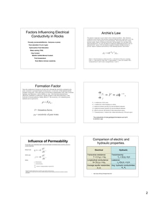
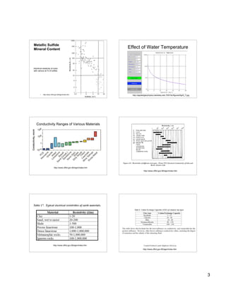
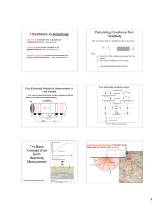
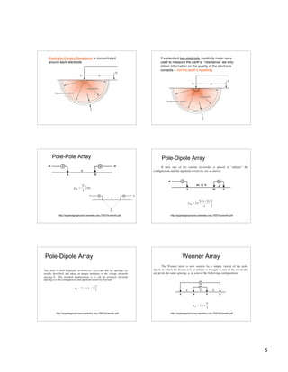


The document discusses electrical resistivity methods for measuring the resistivity of rocks. It defines key concepts like resistance, resistivity, and conductivity. Rock resistivity is influenced by factors like metallic sulfide content, porosity, clay content, pore saturation, and water salinity. Various electrode arrays like Wenner and Schlumberger are used to measure resistivity in the subsurface. Resistivity can provide information about rock properties and subsurface structures and fluids.


![DESIGN AND FABRICATION OF THE IBM 90-90 SEAT BELT CLAMP KIA VEHICLE[1].pptx 2...](https://cdn.slidesharecdn.com/ss_thumbnails/designandfabricationoftheibm90-90seatbeltclampkiavehicle1-260116160442-70ff67fc-thumbnail.jpg?width=640&height=640&fit=bounds)

