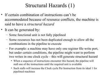
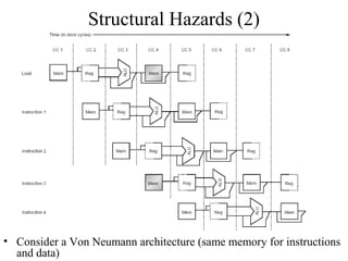
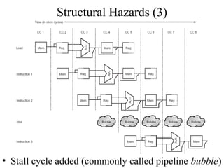
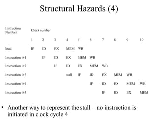
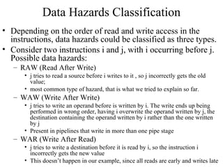
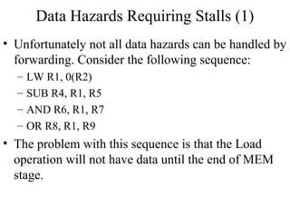
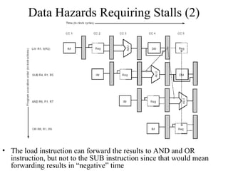
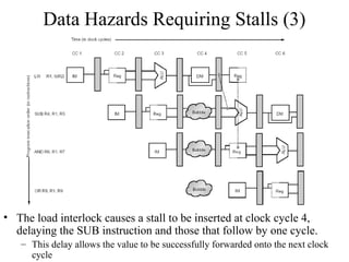
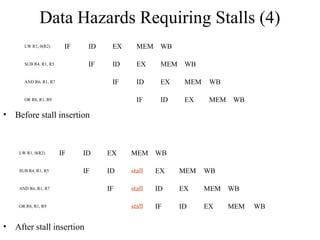
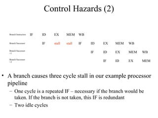
The document summarizes different types of pipeline hazards that can occur in a processor pipeline: structural hazards which occur due to limited hardware resources and prevent certain combinations of instructions from executing simultaneously; data hazards which occur when instructions depend on results of previous instructions in a way exposed by pipelining; and control hazards which occur due to pipelining of branches whose target may not be known until later in the pipeline. It describes techniques for handling these hazards such as forwarding, stalling, and instruction scheduling to minimize performance impacts.
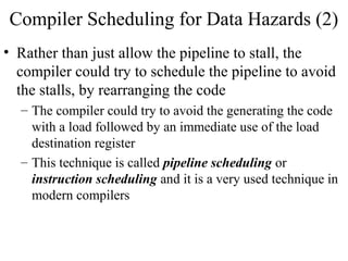
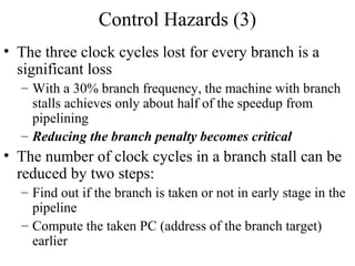
![Control Hazards (4)
Reducing the stall from branch hazards by moving the zero test and branch calculation into ID
phase of pipeline. It uses a separate adder to compute the branch target address during ID.
Because the branch target addition happens during ID, it will happen for all instructions. The
branch condition (Regs[IF/ID.IR6…10] op 0) will also be done for all instructions. The selection
of the sequential PC or the branch target PC will still occur during IF, but now it uses values
from ID phase, rather than from EX/MEM register. In this case, the branch instruction is done by
the end of ID phase, so EX, MEM and WB stages are not used for branch instructions anymore.](https://image.slidesharecdn.com/ct213processordesignpipelinehazard-130317101303-phpapp01/85/Ct213-processor-design_pipelinehazard-24-320.jpg)
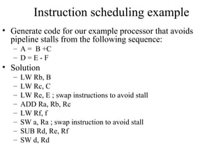
![Modified Pipelined Instruction Fetch
• Instruction Fetch
– IF/ID.IR mem[PC]
– IF/ID.NPC, PC if (Regs[IF/ID. IR6…10] op 0)
{IF/ID.NPC +(IF/ID.IR16)16##IF/ID.IR16…31}else{PC+4}
• Operation:
– send out the PC and fetch the instruction from memory
– Increment the PC by 4 to address the next instruction or
save the address generated by a taken branch of a
previous instruction in decode stage](https://image.slidesharecdn.com/ct213processordesignpipelinehazard-130317101303-phpapp01/85/Ct213-processor-design_pipelinehazard-25-320.jpg)
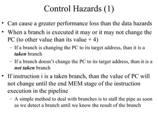
![Modified Pipelined Instruction Decode
• Instruction Decode Cycle/Register Fetch
– ID/EX.A Regs[IR6…10]; ID/EX.B Regs[IR11…15]
– ID/EX.IR IF/EX.IR
– ID/EX.Imm (IF/ID.IR16)16##IF/ID.IR16…31
– Compute the condition: Regs[IF/ID.IR6..10] op 0
– Compute the branch address: IF/ID.NPC + (IF/ID.IR16)16##IF/ID.IR16…31
• Operation
– Decode the instruction and access the register files to access the registers; the
output of the general purpose registers are read into two temporary register (A
and B, part of the pipeline registers ID/EX stage) for use in latter clock cycles
– The lower 16 bits of IR, stored in pipeline registers from IF/ID stage are also
sign extended and stored into temporary register Imm (part of ID/EX pipeline
registers), for latter use
– Value IR is passed to the next stage of pipeline registers (from IF/ID to ID/EX)
– Compute the values for the cond and branch target and use them to set the PC if
necessary (if taken branch)](https://image.slidesharecdn.com/ct213processordesignpipelinehazard-130317101303-phpapp01/85/Ct213-processor-design_pipelinehazard-26-320.jpg)