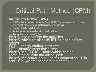
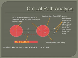
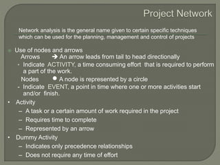
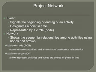
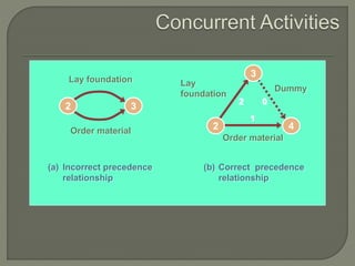
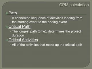
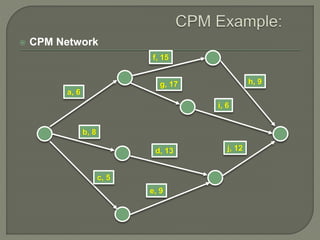
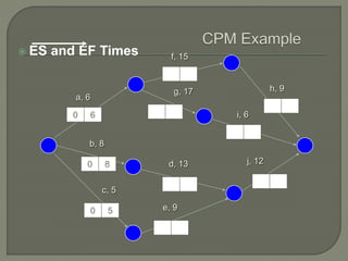
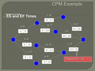
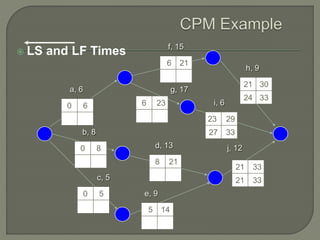
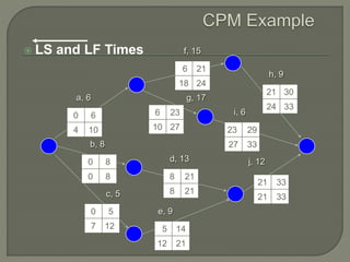
CPM Network Analysis
Prepared By :
Parth Desani
Civil Engineer
Critical Path Method (CPM)
Critical Path Analysis
Project Network
Concurrent Activities
Situations in network diagram
AOA & AON Project Networks for House
Network example
 Critical Path Method (CPM)
• E I Du Pont de Nemours & Co. (1957) for construction of new
chemical plant and maintenance shut-down
• Deterministic task times
• Activity-on-node network construction
• Repetitive nature of jobs
 Identify and prioritise the activities
 Identify which activities MUST be done before
others
 EST – identify earliest start time
 LFT – identify latest finish time
 Identify the FLOAT – tasks which can be
completed outside the critical path
 Identify the critical path – points connecting ESTs
and LFTs (where these are the same)
Nodes: Show the start and finish of a task
1 2
Node numbers showing order of
activities in the left hand semi-circle
of each node.
3
Earliest Start Time (EST)
5
Latest Finish Time (LFT)
A
3
B
5
Arrows
indicate the
order of the
tasks, the
letter above
shows the
order, the
time period
below the
arrow
The Critical Path
 Use of nodes and arrows
Arrows  An arrow leads from tail to head directionally
• Indicate ACTIVITY, a time consuming effort that is required to perform
a part of the work.
Nodes  A node is represented by a circle
- Indicate EVENT, a point in time where one or more activities start
and/or finish.
Network analysis is the general name given to certain specific techniques
which can be used for the planning, management and control of projects
• Activity
– A task or a certain amount of work required in the project
– Requires time to complete
– Represented by an arrow
• Dummy Activity
– Indicates only precedence relationships
– Does not require any time of effort
 Event
• Signals the beginning or ending of an activity
• Designates a point in time
• Represented by a circle (node)
 Network
• Shows the sequential relationships among activities using
nodes and arrows
Activity-on-node (AON)
nodes represent activities, and arrows show precedence relationships
Activity-on-arrow (AOA)
arrows represent activities and nodes are events for points in time
Project Network
2 3
Lay foundation
Order material
(a) Incorrect precedence
relationship
(b) Correct precedence
relationship
3
42
Dummy
Lay
foundation
Order material
1
2 0
A
B
C
A must finish before either B or C can start
A
B
C both A and B must finish before C can start
D
C
B
A
both A and C must finish before either of B or D can
start
A
C
B
D
Dummy
A must finish before B can start
both A and C must finish before D can start
darla/smbs/vit
9
3
2 0
1
3
1 1
1
1 2 4 6 7
3
5
Lay
foundation
Design house
and obtain
financing
Order and
receive
materials
Dummy
Finish
work
Select
carpet
Select
paint
Build
house
AON Project Network for House
1
3
2
2
4
3
3
1 5
1
6
1
7
1Start
Design house
and obtain
financing
Order and receive
materials
Select paint
Select carpet
Lay foundations Build house
Finish work
For clarity, this list is kept to a minimum by specifying only immediate relationships,
that is relationships involving activities that "occur near to each other in time".
The key question is: How long will it take to complete this project ?
 Is this a Start Activity?
 Is this a Finish Activity?
 What Activity Precedes this?
 What Activity Follows this?
 What Activity is Concurrent with this?
darla/smbs/vit
11
Path
• A connected sequence of activities leading from
the starting event to the ending event
Critical Path
• The longest path (time); determines the project
duration
Critical Activities
• All of the activities that make up the critical path
 CPM Network
a, 6
f, 15
b, 8
c, 5
e, 9
d, 13
g, 17 h, 9
i, 6
j, 12
 ES and EF Times
a, 6
f, 15
b, 8
c, 5
e, 9
d, 13
g, 17 h, 9
i, 6
j, 12
0 6
0 8
0 5
 ES and EF Times
a, 6
f, 15
b, 8
c, 5
e, 9
d, 13
g, 17 h, 9
i, 6
j, 12
0 6
0 8
0 5
5 14
8 21
6 23
6 21
 ES and EF Times
a, 6
f, 15
b, 8
c, 5
e, 9
d, 13
g, 17 h, 9
i, 6
j, 12
0 6
0 8
0 5
5 14
8 21 21 33
6 23
21 30
23 29
6 21
Project’s EF = 33
 LS and LF Times
a, 6
f, 15
b, 8
c, 5
e, 9
d, 13
g, 17
h, 9
i, 6
j, 12
0 6
0 8
0 5
5 14
8 21
21 33
6 23
21 30
23 29
6 21
21 33
27 33
24 33
 LS and LF Times
a, 6
f, 15
b, 8
c, 5
e, 9
d, 13
g, 17
h, 9
i, 6
j, 12
0 6
0 8
0 5
5 14
8 21
21 33
6 23
21 30
23 29
6 21
4 10
0 8
7 12
12 21
21 33
27 33
8 21
10 27
24 33
18 24
 Float
a, 6
f, 15
b, 8
c, 5
e, 9
d, 13
g, 17
h, 9
i, 6
j, 12
0 6
0 8
0 5
5 14
8 21 21 33
6 23
21 30
23 29
6 21
3 9
0 8
7 12
12 21
21 33
27 33
8 21
10 27
24 33
9 24
3 4
3
3
4
0
0
7
7
0
 Critical Path
darla/smbs/vit
20
a, 6
f, 15
b, 8
c, 5
e, 9
d, 13
g, 17 h, 9
i, 6
j, 12
CPM - Critical Path Method

CPM - Critical Path Method

  • 1.
    CPM Network Analysis PreparedBy : Parth Desani Civil Engineer
  • 2.
    Critical Path Method(CPM) Critical Path Analysis Project Network Concurrent Activities Situations in network diagram AOA & AON Project Networks for House Network example
  • 3.
     Critical PathMethod (CPM) • E I Du Pont de Nemours & Co. (1957) for construction of new chemical plant and maintenance shut-down • Deterministic task times • Activity-on-node network construction • Repetitive nature of jobs  Identify and prioritise the activities  Identify which activities MUST be done before others  EST – identify earliest start time  LFT – identify latest finish time  Identify the FLOAT – tasks which can be completed outside the critical path  Identify the critical path – points connecting ESTs and LFTs (where these are the same)
  • 4.
    Nodes: Show thestart and finish of a task 1 2 Node numbers showing order of activities in the left hand semi-circle of each node. 3 Earliest Start Time (EST) 5 Latest Finish Time (LFT) A 3 B 5 Arrows indicate the order of the tasks, the letter above shows the order, the time period below the arrow The Critical Path
  • 5.
     Use ofnodes and arrows Arrows  An arrow leads from tail to head directionally • Indicate ACTIVITY, a time consuming effort that is required to perform a part of the work. Nodes  A node is represented by a circle - Indicate EVENT, a point in time where one or more activities start and/or finish. Network analysis is the general name given to certain specific techniques which can be used for the planning, management and control of projects • Activity – A task or a certain amount of work required in the project – Requires time to complete – Represented by an arrow • Dummy Activity – Indicates only precedence relationships – Does not require any time of effort
  • 6.
     Event • Signalsthe beginning or ending of an activity • Designates a point in time • Represented by a circle (node)  Network • Shows the sequential relationships among activities using nodes and arrows Activity-on-node (AON) nodes represent activities, and arrows show precedence relationships Activity-on-arrow (AOA) arrows represent activities and nodes are events for points in time Project Network
  • 7.
    2 3 Lay foundation Ordermaterial (a) Incorrect precedence relationship (b) Correct precedence relationship 3 42 Dummy Lay foundation Order material 1 2 0
  • 8.
    A B C A must finishbefore either B or C can start A B C both A and B must finish before C can start D C B A both A and C must finish before either of B or D can start A C B D Dummy A must finish before B can start both A and C must finish before D can start
  • 9.
    darla/smbs/vit 9 3 2 0 1 3 1 1 1 12 4 6 7 3 5 Lay foundation Design house and obtain financing Order and receive materials Dummy Finish work Select carpet Select paint Build house AON Project Network for House 1 3 2 2 4 3 3 1 5 1 6 1 7 1Start Design house and obtain financing Order and receive materials Select paint Select carpet Lay foundations Build house Finish work
  • 10.
    For clarity, thislist is kept to a minimum by specifying only immediate relationships, that is relationships involving activities that "occur near to each other in time". The key question is: How long will it take to complete this project ?
  • 11.
     Is thisa Start Activity?  Is this a Finish Activity?  What Activity Precedes this?  What Activity Follows this?  What Activity is Concurrent with this? darla/smbs/vit 11
  • 12.
    Path • A connectedsequence of activities leading from the starting event to the ending event Critical Path • The longest path (time); determines the project duration Critical Activities • All of the activities that make up the critical path
  • 13.
     CPM Network a,6 f, 15 b, 8 c, 5 e, 9 d, 13 g, 17 h, 9 i, 6 j, 12
  • 14.
     ES andEF Times a, 6 f, 15 b, 8 c, 5 e, 9 d, 13 g, 17 h, 9 i, 6 j, 12 0 6 0 8 0 5
  • 15.
     ES andEF Times a, 6 f, 15 b, 8 c, 5 e, 9 d, 13 g, 17 h, 9 i, 6 j, 12 0 6 0 8 0 5 5 14 8 21 6 23 6 21
  • 16.
     ES andEF Times a, 6 f, 15 b, 8 c, 5 e, 9 d, 13 g, 17 h, 9 i, 6 j, 12 0 6 0 8 0 5 5 14 8 21 21 33 6 23 21 30 23 29 6 21 Project’s EF = 33
  • 17.
     LS andLF Times a, 6 f, 15 b, 8 c, 5 e, 9 d, 13 g, 17 h, 9 i, 6 j, 12 0 6 0 8 0 5 5 14 8 21 21 33 6 23 21 30 23 29 6 21 21 33 27 33 24 33
  • 18.
     LS andLF Times a, 6 f, 15 b, 8 c, 5 e, 9 d, 13 g, 17 h, 9 i, 6 j, 12 0 6 0 8 0 5 5 14 8 21 21 33 6 23 21 30 23 29 6 21 4 10 0 8 7 12 12 21 21 33 27 33 8 21 10 27 24 33 18 24
  • 19.
     Float a, 6 f,15 b, 8 c, 5 e, 9 d, 13 g, 17 h, 9 i, 6 j, 12 0 6 0 8 0 5 5 14 8 21 21 33 6 23 21 30 23 29 6 21 3 9 0 8 7 12 12 21 21 33 27 33 8 21 10 27 24 33 9 24 3 4 3 3 4 0 0 7 7 0
  • 20.
     Critical Path darla/smbs/vit 20 a,6 f, 15 b, 8 c, 5 e, 9 d, 13 g, 17 h, 9 i, 6 j, 12