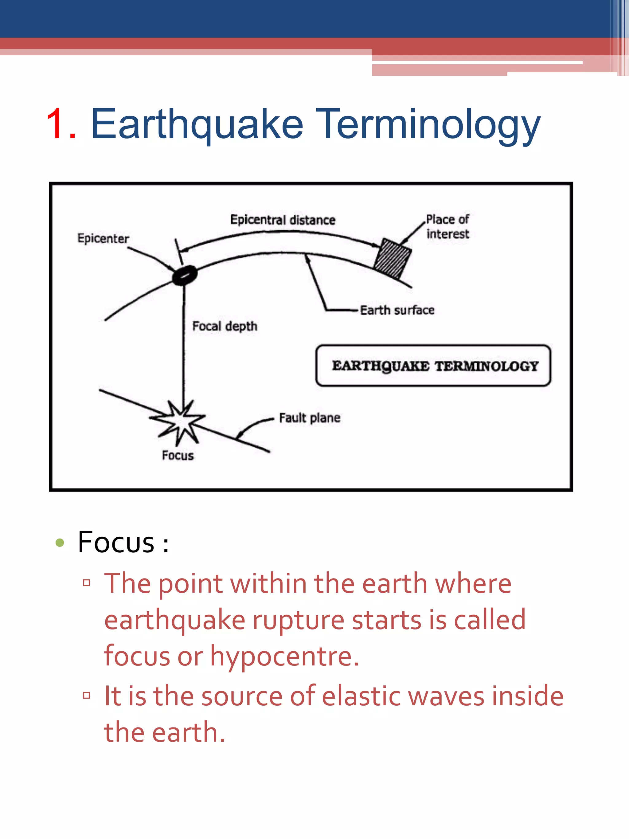
Earthquake
Engineering
Prepared By :
Parth Desani - 116470306049
INDEX
1. EarthquakeTerminology
2. Causes of Earthquake
3. Forecasting of Earthquake
4. Seismic zones of India
5. Classification of Earthquake
6. Factors affecting Earth Plate
7. Magnitude and intensity
8. Effects of earthquake
9. Principles of planning of buildings
10. Masonry construction aspects of
earthquake resistance
11. Earthquake resistant features
12. Repairing and Retrofication of
earthquake damaged structures
13. Suggestions for construction of new
masonry buildings in earthquake
sensitive areas
14. I.S. codes for earthquake resistant
design
1. Earthquake Terminology
• Focus :
▫ The point within the earth where
earthquake rupture starts is called
focus or hypocentre.
▫ It is the source of elastic waves inside
the earth.
• Epicentre :
▫ The point on the earth’s surface
vertically above the focus of the
earthquake is called epicentre.
• Focal depth :
▫ The depth of the focus from the
epicentre is called focal depth.
▫ It is an important parameter in
determining the damaging potential of
earthquake. Most of the damaging
earthquake have shallow focus with
focal depth less than 70 km.
• Epicentral distance :
▫ The distance from the epicentre to any
point if interest in the surface of the
earth is called epicentral distance or
focal distance.
• Foreshocks :
▫ A number of smaller size earthquake
take place before and after a big
earthquake.Those occuring before the
big one are called foreshocks.
• Aftershocks :
▫ Smaller size earthquakes occuring
after the mainshocks are cakked
aftershocks.
• Focal region :
▫ Seismic destruction propagates from
the focus through a limited region of
the surrounding earth’s body, which is
called the focal region.
• Isoseismal line :
▫ A contour or a line on a map joining points
of equal intensity for a particular
earthquake is called isoseismal line.
• Homoseismal line :
▫ The line joining location at which the
shock arrives simultaneiusly is known as
the homoseismal line.
• Meisoseismal :
▫ The region that suffers the strong shaking
and significant damage during earthquake
is termed as meisoseismal region.
▫ The region surrounding the epicentre is
the meisoseimal region.
• Aseismic :
▫ A fault on which no earthquake have been
observed is called aseismic.
• Earthquake :
▫ Momentary shaking of the ground or
vibration of the ground caused by the slip
or by volcanic or magnetic activity in the
earth are called earthquakes.
• Seismology :
▫ The science related with study of
earthquake and the structure of the earth,
is known as seismology. It includes the
study of seismic waves, origin, intensity of
earthquake, forecasting, etc.
• Seismicity :
▫ The geographic and historical distribution
of earthquakes is known as seismicity.
• Seismograph :
▫ A seismograph is an instrument used to
measure the vibration of the earth.
▫ It records earthquake ground motion in a
particular direction as a function of time.
• Seismogram :
▫ It is a record of seismograph in response to ground
motion produced by an earthquake.
▫ Seismogram is used for the following purpose :
 To determine epicentre of the earthquake.
 For obtaining the seismic parameters which are
used in design of structures and also for identifying
seismic zones.
 They also helps us in studying seismic waves and
their nature which helps in assessing the severity
of EQ.
• Seismoscope :
▫ This is a simple siesmograph that records
earthquakes ground motion on a paper without time
marks. Such instruments provide only the maximum
extent of motion during an earthquake.
• Seismometer :
▫ In the most modern seismograph an electric
transducer referred to as seismometer, senses the
motion and produces an analog electrical signal for
subsequent processing.
• Accelerometer :
▫ These are the instruments having
electronic transducers that produce an
output voltage proportional to ground
acceleration during earthquake, i.e. it
measures ground acceleration.
• Accelerogram :
▫ The motion of the ground can be
described in terms of displacement,
velocity or acceleration.The vibration of
ground acceleration with time recorded at
a point on ground during an earthquake is
called an acceleration.
• Displacement meter :
▫ The instrument that measures the
displacement of ground is known
displacement meter.
• Seismic gap :
▫ A section of a fault that has produced
earthquake in the past but is now quite, is
called seismic gap.
• Seismic zone :
▫ An area of similar seismic activities.
i.e.The Himalaya Zone.
• Earthquake size :
▫ Earthquake size is defined in terms of two
things :
 Magnitude
 Intensity
▫ Earthquake size is a measure of the
quantitative and qualitative effects of
vibration produced by the earthquake.
2. Causes of Earthquake
• Momentary shaking of the ground or
vibrations or oscillations of the ground
caused by the slip or by volcanic or
magmatic activity or other sudden
changes in the earth are called
earthquakes.
• Seismic Sources
Natural sources Man made sources
1.Tectonic earthquakes 1. Controlled sources
2.Volcanic earthquakes i. Chemical explosives
3. Plutonic earthquakes ii. Nuclear explosives
4. Land slides 2. Reservoir induced earthquakes
5. Collapse of cavity 3. Mining induced earthquakes
4. Cultural noise
( Industry,Traffic, etc.)
• Tectonic earthquake :
▫ The sudden release of strain energy by
rupture of the rock at plate boundry is the
primary cause of the seismic activity
around the world.
▫ About 90% of all earthquakes result from
tectonic events.
• Volcanic earthquake :
▫ Shallow volcanic earthquakes may result
from sudden shifting or movement of
magma.
• Plutonic earthquake :
▫ Plutonic earthquakes are caused by deep
seated changes.
• Land slides :
▫ Massive landslides associated with the
volcanic activity produce significant
ground motion.
3. Forecasting of
Earthquake• Natural calamities like heavy rain, flood,
cyclone, tsunami, etc. can be predicted in
advance. But, no scientific technique is
available for prediction of earthquake.
• The prediction of earthquake is almost
impossible.The scientists make prediction of
earthquake based on various analysis and
assumption.
• Various predictions are :
▫ From the study of location of past earthquake,
intensity, time duration, geological condition, etc.
▫ Abrupt change in waterl level in ponds, lakes, etc.
▫ From the study of changes in ground water level
▫ From ground tilting study
▫ From the study of main shocks, fore shocks, after
shocks.
▫ Ground slope changes
▫ Increase in volume of rocks, level of random gas
level in deep wells and in electric conductivity of
rocks.
▫ From strange behavior of animals and birds.
• Latest technique for earthquake
forecasting :
▫ All the seismograph stations can be
connected to on line data collection
system and by using computer digital
seismograph may be connected toV-set
system to warn people few seconds in
advance of earthquake.
▫ There are three types of earthquake
waves, namely P-waves, S-waves and
surface waves.
• P-waves are the fastest having speed
6 km/s, S-waves 3.5 km/s and surface
waves 2 km/s.
• P-waves reach the seismograph
station first, while surface waves
being slowest reach at last.The
surface waves are the most
destructing waves.
• If emergency alarm is attached to the
forecasting system, it can warn the
people few seconds in advance to
escape out of their houses.This type
of system is already working in Japan
and USA.
• Strong Ground Motion :
▫ Shaking of ground on earth’s surface is a net
consequence of motion, vertical and
horizontal, caused by seismic waves
generated by energy release at each material
point within the three dimensional volume
that ruptures at the fault.These waves arrives
at various instant of time, have different
amplitudes and carry different levels of
energy.Thus, the motion at any site on
ground is random in nature with its amplitude
and direction varying randomly with time.
▫ Large earthquakes at great distances can
produce weak motion that may not damage
structures or even felt by humans. But,
sensitive instrument can record these.This
makes it possible to locate distant
earthquake. However, from engineering
viewpoint, strong motions that can possibly
damage structures are of interest.This can
happen with earthquakes in the vicinity or
even with large earthquakes at reasonable
medium to large distances.
• Characteristics to strong ground
motion :
▫ The motion of the ground can be
described in terms of displacement,
velocity or acceleration.The variation
of ground acceleration with time
recorded at a point on ground during
an earthquake is called an
accelerogram.The ground velocity and
displacement can be obtained by direct
integration of an acceleration.
▫ The nature of accelerograms may vary
depending on energy released at
source, type of slip at fault rupture,
geology along the travel path from
fault rupture to the earth’s surface, and
local soil.
• These accelerograms carry distinct in
formation regarding ground shaking
like,
▫ Peak amplitude
▫ Duration of strong shaking
▫ Frequency content
▫ Energy content
• These characteristics of strong motion
in the vicinity of causative fault is
strongly dependent on the nature of
faulting.The motion depends on source
parameters such as fault shape, its area,
maximum fault dislocation, stress drop
and distance of fault plane from ground
surface.
• The elastic properties of the material
through which the seismic waves travel,
also influence the strong motion.
• The amplitude of ground acceleration
decreases with increasing distance from
the causative fault in general.
4. Seismic zones of India
• Basic Geography andTectonic features :
▫ India lies at the northwestern end of the
Indo-Australian plate, which
encompasses India, Australia, a major
portion of the Indian ocean and other
smaller countries.
▫ This plate is colliding against the huge
Eurasian plate and going under the
Eurasian plate; this process of one
tectonic plate getting under another is
called subduction.
▫ A seaTethys, separated these plates
before they collided. Part of the
lithosphere, the earth’s crust, is covered
by oceans and the rest by the continents.
Due to this subduction process, the great
Himalayas rising about 2.5 cm per year.
• Three chief tectonic sub-region of India are
the mighty Himalayas along the north, the
plains of the Ganges and other rivers, and
the Peninsula.
• The Himalayas consist primarily of
sediments accumulated over long
geological time in theTethys.
• The Indo-Gangetic basin with deep
alluvium is a great depression caused by
the local of the Himalayas on the
continent.The peninsular part of the
country consist of ancient rocks deformed
in the past Himalayas – like collisions.
• Before the Himalayan collision, several
tens of millions of years ago, lava flowed
across the central part of peninsular India
leaving layers of basalt rock.Coastal areas
like Kachchh show marine deposits
testifying to submerged under the sea
millions of years ago.
• Need for seismic zoning :
▫ A number of significant earthquakes have
occurred in and around India over the past
century. Some of these occurred in
populated urban areas and hence caused
great damage. Many went unnoticed, as
they occurred deep under the earth’s
surface or in relatively un-inhabitated
place. Most earthquake occur along the
Himalayan plate boundry but a number of
earthquake have also occurred in the
Peninsular region.
▫ The varying geology at different locations
in the country implies that the likelihood
of damaging earthquakes taking place at
different locations is different.Thus, a
seismic zones map is required to identify
these regions. Based on the levels of
intensities sustained during damaging
past earthquakes, the 1970 version of the
zone map subdivided India into five zones
– I, II, III, IV &V.
▫ The maximum Modified Mercalli
(MM) intensity of seismic shaking,
expected in these zones wereV or
less,VI,VII,VIII and IX and higher
respectively. Parts of Himalayan
boundry in the north and northest
and the Kachchh area in the west
were classified as zoneV.
▫ The seismic zone maps are revised
from time to time as more
understanding is gained on the
geology, the seismotectonics and the
seismic activity in the country.The
Indian standards provided the first
seismic zone map in 1962, which was
later revised in 1967 and again in
1970.
▫ The map has been revised again in
2002, and it now has only four seismic
zones – II, III, IV, andV.
▫ Zone – I has been merged into zone –
II.
▫ Madras which was earlier in zone – II
has been included in zone – III.
▫ Revised seismic zone map has been
given in IS : 1893 (part – I) – 2002 and
reproduced here above fig.
• Imported cities situated in zone –V :
▫ Bhuj, Imphal, Guwahati, Kohima,
Tezpur, Mandi, Srinagar, Darbhanga
• Imported cities situated in zone – IV :
▫ Delhi, Amritsar, Ambala, Chandigarh,
Patna, Simla, Ludhiyana, Roorkee
5. Classification of
Earthquake
• The various basis of classification of
earthquakes are as under :
a) Based on location :
Based on location the earthquake are
classified as,
1. Interplate earthquake :
 Most earthquake in the world
occur along the boundaries of the
tectonic plated and are called
interplate earthquakes.
About 99 % earthquakes are interplate
earthquakes.
e.g. 1897 – Assam earthquake
1905 – Kangra (H.P.)
1950 – Assam earthquake
2. Intraplate earthquake :
 A number of earthquakes also occur
within the plate itself away from the plate
boundaries, are called intraplate
earthquake.
 About 1% earthquakes are intraplate
earthquakes.
 e.g. 1993 – Lature earthquake
1967 – Koyna earthquake
b) Based on focal depth :
Based on focal depth the earthquakes are
classified as below :
Earthquake Focal depth
Shallow earthquake < 70 km
Mediam earthquake 70 to 300 km
Deep earthquake >300 km
c) Based on size or Magnitude :
Earthquake are often classified into
different groups based on their size as
given in table below :
Group Magnitude
Annual Average
Number
Great 8 and higher 1
Major 7 – 7.9 18
Strong 6 - 6.9 120
Moderate 5 – 5.9 800
Light 4 – 4.9 6200 (estimated)
Minor 3 – 3.9 49000 (estimated)
Very minor < 3.9
M2.3 – 1000/day,
M1.2 – 8000/day
d) Based on epicentral distance :
Based on epicentral distance, the
earthquakes are classified as under :
1. Local earthquake - < 1°
2. Regional earthquake – 1° – 10°
3.Teleseismic earthquake - > 10°
6. Factors affecting earth
plate
a) Internal Factors :
▫ Movements of lava below earth crust
▫ Vapour pressure
▫ Movement of tectonic plates
▫ Processes between rocks
b) External factors :
▫ Effects of air, water, sunlight
▫ Attraction of moon and son on the earth
▫ Changes in atmospheric moisture
▫ Increase in difference between
minimum and maximum atmospheric
temperature
▫ Atmospheric changes like extreme cold,
fog, odd season rainfall, etc.
▫ Cyclonic effect
▫ Changes in rise and set timings for the
sun
▫ Irregular monsoons
▫ Global warming
▫ Changes in sea water level, etc.
7. Magnitude and Intensity
Magnitude Intensity
1. Magnitude of an
earthquake is a
measure of amount
of energy released
during and
earthquake.
2. It is the
quantitative
measure of the
actual size of the
earthquake.
3. For a particular
earthquake
magnitude is same
for all the places.
4. It is more precise
measure of
earthquake.
1. The intensity of
earthquake is a
measure of the
actual ground
shaking at a
location during an
earthquake.
2. It is the qualitative
measure of the
size if the
earthquake.
3. For a particular
earthquake
intensity of
earthquake
decreases with
distance from the
epicenter.
4. It is less precise
than magnitude
8. Effects of earthquake
Primary effects
Secondary effects
• Primary Effects :
• Effects related with origin of earthquake
are known as primary effects. Primary
effects are directly connected with
geology and topography.
• Primary effects are :
• Change in topography
• Formation of new hills
• Change in direction of existing water course
• Formation of new water course
• Wrapping of strata
• Formation of sand dyke
• Formation of huge cracks in land
• Change in under ground water level
• Secondary Effects :
▫ Secondary effects are caused due to
passage of seismic waves and are
associated with ground shaking.
▫ Secondary effects are :
 Destruction of human lives
 Destruction of multistoried buildings
 Destruction of dams and bridges
 Landslides and mudslides
 Uprooting of trees
 Psychological effects on human beings
 Worst effect on communication system
 Damage to road and railway lines
 Destruction of telephone andTV tower
 Huge waves in the sea (Tsunami)
 Fire by damaging gas lines and snapping
electric wires
 Rupture of damage and levees causing
floods
 Liquefaction of soil and sinking of structure
9. Principles of planning of
buildings
• Building configurations :
Configuration requirements of a structure :
• From a planner point of view, as a
precursor to the design analysis, the
configuration requirements preferred as far
as possible are listed below.
• The structure should,
 Be simple and symmetrical.
 Be not too elongated in plan or elevation.
 Have uniform and continuous distribution of
strength, mass and stiffness, so that centre
of mass and centre of stiffness are close to
each other.
 Be without re-entrant corners.
 Have sufficient ductility.
 Be preferably without large projections.
 Be without external elevator shafts and
staircase wells as they are undesirable and
tend to act on their own in earthquakes.
 Have horizontal members which form hinges
before the vertical members.
 Have stiffness related to the soil properties.
• Effects of irregularities :
▫ The most important cause of damage
of RC building configuration. A building
that lacks symmetry and has
discontinuity in geometry, mass or
load resisting members is called a
irregular building.The irregularity in a
building result in obstruction to flow of
inertia forces and cause a lot of
damage to the building. Similarly, a
symmetry of buildings causes large
torsional moments resulting in
damage to the structure.
▫ The irregularities in a building are of
two types :
 Vertical Irregularities
 Horizontal Irregularities
• Vertical irregularities :
▫ Irregularity in stiffness and strength
▫ Floating columns
▫ Mass irregularities
▫ Vertical geometric irregularities
• Horizontal Irregularities :
▫ These irregularities are caused due to :
 Asymmetrical plan shapes
 Re-entrant corners
 Cut – out (Large openings)
 Non – parallel system
10. Masonry construction
aspects of earthquake
resistance
• Plan of building :
▫ Shape of building should be easy and
symmetry. If the shape is not
symmetry earthquake can produces
torsion.
▫ Place and size should be also
symmetry of doors and windows.
▫ Earthquake resistivity of a simple
rectangular building is more.
▫ In plan projection in particular
directions should nor be more than L/3
or B/3.
▫ Length of block should not more than
3B.
▫ Divide large buildings into small blocks
by placing 30 to 40 mm separation
joints, which can act as expansion
joints.
• Masonry Mortar :
Category Range of αh
A 0.04 to less than 0.05
B 0.05 to 0.06 (both inclusive)
C More than 0.06 but less than 0.08
D 0.08 to less than 0.12
E More than 0.12
Category Proportion of ingredients
A
M2 (cement – sand 1:6) or M3 (lime – cinder 1:3)
or richer
B, C
M2 (cement – lime sand 1:2:9 or cement – sand
1:6) or richer
D, E
H2 (cement – sand 1:4) or M1 (cement – lime
sand 1:1:6) or richer
• Wall dimension and building height :
▫ Wall thickness of 1 storey building
should net be more than 1 brick (190
mm).
▫ In 3 storey building wall thickness of
ground floor should be at least 1 ½
brick and wall thickness of top floor
should be at least 1 brick.
▫ Wall thickness should be more than
1/16 times of total length between two
cross walls.
▫ The masonry bearing walls can be built
up to a maximum of 4 storeys.
• Wall opening :
▫ Opening in wall should be small and at
center.
▫ Opening from internal corners should
be at ¼ height or opening, which
should not be less than 60 cm.
▫ Opening should not be more than,
 1 storey = length of wall between two
cross wall 50 %
 2 storey = 42 %
 3 storey = 33 %
▫ Horizontal distance between two
openings, should not less than half of
height of short opening or 60 cm.
▫ Vertical distance should not less than
half of width of short opening or 60
cm.
▫ When the given criteria about
openings are not followed, secure it by
placing 2 diameter bars.
• b1 + b2 + b3 < 0.5 l1 for one storey,
0.42 l1 for two storey,
0.33 l1 for three storey
• b6 + b7 < 0.5 l2 for one storey,
0.42 l2 for two storey,
0.33 l2 for three storey
• b4 > 0.5 h2 but not less than 60 cm.
• b5 > 0.25 h1 but not less than 60 cm.
• h3 > 60 cm or 0.51 b2 or b9 whichever
is more.
11. Earthquake Resistant
Features
• Horizontal Reinforcement in Walls :
▫ Horizontal Bands :
 Horizontal bands are the most
important earthquake – resistant
feature in masonry buildings.The bands
are provided to hold a masonry building
as a single unit by typing all the walls
together, and are similar to 4 closet belt
provided around cardboard boxes.
 These bands are provided continuous
through all the load bearing walls at
plinth, lintel, roof and gable level.
1. Plinth band :
Where the soil is soft or includes
irregular properties, plinth band is
required. It also works as D.P.C.
2. Lintel band :
This is more important band, which is
required in all walls at lintel level.
3. Roof band :
Roof band can be provided at the
instant below to the R.C.C. roof or
floor.
4. Gable band :
The triangle portion of gable end of
masonry can be considered as gable
band.
• Sections and reinforcement of bands :
▫ Grade of concrete should not less than
M15.
▫ Thickness of should be more than 75
cm.
▫ Two longitudinal bars of 8 mm diameter
and lateral ties at 6 mm diameter @ 150
mm c/c should be placed.
▫ Dowel bars at corners and junctoins :
 As a suppliment to the bands, steel
dowel bars may be used at corners andT
– junctions to integrate the box action
of walls.
 Dowel bars are placed in every fourth
course, or at about 50 cm intervals and
taken into the walls to sufficient length
so as to provide full bond strength.
 As an alternative, strengthening ofT –
junction and corner can be done by
introducing wire mesh.These bars must
be laid in 1:3 cement-sand-mortar with
a minimum cover of 10mm.
▫ Vertical reinforcement in walls :
12. Repairing and
Retrofication of Earthquake
damaged structure
• Repair, Restoration and Retrofication :
• Repair :
▫ Service the non-structural damages
like cracks and surface finishing after
the earthquake is called repairing
• Restoration :
▫ Gain the strength of structures after
damaging due to earthquake is called
restoration.
▫ Restrengthening can be done by using
epoxy resin, crack filling by injection,
cement mortar, etc.
• Retrofication :
▫ The strengthening process of structure
through it structure can resist future
earthquakes is called retrofication.
• Enlistment of checking earthquake
damaged structure :
▫ Column and beam at corner
▫ Column and beam at outside
▫ Expanded cantilever, balcony
▫ Wall and column of stair and lift
▫ Upper storied column, beam and its
joints
▫ Water tank, partition wall, filler wall
▫ Drainage connection, water
connection and electricity connection.
13. Suggestions for new
construction in earthquake
sensitive areas
Appoint only licensed engineer for
construction work
Check the maximum bearing capacity of
soil before starting the foundation
Take suggestions of experts before start
work in fine sand, black cotton soil
Prefer the rectangle shape of building
Use light weight materials for roofing
work
Thickness of load transfer wall should not
less than 23 cm
Use the materials as per IS criteria. If
possible choose branded materials and
tested materials for work
The cement sand mortar proportion
should not less than 1:4
Use bricks with minimum compressive
strength of 35 kg/sq.cm
Building should be of 4-5 stories, which
height should not be more than 15 m
To strength the walls use reinforcement
Space for door – window and opening
keep less as possible
Prefer framed structure in place of load
bearing structure
Construct shear walls in multi-storied
buildings
Provide expansion joints in large
buildings
Provide R.C.C. bands at plinth level, sill
level, lintel level and roof level
14. I.S. codes for
Earthquake resistant
design
• IS 1893-1984, criteria for EQ resist
design of structures IS 1893-Part I-2002
• IS 4326-1993, EQ resistant design and
construction of building
• IS 13827-1993, Improving EQ resistance
of earthen buildings
• IS 13828-1993, Improving EQ resistance
of masonry buildings
• IS 13920-1993, Ductility, Detailing or
Reinforced Concrete subject to seismic
forces
• IS 13295-1993, Repair and Seismic
strengthening of buildings
• SP 22-1982, Explantory handbook on
codes for EQ engineering
Earthquake engineering

Earthquake engineering

  • 1.
  • 2.
    INDEX 1. EarthquakeTerminology 2. Causesof Earthquake 3. Forecasting of Earthquake 4. Seismic zones of India 5. Classification of Earthquake 6. Factors affecting Earth Plate 7. Magnitude and intensity 8. Effects of earthquake 9. Principles of planning of buildings 10. Masonry construction aspects of earthquake resistance 11. Earthquake resistant features 12. Repairing and Retrofication of earthquake damaged structures 13. Suggestions for construction of new masonry buildings in earthquake sensitive areas 14. I.S. codes for earthquake resistant design
  • 3.
    1. Earthquake Terminology •Focus : ▫ The point within the earth where earthquake rupture starts is called focus or hypocentre. ▫ It is the source of elastic waves inside the earth.
  • 4.
    • Epicentre : ▫The point on the earth’s surface vertically above the focus of the earthquake is called epicentre. • Focal depth : ▫ The depth of the focus from the epicentre is called focal depth. ▫ It is an important parameter in determining the damaging potential of earthquake. Most of the damaging earthquake have shallow focus with focal depth less than 70 km. • Epicentral distance : ▫ The distance from the epicentre to any point if interest in the surface of the earth is called epicentral distance or focal distance.
  • 5.
    • Foreshocks : ▫A number of smaller size earthquake take place before and after a big earthquake.Those occuring before the big one are called foreshocks. • Aftershocks : ▫ Smaller size earthquakes occuring after the mainshocks are cakked aftershocks. • Focal region : ▫ Seismic destruction propagates from the focus through a limited region of the surrounding earth’s body, which is called the focal region.
  • 6.
    • Isoseismal line: ▫ A contour or a line on a map joining points of equal intensity for a particular earthquake is called isoseismal line. • Homoseismal line : ▫ The line joining location at which the shock arrives simultaneiusly is known as the homoseismal line. • Meisoseismal : ▫ The region that suffers the strong shaking and significant damage during earthquake is termed as meisoseismal region. ▫ The region surrounding the epicentre is the meisoseimal region. • Aseismic : ▫ A fault on which no earthquake have been observed is called aseismic.
  • 7.
    • Earthquake : ▫Momentary shaking of the ground or vibration of the ground caused by the slip or by volcanic or magnetic activity in the earth are called earthquakes. • Seismology : ▫ The science related with study of earthquake and the structure of the earth, is known as seismology. It includes the study of seismic waves, origin, intensity of earthquake, forecasting, etc. • Seismicity : ▫ The geographic and historical distribution of earthquakes is known as seismicity. • Seismograph : ▫ A seismograph is an instrument used to measure the vibration of the earth. ▫ It records earthquake ground motion in a particular direction as a function of time.
  • 8.
    • Seismogram : ▫It is a record of seismograph in response to ground motion produced by an earthquake. ▫ Seismogram is used for the following purpose :  To determine epicentre of the earthquake.  For obtaining the seismic parameters which are used in design of structures and also for identifying seismic zones.  They also helps us in studying seismic waves and their nature which helps in assessing the severity of EQ. • Seismoscope : ▫ This is a simple siesmograph that records earthquakes ground motion on a paper without time marks. Such instruments provide only the maximum extent of motion during an earthquake. • Seismometer : ▫ In the most modern seismograph an electric transducer referred to as seismometer, senses the motion and produces an analog electrical signal for subsequent processing.
  • 9.
    • Accelerometer : ▫These are the instruments having electronic transducers that produce an output voltage proportional to ground acceleration during earthquake, i.e. it measures ground acceleration. • Accelerogram : ▫ The motion of the ground can be described in terms of displacement, velocity or acceleration.The vibration of ground acceleration with time recorded at a point on ground during an earthquake is called an acceleration.
  • 10.
    • Displacement meter: ▫ The instrument that measures the displacement of ground is known displacement meter. • Seismic gap : ▫ A section of a fault that has produced earthquake in the past but is now quite, is called seismic gap. • Seismic zone : ▫ An area of similar seismic activities. i.e.The Himalaya Zone. • Earthquake size : ▫ Earthquake size is defined in terms of two things :  Magnitude  Intensity ▫ Earthquake size is a measure of the quantitative and qualitative effects of vibration produced by the earthquake.
  • 11.
    2. Causes ofEarthquake • Momentary shaking of the ground or vibrations or oscillations of the ground caused by the slip or by volcanic or magmatic activity or other sudden changes in the earth are called earthquakes. • Seismic Sources Natural sources Man made sources 1.Tectonic earthquakes 1. Controlled sources 2.Volcanic earthquakes i. Chemical explosives 3. Plutonic earthquakes ii. Nuclear explosives 4. Land slides 2. Reservoir induced earthquakes 5. Collapse of cavity 3. Mining induced earthquakes 4. Cultural noise ( Industry,Traffic, etc.)
  • 12.
    • Tectonic earthquake: ▫ The sudden release of strain energy by rupture of the rock at plate boundry is the primary cause of the seismic activity around the world. ▫ About 90% of all earthquakes result from tectonic events. • Volcanic earthquake : ▫ Shallow volcanic earthquakes may result from sudden shifting or movement of magma. • Plutonic earthquake : ▫ Plutonic earthquakes are caused by deep seated changes. • Land slides : ▫ Massive landslides associated with the volcanic activity produce significant ground motion.
  • 13.
    3. Forecasting of Earthquake•Natural calamities like heavy rain, flood, cyclone, tsunami, etc. can be predicted in advance. But, no scientific technique is available for prediction of earthquake. • The prediction of earthquake is almost impossible.The scientists make prediction of earthquake based on various analysis and assumption. • Various predictions are : ▫ From the study of location of past earthquake, intensity, time duration, geological condition, etc. ▫ Abrupt change in waterl level in ponds, lakes, etc. ▫ From the study of changes in ground water level ▫ From ground tilting study ▫ From the study of main shocks, fore shocks, after shocks. ▫ Ground slope changes ▫ Increase in volume of rocks, level of random gas level in deep wells and in electric conductivity of rocks. ▫ From strange behavior of animals and birds.
  • 14.
    • Latest techniquefor earthquake forecasting : ▫ All the seismograph stations can be connected to on line data collection system and by using computer digital seismograph may be connected toV-set system to warn people few seconds in advance of earthquake. ▫ There are three types of earthquake waves, namely P-waves, S-waves and surface waves.
  • 15.
    • P-waves arethe fastest having speed 6 km/s, S-waves 3.5 km/s and surface waves 2 km/s. • P-waves reach the seismograph station first, while surface waves being slowest reach at last.The surface waves are the most destructing waves. • If emergency alarm is attached to the forecasting system, it can warn the people few seconds in advance to escape out of their houses.This type of system is already working in Japan and USA.
  • 16.
    • Strong GroundMotion : ▫ Shaking of ground on earth’s surface is a net consequence of motion, vertical and horizontal, caused by seismic waves generated by energy release at each material point within the three dimensional volume that ruptures at the fault.These waves arrives at various instant of time, have different amplitudes and carry different levels of energy.Thus, the motion at any site on ground is random in nature with its amplitude and direction varying randomly with time. ▫ Large earthquakes at great distances can produce weak motion that may not damage structures or even felt by humans. But, sensitive instrument can record these.This makes it possible to locate distant earthquake. However, from engineering viewpoint, strong motions that can possibly damage structures are of interest.This can happen with earthquakes in the vicinity or even with large earthquakes at reasonable medium to large distances.
  • 17.
    • Characteristics tostrong ground motion : ▫ The motion of the ground can be described in terms of displacement, velocity or acceleration.The variation of ground acceleration with time recorded at a point on ground during an earthquake is called an accelerogram.The ground velocity and displacement can be obtained by direct integration of an acceleration. ▫ The nature of accelerograms may vary depending on energy released at source, type of slip at fault rupture, geology along the travel path from fault rupture to the earth’s surface, and local soil.
  • 18.
    • These accelerogramscarry distinct in formation regarding ground shaking like, ▫ Peak amplitude ▫ Duration of strong shaking ▫ Frequency content ▫ Energy content • These characteristics of strong motion in the vicinity of causative fault is strongly dependent on the nature of faulting.The motion depends on source parameters such as fault shape, its area, maximum fault dislocation, stress drop and distance of fault plane from ground surface. • The elastic properties of the material through which the seismic waves travel, also influence the strong motion. • The amplitude of ground acceleration decreases with increasing distance from the causative fault in general.
  • 19.
  • 20.
    • Basic GeographyandTectonic features : ▫ India lies at the northwestern end of the Indo-Australian plate, which encompasses India, Australia, a major portion of the Indian ocean and other smaller countries. ▫ This plate is colliding against the huge Eurasian plate and going under the Eurasian plate; this process of one tectonic plate getting under another is called subduction. ▫ A seaTethys, separated these plates before they collided. Part of the lithosphere, the earth’s crust, is covered by oceans and the rest by the continents. Due to this subduction process, the great Himalayas rising about 2.5 cm per year.
  • 21.
    • Three chieftectonic sub-region of India are the mighty Himalayas along the north, the plains of the Ganges and other rivers, and the Peninsula. • The Himalayas consist primarily of sediments accumulated over long geological time in theTethys. • The Indo-Gangetic basin with deep alluvium is a great depression caused by the local of the Himalayas on the continent.The peninsular part of the country consist of ancient rocks deformed in the past Himalayas – like collisions. • Before the Himalayan collision, several tens of millions of years ago, lava flowed across the central part of peninsular India leaving layers of basalt rock.Coastal areas like Kachchh show marine deposits testifying to submerged under the sea millions of years ago.
  • 22.
    • Need forseismic zoning : ▫ A number of significant earthquakes have occurred in and around India over the past century. Some of these occurred in populated urban areas and hence caused great damage. Many went unnoticed, as they occurred deep under the earth’s surface or in relatively un-inhabitated place. Most earthquake occur along the Himalayan plate boundry but a number of earthquake have also occurred in the Peninsular region. ▫ The varying geology at different locations in the country implies that the likelihood of damaging earthquakes taking place at different locations is different.Thus, a seismic zones map is required to identify these regions. Based on the levels of intensities sustained during damaging past earthquakes, the 1970 version of the zone map subdivided India into five zones – I, II, III, IV &V.
  • 23.
    ▫ The maximumModified Mercalli (MM) intensity of seismic shaking, expected in these zones wereV or less,VI,VII,VIII and IX and higher respectively. Parts of Himalayan boundry in the north and northest and the Kachchh area in the west were classified as zoneV. ▫ The seismic zone maps are revised from time to time as more understanding is gained on the geology, the seismotectonics and the seismic activity in the country.The Indian standards provided the first seismic zone map in 1962, which was later revised in 1967 and again in 1970.
  • 24.
    ▫ The maphas been revised again in 2002, and it now has only four seismic zones – II, III, IV, andV. ▫ Zone – I has been merged into zone – II. ▫ Madras which was earlier in zone – II has been included in zone – III. ▫ Revised seismic zone map has been given in IS : 1893 (part – I) – 2002 and reproduced here above fig. • Imported cities situated in zone –V : ▫ Bhuj, Imphal, Guwahati, Kohima, Tezpur, Mandi, Srinagar, Darbhanga • Imported cities situated in zone – IV : ▫ Delhi, Amritsar, Ambala, Chandigarh, Patna, Simla, Ludhiyana, Roorkee
  • 25.
    5. Classification of Earthquake •The various basis of classification of earthquakes are as under : a) Based on location : Based on location the earthquake are classified as, 1. Interplate earthquake :  Most earthquake in the world occur along the boundaries of the tectonic plated and are called interplate earthquakes. About 99 % earthquakes are interplate earthquakes. e.g. 1897 – Assam earthquake 1905 – Kangra (H.P.) 1950 – Assam earthquake
  • 26.
    2. Intraplate earthquake:  A number of earthquakes also occur within the plate itself away from the plate boundaries, are called intraplate earthquake.  About 1% earthquakes are intraplate earthquakes.  e.g. 1993 – Lature earthquake 1967 – Koyna earthquake b) Based on focal depth : Based on focal depth the earthquakes are classified as below : Earthquake Focal depth Shallow earthquake < 70 km Mediam earthquake 70 to 300 km Deep earthquake >300 km
  • 27.
    c) Based onsize or Magnitude : Earthquake are often classified into different groups based on their size as given in table below : Group Magnitude Annual Average Number Great 8 and higher 1 Major 7 – 7.9 18 Strong 6 - 6.9 120 Moderate 5 – 5.9 800 Light 4 – 4.9 6200 (estimated) Minor 3 – 3.9 49000 (estimated) Very minor < 3.9 M2.3 – 1000/day, M1.2 – 8000/day
  • 28.
    d) Based onepicentral distance : Based on epicentral distance, the earthquakes are classified as under : 1. Local earthquake - < 1° 2. Regional earthquake – 1° – 10° 3.Teleseismic earthquake - > 10°
  • 29.
    6. Factors affectingearth plate a) Internal Factors : ▫ Movements of lava below earth crust ▫ Vapour pressure ▫ Movement of tectonic plates ▫ Processes between rocks b) External factors : ▫ Effects of air, water, sunlight ▫ Attraction of moon and son on the earth ▫ Changes in atmospheric moisture ▫ Increase in difference between minimum and maximum atmospheric temperature ▫ Atmospheric changes like extreme cold, fog, odd season rainfall, etc. ▫ Cyclonic effect ▫ Changes in rise and set timings for the sun ▫ Irregular monsoons ▫ Global warming ▫ Changes in sea water level, etc.
  • 30.
    7. Magnitude andIntensity Magnitude Intensity 1. Magnitude of an earthquake is a measure of amount of energy released during and earthquake. 2. It is the quantitative measure of the actual size of the earthquake. 3. For a particular earthquake magnitude is same for all the places. 4. It is more precise measure of earthquake. 1. The intensity of earthquake is a measure of the actual ground shaking at a location during an earthquake. 2. It is the qualitative measure of the size if the earthquake. 3. For a particular earthquake intensity of earthquake decreases with distance from the epicenter. 4. It is less precise than magnitude
  • 31.
    8. Effects ofearthquake Primary effects Secondary effects • Primary Effects : • Effects related with origin of earthquake are known as primary effects. Primary effects are directly connected with geology and topography. • Primary effects are : • Change in topography • Formation of new hills • Change in direction of existing water course • Formation of new water course • Wrapping of strata • Formation of sand dyke • Formation of huge cracks in land • Change in under ground water level
  • 32.
    • Secondary Effects: ▫ Secondary effects are caused due to passage of seismic waves and are associated with ground shaking. ▫ Secondary effects are :  Destruction of human lives  Destruction of multistoried buildings  Destruction of dams and bridges  Landslides and mudslides  Uprooting of trees  Psychological effects on human beings  Worst effect on communication system  Damage to road and railway lines  Destruction of telephone andTV tower  Huge waves in the sea (Tsunami)  Fire by damaging gas lines and snapping electric wires  Rupture of damage and levees causing floods  Liquefaction of soil and sinking of structure
  • 33.
    9. Principles ofplanning of buildings • Building configurations : Configuration requirements of a structure : • From a planner point of view, as a precursor to the design analysis, the configuration requirements preferred as far as possible are listed below. • The structure should,  Be simple and symmetrical.  Be not too elongated in plan or elevation.  Have uniform and continuous distribution of strength, mass and stiffness, so that centre of mass and centre of stiffness are close to each other.  Be without re-entrant corners.  Have sufficient ductility.  Be preferably without large projections.  Be without external elevator shafts and staircase wells as they are undesirable and tend to act on their own in earthquakes.  Have horizontal members which form hinges before the vertical members.  Have stiffness related to the soil properties.
  • 34.
    • Effects ofirregularities : ▫ The most important cause of damage of RC building configuration. A building that lacks symmetry and has discontinuity in geometry, mass or load resisting members is called a irregular building.The irregularity in a building result in obstruction to flow of inertia forces and cause a lot of damage to the building. Similarly, a symmetry of buildings causes large torsional moments resulting in damage to the structure. ▫ The irregularities in a building are of two types :  Vertical Irregularities  Horizontal Irregularities
  • 35.
    • Vertical irregularities: ▫ Irregularity in stiffness and strength ▫ Floating columns ▫ Mass irregularities ▫ Vertical geometric irregularities • Horizontal Irregularities : ▫ These irregularities are caused due to :  Asymmetrical plan shapes  Re-entrant corners  Cut – out (Large openings)  Non – parallel system
  • 36.
    10. Masonry construction aspectsof earthquake resistance • Plan of building : ▫ Shape of building should be easy and symmetry. If the shape is not symmetry earthquake can produces torsion. ▫ Place and size should be also symmetry of doors and windows. ▫ Earthquake resistivity of a simple rectangular building is more. ▫ In plan projection in particular directions should nor be more than L/3 or B/3. ▫ Length of block should not more than 3B. ▫ Divide large buildings into small blocks by placing 30 to 40 mm separation joints, which can act as expansion joints.
  • 38.
    • Masonry Mortar: Category Range of αh A 0.04 to less than 0.05 B 0.05 to 0.06 (both inclusive) C More than 0.06 but less than 0.08 D 0.08 to less than 0.12 E More than 0.12 Category Proportion of ingredients A M2 (cement – sand 1:6) or M3 (lime – cinder 1:3) or richer B, C M2 (cement – lime sand 1:2:9 or cement – sand 1:6) or richer D, E H2 (cement – sand 1:4) or M1 (cement – lime sand 1:1:6) or richer
  • 39.
    • Wall dimensionand building height : ▫ Wall thickness of 1 storey building should net be more than 1 brick (190 mm). ▫ In 3 storey building wall thickness of ground floor should be at least 1 ½ brick and wall thickness of top floor should be at least 1 brick. ▫ Wall thickness should be more than 1/16 times of total length between two cross walls. ▫ The masonry bearing walls can be built up to a maximum of 4 storeys.
  • 40.
    • Wall opening: ▫ Opening in wall should be small and at center. ▫ Opening from internal corners should be at ¼ height or opening, which should not be less than 60 cm. ▫ Opening should not be more than,  1 storey = length of wall between two cross wall 50 %  2 storey = 42 %  3 storey = 33 % ▫ Horizontal distance between two openings, should not less than half of height of short opening or 60 cm. ▫ Vertical distance should not less than half of width of short opening or 60 cm.
  • 41.
    ▫ When thegiven criteria about openings are not followed, secure it by placing 2 diameter bars.
  • 42.
    • b1 +b2 + b3 < 0.5 l1 for one storey, 0.42 l1 for two storey, 0.33 l1 for three storey • b6 + b7 < 0.5 l2 for one storey, 0.42 l2 for two storey, 0.33 l2 for three storey • b4 > 0.5 h2 but not less than 60 cm. • b5 > 0.25 h1 but not less than 60 cm. • h3 > 60 cm or 0.51 b2 or b9 whichever is more.
  • 43.
    11. Earthquake Resistant Features •Horizontal Reinforcement in Walls : ▫ Horizontal Bands :  Horizontal bands are the most important earthquake – resistant feature in masonry buildings.The bands are provided to hold a masonry building as a single unit by typing all the walls together, and are similar to 4 closet belt provided around cardboard boxes.  These bands are provided continuous through all the load bearing walls at plinth, lintel, roof and gable level.
  • 44.
    1. Plinth band: Where the soil is soft or includes irregular properties, plinth band is required. It also works as D.P.C. 2. Lintel band : This is more important band, which is required in all walls at lintel level. 3. Roof band : Roof band can be provided at the instant below to the R.C.C. roof or floor. 4. Gable band : The triangle portion of gable end of masonry can be considered as gable band.
  • 45.
    • Sections andreinforcement of bands : ▫ Grade of concrete should not less than M15. ▫ Thickness of should be more than 75 cm. ▫ Two longitudinal bars of 8 mm diameter and lateral ties at 6 mm diameter @ 150 mm c/c should be placed.
  • 46.
    ▫ Dowel barsat corners and junctoins :  As a suppliment to the bands, steel dowel bars may be used at corners andT – junctions to integrate the box action of walls.  Dowel bars are placed in every fourth course, or at about 50 cm intervals and taken into the walls to sufficient length so as to provide full bond strength.  As an alternative, strengthening ofT – junction and corner can be done by introducing wire mesh.These bars must be laid in 1:3 cement-sand-mortar with a minimum cover of 10mm.
  • 47.
  • 48.
    12. Repairing and Retroficationof Earthquake damaged structure • Repair, Restoration and Retrofication : • Repair : ▫ Service the non-structural damages like cracks and surface finishing after the earthquake is called repairing • Restoration : ▫ Gain the strength of structures after damaging due to earthquake is called restoration. ▫ Restrengthening can be done by using epoxy resin, crack filling by injection, cement mortar, etc. • Retrofication : ▫ The strengthening process of structure through it structure can resist future earthquakes is called retrofication.
  • 49.
    • Enlistment ofchecking earthquake damaged structure : ▫ Column and beam at corner ▫ Column and beam at outside ▫ Expanded cantilever, balcony ▫ Wall and column of stair and lift ▫ Upper storied column, beam and its joints ▫ Water tank, partition wall, filler wall ▫ Drainage connection, water connection and electricity connection.
  • 50.
    13. Suggestions fornew construction in earthquake sensitive areas Appoint only licensed engineer for construction work Check the maximum bearing capacity of soil before starting the foundation Take suggestions of experts before start work in fine sand, black cotton soil Prefer the rectangle shape of building Use light weight materials for roofing work Thickness of load transfer wall should not less than 23 cm Use the materials as per IS criteria. If possible choose branded materials and tested materials for work The cement sand mortar proportion should not less than 1:4
  • 51.
    Use bricks withminimum compressive strength of 35 kg/sq.cm Building should be of 4-5 stories, which height should not be more than 15 m To strength the walls use reinforcement Space for door – window and opening keep less as possible Prefer framed structure in place of load bearing structure Construct shear walls in multi-storied buildings Provide expansion joints in large buildings Provide R.C.C. bands at plinth level, sill level, lintel level and roof level
  • 52.
    14. I.S. codesfor Earthquake resistant design • IS 1893-1984, criteria for EQ resist design of structures IS 1893-Part I-2002 • IS 4326-1993, EQ resistant design and construction of building • IS 13827-1993, Improving EQ resistance of earthen buildings • IS 13828-1993, Improving EQ resistance of masonry buildings • IS 13920-1993, Ductility, Detailing or Reinforced Concrete subject to seismic forces • IS 13295-1993, Repair and Seismic strengthening of buildings • SP 22-1982, Explantory handbook on codes for EQ engineering