Downloaded 429 times


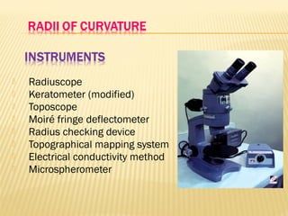
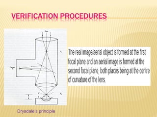
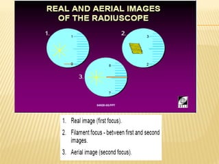
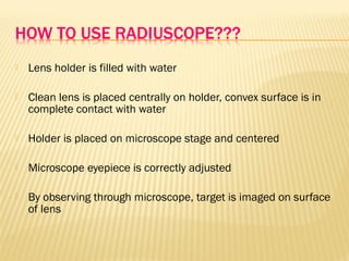
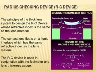
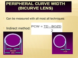
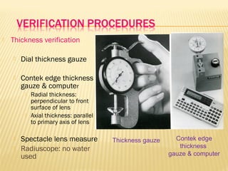
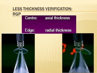
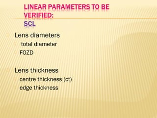
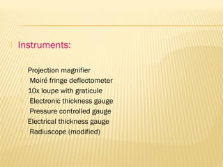
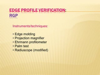
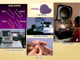


This document discusses the verification process for contact lenses. It has two main stages - laboratory and clinical. In the laboratory, lenses are checked to ensure their parameters match what was ordered. Clinically, lenses should be verified upon receipt to ensure the correct lens was dispensed. Parameters like radius of curvature, diameters, thickness and power must be measured for both rigid and soft contact lenses using various techniques and instruments. On-eye verification is also important to assess fit and comfort. The goal of verification is to ensure patients receive high quality lenses that meet specifications and provide good vision.

![Types of pediatric contact lens [autosaved]](https://cdn.slidesharecdn.com/ss_thumbnails/typesofpediatriccontactlensautosaved-200210123904-thumbnail.jpg?width=640&height=640&fit=bounds)

![Optics of contact lens and nomenclature copy [repaired] (1)](https://cdn.slidesharecdn.com/ss_thumbnails/opticsofcontactlensandnomenclature-copyrepaired1-170218054900-thumbnail.jpg?width=640&height=640&fit=bounds)


![PERI-PROSTHETIC FRACTURE NAIL-PLATE CONSTRUCT [NPC].pptx](https://cdn.slidesharecdn.com/ss_thumbnails/drarunkumardrmohamedashrafperiprostheticfrasturenail-plateconstructnpc-260209164459-7e9d15a1-thumbnail.jpg?width=640&height=640&fit=bounds)


