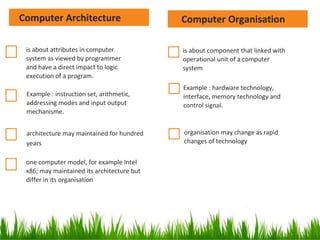
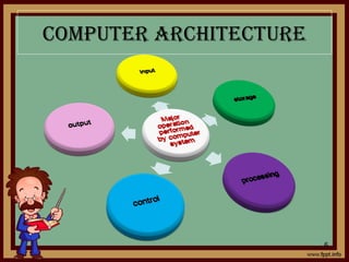
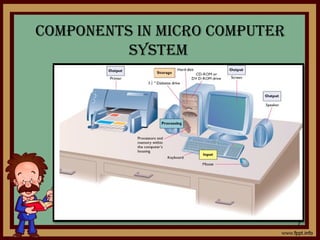
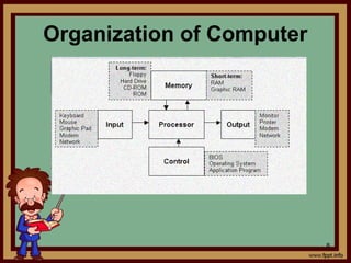
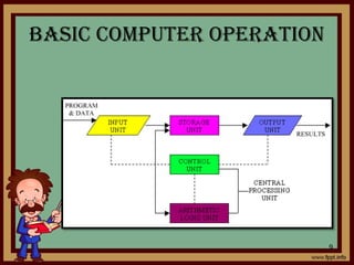
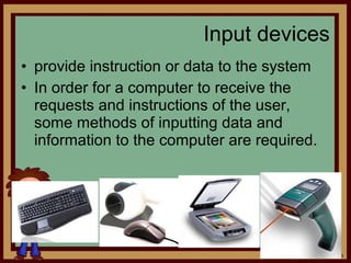
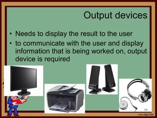
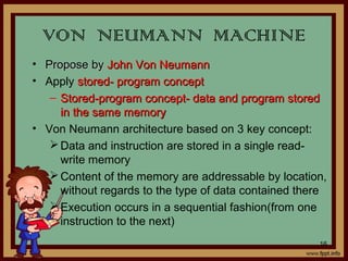
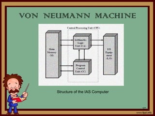
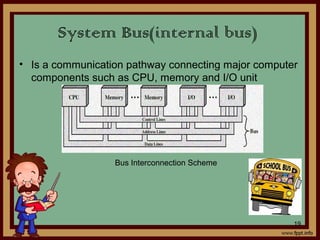
CHAPTER 1
THE COMPUTER
SYSTEM
1
WHAT IS COMPUTER??????
A computer is a device that accepts
information (in the form of digitalized
data) and manipulates it for some result
based on a program or sequence of
instructions on how the data is to be
processed.
2
COMPUTER ARCHITECTURE
• Concerned with the way the hardware
components operate and the way they are
connected together to form the computer
system.
• The various components are assumed to be in
the place and the task is to investigate the
organizational structure to verify that the
computer parts operate as intended.
COMPUTER ORGANISATION
4
• Concern the way hardware components operate and
the way they are connected together to form the
computer system.
• Concerned with the structure and behavior of the
computer as seen by the user. It includes the
information format, the instruction set and techniques
for addressing memory.
• The architectural design of a computer system is
concerned with the specifications of the various
functional modules, such as processors and
memories and structuring them together into a
computer system.
3
is about component that linked with
operational unit of a computer
system
Example : hardware technology,
interface, memory technology and
control signal.
organisation may change as rapid
changes of technology
is about attributes in computer
system as viewed by programmer
and have a direct impact to logic
execution of a program.
Example : instruction set, arithmetic,
addressing modes and input output
mechanisme.
architecture may maintained for hundred
years
one computer model, for example Intel
x86; may maintained its architecture but
differ in its organisation
Computer OrganisationComputer Architecture
COMPUTER ARChITECTURE
6
COMPONENTS IN MICRO COMPUTER
SySTEM
7
Organization of Computer
8
BASIC COMPUTER OPERATION
9
• provide instruction or data to the system
• In order for a computer to receive the
requests and instructions of the user,
some methods of inputting data and
information to the computer are required.
Input devices
10
• Needs to display the result to the user
• to communicate with the user and display
information that is being worked on, output
device is required
Output devices
11
Memory/main memory
• Used to store instruction or data
• Operation on data requires access for more than one
time, so data and instruction have to be stored
temporarily
External storage
• backing store or secondary memory, allows the
permanent storage of large quantities of data
storage
12
• the central brain of the PC
• Referred as central processing unit(CPU)
• majority of the operations of the computer
are handled by the processor
• contains ALU, registers and control unit
processing
13
control
Control the processing of instructions and
the movement of data from one part of the
CPU to another
14
• Arithmetic and Logic Unit (ALU)
- where arithmetic and Boolean logical calculations
are performed (arithmetic, logic and comparison)
• Control Unit
- controls the flow of information through the
processor, and coordinates the activities of the
other units within it
• Central Processing Unit(CPU)
- brain of any computer system
- execute programs stored in the main memory by
fetching, examining and executing instruction one
after another
How ALU,CU and CPU control the
operation of computer????
15
Basic
computer
functional
unit
• Propose byPropose by John Von NeumannJohn Von Neumann
• Apply stored- program conceptstored- program concept
– Stored-program concept- data and program storedStored-program concept- data and program stored
in the same memoryin the same memory
• Von Neumann architecture based on 3 key concept:
Data and instruction are stored in a single read-
write memory
Content of the memory are addressable by location,
without regards to the type of data contained there
Execution occurs in a sequential fashion(from one
instruction to the next)
VON NEUMANN MACHINE
16
VON NEUMANN MACHINE
Structure of the IAS Computer
17
VON NEUMANN MACHINE
 It consists of
A main memorymain memory which stores both data
and instruction
An arithmetic and logic unit(ALU)arithmetic and logic unit(ALU) capable
of operating on binary data
A control unitcontrol unit, which interprets the
instruction in memory and causes them to
be executed
Input output(I/O)Input output(I/O) equipment operated by
control unit
18
• Is a communication pathway connecting major computer
components such as CPU, memory and I/O unit
System Bus(internal bus)
Bus Interconnection Scheme
19
• A data bus simply carries data.
• Internal buses carry information within the
processor, while
• External buses carry data between the
processor and the memory.
• Typically, the same data bus is used for
both read/write operations.
DATA BUS/LINES
20
• A path for moving data between system
modules
• Data bus consist of 32 to hundreds lines,
lines referred as width of data bus
• Width of data bus determine the overall
system’s performance
DATA BUS/LINES
21
• Used to indicate the source or destination of
data on the data bus
• e.g. CPU needs to read a word of data from
memory, it puts the address of desired word on
the address line
 Bus width determines maximum memory
capacity of system(number of address locations
that can be accessed)
ADDRESS BUS
22
• Microprocessor uses control bus to
process data, that is what to do with the
selected memory location.
• Some control signals are Read, Write and
Opcode fetch etc.
CONTROL BUS/LINES
23
• Control the access and the uses of data
and address line. Provide timing
information
– Memory read/write signal
– Interrupt request
– Clock signals
CONTROL BUS/LINES
24
LOCAL BUS
BUS SPEED COMPARISON
Bus
type
Width
(bits)
Speed
(MHz)
Total Data
Rate (MB/Sec)
ISA
EISA
VL-bus
VL-bus
PCI
PCI
PCIe
16
32
32
32
32
64
Serial
8
8
25
33
33
33
16
32
100
132
132
264
250 per lane
25
Peripheral Bus
(external/expansion bus)
• Electronic pathways that connects the
different external devices, peripherals,
expansion slots, I/O ports and drive
connections to the rest of the computer
• allows various devices to be added to the
computer(computer capacities increased)
• Slower than internal bus
26
Types of external busesTypes of external buses
ISA
 Introduced by IBM, ISA or Industry Standard
Architecture
 originally an 8-bit bus and later expanded to a 16-bit
bus
 still in use because it's cheap and for backwards
compatibility
16bit ISA Card
16bit ISA Slot
27
PCI(Peripheral Component
Interconnect )
Introduced by Intel in 1992
32-bit or 64-bit expansion bus
most popular expansion bus use in today's
computers
PCI Card
PCI Slot
28
USB (Universal Serial Bus)
most popular form of bus use today
USB is hot swappable
USB can daisy chain up to 127 devices
USB Speeds
USB 1.0 supports 1.5Mbps
USB 1.1 supports 12Mbps
USB 2.0 supports up to 480Mbps
USB 3.0 supports up to 4.8Gbps
USB A
Connector
USB B Connector
29
AGP (Advanced Graphic Port)
Introduced by Intel in 1997
32-bit bus or 64-bit bus designed for the high
demands of 3-D graphics
has a direct line to the computers memory
which allows 3-D elements to be stored in the
system memory instead of the video memory
fastest expansion bus in use but its only for
video or graphics environment
AGP Card
AGP Slot
30
Cache MemoryCache Memory
31
Cache MemoryCache Memory
Cache memory, is a fast RAM system designed to
hold data recently accessed from the disk drive that
the microprocessor may need again.
The cache contains a copy portion of the main
memory
When the processor attempts to read a word of
memory , a check is made to determine if the word
is in cache. If so the word is delivered to processor.
If not a block of main memory is read into cache
and the required word is transferred to processor
32
Cache MemoryCache Memory
33
Cache and Main Memory
Address/ cache mappingAddress/ cache mapping
34
- Is the way to map/place main memory blocks
into cache slots
Commonly used methods:
 Associative Mapped Cache
 Direct-Mapped Cache
 Set-Associative Mapped Cache
Address mappingAddress mapping
35
Associative Direct
Set-Associative
Address mappingAddress mapping
36
Direct
- Simplest technique
- maps each block of the main memory
into one possible cache line
37
Address mappingAddress mapping
38
Associative
- No restriction on mapping from M to C.”
Associative search of tags is expensive.
Feasible for very small size caches only.
- overcome the disadvantages of the
direct mapped by permitting each main
memory block to be loaded into any line
of cache
39
Address mappingAddress mapping
40
Set Associative
- combines the strengths of both direct
and associative approaching
41
Input /Output in computerInput /Output in computer
systemsystem
an element of computer system
composed of two parts
oInput unit-providing input to processor
oOutput unit-receiving output from processor
Provide interaction with outside world
42
Block diagram i/o unitBlock diagram i/o unit
43
Input and Output DevicesInput and Output Devices
Input devices
-human data entry devices and source entry devices
-human entry devices(keyboard, mouse, joystick, digitizing
tablet,..)
-source entry devices(microphone, soundcard, video camera,…)
Output devices
-hardcopy and softcopy devices
-hardcopy devices(printer, plotter)
-softcopy devices(monitor, visual display terminal, video output,…)
44
Input/output module(interface)Input/output module(interface)
 Provides a method for transferring information between internal
storage (such as memory and CPU registers) and external I/O
devices
 Resolves the differences between the computer and peripheral
devices
1) Peripherals - Electromechanical Devices
CPU or Memory - Electronic Device
2) Data Transfer Rate
»Peripherals - Usually slower
»CPU or Memory - Usually faster than peripherals
3) Unit of Information
»Peripherals – Byte, Block, …
»CPU or Memory – Word
So, some kinds of Synchronization mechanism may be needed
45
Input/output modulediagramInput/output modulediagram
46
Input/output ModuleInput/output Module
Major function:-
Control and timing
Processor communication
Device communication
Data buffering
Error detection
47
Generic Model of I/O ModuleGeneric Model of I/O Module
48
I/O StepsI/O Steps
•CPU checks I/O module device status
•I/O module returns status
•If ready, CPU requests data transfer
•I/O module gets data from device
•I/O module transfers data to CPU
49
Input Output TechniquesInput Output Techniques
•Programmed
•Interrupt driven
•Direct Memory Access (DMA)
50
Programmed I/OProgrammed I/O
•CPU has direct control over I/O
–Sensing status
–Read/write commands
–Transferring data
•CPU waits for I/O module to complete
operation
•Waste the CPU time
51
Programmed I/OProgrammed I/O
*i/o will not alert or
interrupt the CPU
52
Interrupt-Driven I/OInterrupt-Driven I/O
able to overcome programmed I/O
disadvantages
CPU have to wait for a long time for I/O
module
CPU issue an I/O command to a module and
will go on to do other useful work. I/O will
interrupt the CPU when it is ready for
exchange data. The CPU execute the data
transfer and resume to its former processing.
53
Direct Memory AccessDirect Memory Access
Draw back of programmed and interrupt
driven I/O
I/O transfer rate is limited
Processor is tied up in managing an I/O data transfer.
When dealing with a large volume of
data, more efficient method are
required-DMA
54
Direct Memory Access(DMA)Direct Memory Access(DMA)
•Transfer large amounts of data at high speed without
continuous intervention by the processor
•Special control circuit required in the I/O device
interface, called a DMA controller
•DMA controller keeps track of memory locations,
transfers directly to memory (via the bus)
independent of the processor
55
Direct Memory Access(DMA)Direct Memory Access(DMA)
 when processor wishes to read/write, it send the
command to DMA module by issuing information
as:-
 Direction of transfer,read(I/O memory) or write (memory I/O)
 Address of the I/O device involved
 The starting location of the block of the data in memory
 The size of the block to be transferred
The processor continue with other work. It has
delegated this DMA module.
56
Direct Memory Access(DMA)Direct Memory Access(DMA)
DMA module transfers the entire block of
data, directly from memory without involving
processor.
After completing the data transfer, DMA
modules sends interrupt signal to the
processor.
Processor only involved in beginning and end
of the transfer
57
ADVANTAGESOF USINGADVANTAGESOF USING
DMADMA
◦ DMA can reduce the CPU waiting time of
both IO operations.
◦ DMA allows a peripheral device to read
from/write to memory without going through
the CPU
◦ DMA allows for faster processing since the
processor can be working on something else
while the peripheral can be populating
memory.
58
59
Serial AND PARALLELSerial AND PARALLEL
CommunicationCommunication
 Serial communication is the process of sending
data one bit at a time, sequentially, over a
communication channel or computer bus.
  Parallel communication, where several bits are
sent as a whole, on a link with several parallel
channels.
60
61
AsynchronouscommunicationAsynchronouscommunication
Data is transmitted one byte at one time
High amount of overhead(effect on the
computer’s performance)
62
SynchronousSynchronous
All communication can happen at the same
time
Data is transmitted as frames of large data
blocks rather than a bulky individual bytes
More efficient method and costly compared to
asynchronous
63
64

POLITEKNIK MALAYSIA

  • 1.
  • 2.
    WHAT IS COMPUTER?????? Acomputer is a device that accepts information (in the form of digitalized data) and manipulates it for some result based on a program or sequence of instructions on how the data is to be processed. 2
  • 3.
    COMPUTER ARCHITECTURE • Concernedwith the way the hardware components operate and the way they are connected together to form the computer system. • The various components are assumed to be in the place and the task is to investigate the organizational structure to verify that the computer parts operate as intended.
  • 4.
    COMPUTER ORGANISATION 4 • Concernthe way hardware components operate and the way they are connected together to form the computer system. • Concerned with the structure and behavior of the computer as seen by the user. It includes the information format, the instruction set and techniques for addressing memory. • The architectural design of a computer system is concerned with the specifications of the various functional modules, such as processors and memories and structuring them together into a computer system.
  • 5.
    3 is about componentthat linked with operational unit of a computer system Example : hardware technology, interface, memory technology and control signal. organisation may change as rapid changes of technology is about attributes in computer system as viewed by programmer and have a direct impact to logic execution of a program. Example : instruction set, arithmetic, addressing modes and input output mechanisme. architecture may maintained for hundred years one computer model, for example Intel x86; may maintained its architecture but differ in its organisation Computer OrganisationComputer Architecture
  • 6.
  • 7.
    COMPONENTS IN MICROCOMPUTER SySTEM 7
  • 8.
  • 9.
  • 10.
    • provide instructionor data to the system • In order for a computer to receive the requests and instructions of the user, some methods of inputting data and information to the computer are required. Input devices 10
  • 11.
    • Needs todisplay the result to the user • to communicate with the user and display information that is being worked on, output device is required Output devices 11
  • 12.
    Memory/main memory • Usedto store instruction or data • Operation on data requires access for more than one time, so data and instruction have to be stored temporarily External storage • backing store or secondary memory, allows the permanent storage of large quantities of data storage 12
  • 13.
    • the centralbrain of the PC • Referred as central processing unit(CPU) • majority of the operations of the computer are handled by the processor • contains ALU, registers and control unit processing 13
  • 14.
    control Control the processingof instructions and the movement of data from one part of the CPU to another 14
  • 15.
    • Arithmetic andLogic Unit (ALU) - where arithmetic and Boolean logical calculations are performed (arithmetic, logic and comparison) • Control Unit - controls the flow of information through the processor, and coordinates the activities of the other units within it • Central Processing Unit(CPU) - brain of any computer system - execute programs stored in the main memory by fetching, examining and executing instruction one after another How ALU,CU and CPU control the operation of computer???? 15 Basic computer functional unit
  • 16.
    • Propose byProposeby John Von NeumannJohn Von Neumann • Apply stored- program conceptstored- program concept – Stored-program concept- data and program storedStored-program concept- data and program stored in the same memoryin the same memory • Von Neumann architecture based on 3 key concept: Data and instruction are stored in a single read- write memory Content of the memory are addressable by location, without regards to the type of data contained there Execution occurs in a sequential fashion(from one instruction to the next) VON NEUMANN MACHINE 16
  • 17.
    VON NEUMANN MACHINE Structureof the IAS Computer 17
  • 18.
    VON NEUMANN MACHINE It consists of A main memorymain memory which stores both data and instruction An arithmetic and logic unit(ALU)arithmetic and logic unit(ALU) capable of operating on binary data A control unitcontrol unit, which interprets the instruction in memory and causes them to be executed Input output(I/O)Input output(I/O) equipment operated by control unit 18
  • 19.
    • Is acommunication pathway connecting major computer components such as CPU, memory and I/O unit System Bus(internal bus) Bus Interconnection Scheme 19
  • 20.
    • A databus simply carries data. • Internal buses carry information within the processor, while • External buses carry data between the processor and the memory. • Typically, the same data bus is used for both read/write operations. DATA BUS/LINES 20
  • 21.
    • A pathfor moving data between system modules • Data bus consist of 32 to hundreds lines, lines referred as width of data bus • Width of data bus determine the overall system’s performance DATA BUS/LINES 21
  • 22.
    • Used toindicate the source or destination of data on the data bus • e.g. CPU needs to read a word of data from memory, it puts the address of desired word on the address line  Bus width determines maximum memory capacity of system(number of address locations that can be accessed) ADDRESS BUS 22
  • 23.
    • Microprocessor usescontrol bus to process data, that is what to do with the selected memory location. • Some control signals are Read, Write and Opcode fetch etc. CONTROL BUS/LINES 23
  • 24.
    • Control theaccess and the uses of data and address line. Provide timing information – Memory read/write signal – Interrupt request – Clock signals CONTROL BUS/LINES 24
  • 25.
    LOCAL BUS BUS SPEEDCOMPARISON Bus type Width (bits) Speed (MHz) Total Data Rate (MB/Sec) ISA EISA VL-bus VL-bus PCI PCI PCIe 16 32 32 32 32 64 Serial 8 8 25 33 33 33 16 32 100 132 132 264 250 per lane 25
  • 26.
    Peripheral Bus (external/expansion bus) •Electronic pathways that connects the different external devices, peripherals, expansion slots, I/O ports and drive connections to the rest of the computer • allows various devices to be added to the computer(computer capacities increased) • Slower than internal bus 26
  • 27.
    Types of externalbusesTypes of external buses ISA  Introduced by IBM, ISA or Industry Standard Architecture  originally an 8-bit bus and later expanded to a 16-bit bus  still in use because it's cheap and for backwards compatibility 16bit ISA Card 16bit ISA Slot 27
  • 28.
    PCI(Peripheral Component Interconnect ) Introducedby Intel in 1992 32-bit or 64-bit expansion bus most popular expansion bus use in today's computers PCI Card PCI Slot 28
  • 29.
    USB (Universal SerialBus) most popular form of bus use today USB is hot swappable USB can daisy chain up to 127 devices USB Speeds USB 1.0 supports 1.5Mbps USB 1.1 supports 12Mbps USB 2.0 supports up to 480Mbps USB 3.0 supports up to 4.8Gbps USB A Connector USB B Connector 29
  • 30.
    AGP (Advanced GraphicPort) Introduced by Intel in 1997 32-bit bus or 64-bit bus designed for the high demands of 3-D graphics has a direct line to the computers memory which allows 3-D elements to be stored in the system memory instead of the video memory fastest expansion bus in use but its only for video or graphics environment AGP Card AGP Slot 30
  • 31.
  • 32.
    Cache MemoryCache Memory Cachememory, is a fast RAM system designed to hold data recently accessed from the disk drive that the microprocessor may need again. The cache contains a copy portion of the main memory When the processor attempts to read a word of memory , a check is made to determine if the word is in cache. If so the word is delivered to processor. If not a block of main memory is read into cache and the required word is transferred to processor 32
  • 33.
  • 34.
    Address/ cache mappingAddress/cache mapping 34 - Is the way to map/place main memory blocks into cache slots Commonly used methods:  Associative Mapped Cache  Direct-Mapped Cache  Set-Associative Mapped Cache
  • 35.
  • 36.
    Address mappingAddress mapping 36 Direct -Simplest technique - maps each block of the main memory into one possible cache line
  • 37.
  • 38.
    Address mappingAddress mapping 38 Associative -No restriction on mapping from M to C.” Associative search of tags is expensive. Feasible for very small size caches only. - overcome the disadvantages of the direct mapped by permitting each main memory block to be loaded into any line of cache
  • 39.
  • 40.
    Address mappingAddress mapping 40 SetAssociative - combines the strengths of both direct and associative approaching
  • 41.
  • 42.
    Input /Output incomputerInput /Output in computer systemsystem an element of computer system composed of two parts oInput unit-providing input to processor oOutput unit-receiving output from processor Provide interaction with outside world 42
  • 43.
    Block diagram i/ounitBlock diagram i/o unit 43
  • 44.
    Input and OutputDevicesInput and Output Devices Input devices -human data entry devices and source entry devices -human entry devices(keyboard, mouse, joystick, digitizing tablet,..) -source entry devices(microphone, soundcard, video camera,…) Output devices -hardcopy and softcopy devices -hardcopy devices(printer, plotter) -softcopy devices(monitor, visual display terminal, video output,…) 44
  • 45.
    Input/output module(interface)Input/output module(interface) Provides a method for transferring information between internal storage (such as memory and CPU registers) and external I/O devices  Resolves the differences between the computer and peripheral devices 1) Peripherals - Electromechanical Devices CPU or Memory - Electronic Device 2) Data Transfer Rate »Peripherals - Usually slower »CPU or Memory - Usually faster than peripherals 3) Unit of Information »Peripherals – Byte, Block, … »CPU or Memory – Word So, some kinds of Synchronization mechanism may be needed 45
  • 46.
  • 47.
    Input/output ModuleInput/output Module Majorfunction:- Control and timing Processor communication Device communication Data buffering Error detection 47
  • 48.
    Generic Model ofI/O ModuleGeneric Model of I/O Module 48
  • 49.
    I/O StepsI/O Steps •CPUchecks I/O module device status •I/O module returns status •If ready, CPU requests data transfer •I/O module gets data from device •I/O module transfers data to CPU 49
  • 50.
    Input Output TechniquesInputOutput Techniques •Programmed •Interrupt driven •Direct Memory Access (DMA) 50
  • 51.
    Programmed I/OProgrammed I/O •CPUhas direct control over I/O –Sensing status –Read/write commands –Transferring data •CPU waits for I/O module to complete operation •Waste the CPU time 51
  • 52.
    Programmed I/OProgrammed I/O *i/owill not alert or interrupt the CPU 52
  • 53.
    Interrupt-Driven I/OInterrupt-Driven I/O ableto overcome programmed I/O disadvantages CPU have to wait for a long time for I/O module CPU issue an I/O command to a module and will go on to do other useful work. I/O will interrupt the CPU when it is ready for exchange data. The CPU execute the data transfer and resume to its former processing. 53
  • 54.
    Direct Memory AccessDirectMemory Access Draw back of programmed and interrupt driven I/O I/O transfer rate is limited Processor is tied up in managing an I/O data transfer. When dealing with a large volume of data, more efficient method are required-DMA 54
  • 55.
    Direct Memory Access(DMA)DirectMemory Access(DMA) •Transfer large amounts of data at high speed without continuous intervention by the processor •Special control circuit required in the I/O device interface, called a DMA controller •DMA controller keeps track of memory locations, transfers directly to memory (via the bus) independent of the processor 55
  • 56.
    Direct Memory Access(DMA)DirectMemory Access(DMA)  when processor wishes to read/write, it send the command to DMA module by issuing information as:-  Direction of transfer,read(I/O memory) or write (memory I/O)  Address of the I/O device involved  The starting location of the block of the data in memory  The size of the block to be transferred The processor continue with other work. It has delegated this DMA module. 56
  • 57.
    Direct Memory Access(DMA)DirectMemory Access(DMA) DMA module transfers the entire block of data, directly from memory without involving processor. After completing the data transfer, DMA modules sends interrupt signal to the processor. Processor only involved in beginning and end of the transfer 57
  • 58.
    ADVANTAGESOF USINGADVANTAGESOF USING DMADMA ◦DMA can reduce the CPU waiting time of both IO operations. ◦ DMA allows a peripheral device to read from/write to memory without going through the CPU ◦ DMA allows for faster processing since the processor can be working on something else while the peripheral can be populating memory. 58
  • 59.
  • 60.
    Serial AND PARALLELSerialAND PARALLEL CommunicationCommunication  Serial communication is the process of sending data one bit at a time, sequentially, over a communication channel or computer bus.   Parallel communication, where several bits are sent as a whole, on a link with several parallel channels. 60
  • 61.
  • 62.
    AsynchronouscommunicationAsynchronouscommunication Data is transmittedone byte at one time High amount of overhead(effect on the computer’s performance) 62
  • 63.
    SynchronousSynchronous All communication canhappen at the same time Data is transmitted as frames of large data blocks rather than a bulky individual bytes More efficient method and costly compared to asynchronous 63
  • 64.