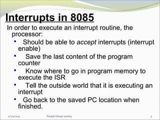
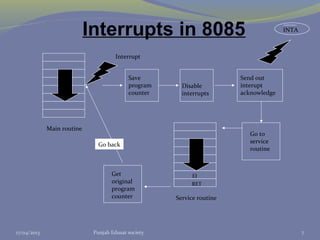
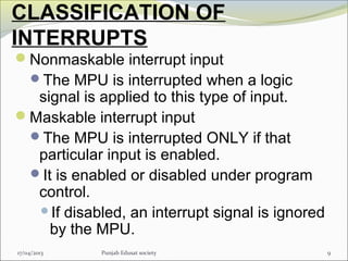
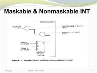
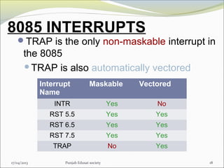
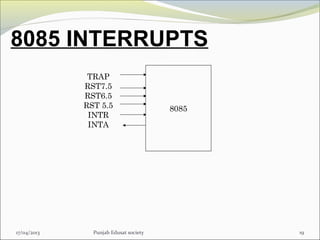
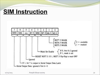
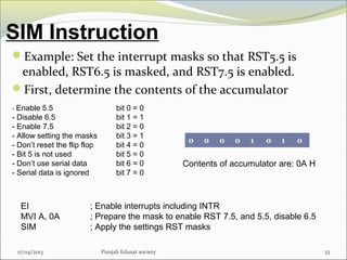
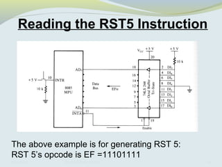
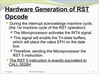
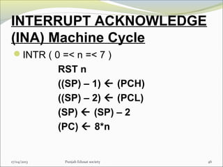
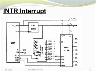
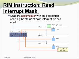
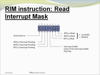
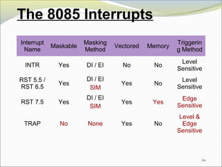
The document discusses interrupts in the 8085 microprocessor. It describes how interrupts work, including how the 8085 handles different types of interrupts like maskable, non-maskable, vectored and non-vectored interrupts. It provides details on the interrupt handling process, interrupt priorities, the interrupt mask and how individual interrupts can be enabled or disabled.
2. INTRODUCTION
Interrupt is a process where an external
device can get the attention of the
microprocessor.
The process starts from the I/O device
The process is asynchronous.
An interrupt is considered to be an
emergency signal that may be serviced.
The Microprocessor may respond to it
as soon as possible.
217/04/2013 Punjab Edusat society
3. INTRODUCTION
What happens when MP is interrupted ?
When the Microprocessor receives an
interrupt signal, it suspends the currently
executing program and jumps to an
Interrupt Service Routine (ISR) to
respond to the incoming interrupt.
Each interrupt will most probably have
its own ISR.
317/04/2013 Punjab Edusat society
4. Interrupts in 8085
When the interrupt signal arrives:
The processor will break its routine
Go to a different routine (interrupt
service routine)
Complete the interrupt service
routine(ISR)
Go back to the “regular” routine
17/04/2013 Punjab Edusat society 4
5. Interrupts in 8085
In order to execute an interrupt routine, the
processor:
Should be able to accept interrupts (interrupt
enable)
Save the last content of the program
counter
Know where to go in program memory to
execute the ISR
Tell the outside world that it is executing an
interrupt
Go back to the saved PC location when
finished.
17/04/2013 Punjab Edusat society 5
6. Interrupts in 8085
Interrupts increase processor system
efficiency by letting I/O device request CPU
time only when that device needs immediate
attention.
An interrupt is a subroutine call initialized by
external hardware.
The request is asynchronous it may
occur at any point in a program’s execution.
17/04/2013 Punjab Edusat society 6
7. 7
Interrupts in 8085
Main routine
Interrupt
Save
program
counter
Disable
interrupts
Send out
interupt
acknowledge
Service routine
INTA
Go to
service
routine
Get
original
program
counter
Go back
EI
RET
17/04/2013 Punjab Edusat society
8. CLASSIFICATION OF
INTERRUPTS
• Interrupts can be classified into two types:
Maskable Interrupts (Can be delayed or
Rejected)
Non-Maskable Interrupts (Can not be
delayed or Rejected)
• Interrupts can also be classified into:
Vectored (the address of the service
routine is hard-wired)
Non-vectored (the address of the
service routine needs to be supplied
externally by the device)
817/04/2013 Punjab Edusat society
9. CLASSIFICATION OF
INTERRUPTS
Nonmaskable interrupt input
The MPU is interrupted when a logic
signal is applied to this type of input.
Maskable interrupt input
The MPU is interrupted ONLY if that
particular input is enabled.
It is enabled or disabled under program
control.
If disabled, an interrupt signal is ignored
by the MPU.
917/04/2013 Punjab Edusat society
11. Response to Interrupt
Responding to an interrupt may be
immediate or delayed depending on
whether the interrupt is maskable or non-
maskable and whether interrupts are being
masked or not.
MP completes its current machine cycle.
17/04/2013 Punjab Edusat society 11
12. Response to Interrupt
There are two ways of redirecting the
execution to the ISR depending on
whether the interrupt is vectored or non-
vectored.
Vectored: The address of the subroutine
is already known to the Microprocessor
Non Vectored: The device will have to
supply the address of the subroutine to
the Microprocessor
17/04/2013 Punjab Edusat society 12
13. Response to Interrupt
17/04/2013 Punjab Edusat society 13
1. The processing of the current instruction is
completed.
2. An interrupt machine cycle is executed
during which the PC is saved and control is
transferred to an appropriate memory
location.
3. The state of the MPU is saved.
4. If more than one I/O device is associated
with the location transferred to, the highest
priority device requesting an interrupt is
identified.
14. Response to Interrupt
5. A subroutine is executed which services
the interrupt I/O device.
6. The saved state of the microprocessor is
restored.
7. Control is returned to the instruction that
follows the interrupted instruction.
17/04/2013 Punjab Edusat society 14
15. 8085 INTERRUPT STRUCTURE
17/04/2013 Punjab Edusat society 15
There are 5 interrupt inputs:
TRAP (nonmaskable)
RST7.5
RST6.5
RST5.5
INTR
16. 8085 INTERRUPTS
The ‘EI’ instruction is a one byte
instruction and is used to Enable the
maskable interrupts.
The ‘DI’ instruction is a one byte
instruction and is used to Disable the
maskable interrupts.
The 8085 has a single Non-Maskable
interrupt.
17/04/2013 Punjab Edusat society 16
17. 8085 INTERRUPTS
The 8085 has 5 interrupt inputs.
The INTR input.
The INTR input is the only non-vectored
interrupt.
INTR is maskable using the EI/DI
instruction pair.
RST 5.5, RST 6.5, RST 7.5 are all
automatically vectored.
RST 5.5, RST 6.5, and RST 7.5 are all
maskable.
17/04/2013 Punjab Edusat society 17
18. 8085 INTERRUPTS
TRAP is the only non-maskable interrupt in
the 8085
TRAP is also automatically vectored
17/04/2013 Punjab Edusat society 18
Interrupt
Name
Maskable Vectored
INTR Yes No
RST 5.5 Yes Yes
RST 6.5 Yes Yes
RST 7.5 Yes Yes
TRAP No Yes
20. Vectored Interrupts
17/04/2013 Punjab Edusat society 20
An interrupt vector is a pointer to where the
ISR is stored in memory.
All interrupts (vectored or otherwise) are
mapped onto a memory area called the
Interrupt Vector Table (IVT).
The IVT is usually located in memory page
00 (0000H - 00FFH).
21. Vectored Interrupts
17/04/2013 Punjab Edusat society 21
There are four interrupt inputs in 8085 that
transfer the operation immediately to a
specific address:
TRAP : go to 0024
RST 7.5: go to 003C
RST 6.5 0034
RST 5.5 002C
RST 7.5, RST 6.5 and RST 5.5 are
maskable interrupts, they are
acknowledged only if they are not
masked !
22. Vectored Interrupts
17/04/2013 Punjab Edusat society 22
•Finding the address of these vectored
interrupts are very easy .Just multiply 8 with
the RST value i.e for RST 7.5 the
subroutine(ISR) address=8*7.5=60=(3c)H.
•For TRAP ,its RST value is 4.5,then the
subroutine address is 8*4.5=36=(24)H.
similarly u can calculate for other vector
interupt addresses.
•Memory page for all interrupts are (00).
24. Masking RST 5.5, RST 6.5 and RST 7.5
17/04/2013 Punjab Edusat society 24
These three interrupts are masked at two
levels:
Through the Interrupt Enable flip flop and
the EI/DI instructions.
The Interrupt Enable flip flop controls the
whole maskable interrupt process.
Through individual mask flip flops that
control the availability of the individual
interrupts.
These flip flops control the interrupts
individually.
26. Maskable/Vectored Interrupt
Process
1. The interrupt process should be enabled
using the EI instruction.
2. The 8085 checks for an interrupt during
the execution of every instruction.
3. If there is an interrupt, and if the interrupt
is enabled using the interrupt mask, the
microprocessor will complete the
executing instruction, and reset the
interrupt flip flop.
17/04/2013 Punjab Edusat society 26
27. Maskable/Vectored Interrupt
Process
4. The microprocessor then executes a call
instruction that sends the execution to the
appropriate location in the interrupt vector
table.
5. When the microprocessor executes the
call instruction, it saves the address of
the next instruction on the stack.
6. The microprocessor jumps to the specific
service routine.
17/04/2013 Punjab Edusat society 27
28. Maskable/Vectored Interrupt
Process
7. The service routine must include the
instruction EI to re-enable the interrupt
process.
8. At the end of the service routine, the RET
instruction returns the execution to where
the program was interrupted.
17/04/2013 Punjab Edusat society 28
29. Maskable/Vectored Interrupt
Process
The Interrupt Enable flip flop is
manipulated using the EI/DI instructions.
The individual masks for RST 5.5, RST
6.5 and RST 7.5 are manipulated using the
SIM instruction (Set Interrupt Mask).
This instruction takes the bit pattern in the
Accumulator and applies it to the interrupt
mask enabling and disabling the specific
interrupts.
17/04/2013 Punjab Edusat society 29
31. SIM Instruction
17/04/2013 Punjab Edusat society 31
Bit 0 is the mask for RST 5.5, bit 1 is the
mask for RST 6.5 and bit 2 is the mask for
RST 7.5.
If the mask bit is 0, the interrupt is
available.
If the mask bit is 1, the interrupt is
masked.
Bit 3 (Mask Set Enable - MSE) is an enable
for setting the mask.
If it is set to 0 the mask is ignored and the
old settings remain.
If it is set to 1, the new setting are
applied.
32. SIM Instruction
17/04/2013 Punjab Edusat society 32
Bit 4 of the accumulator in the SIM
instruction allows explicitly resetting the RST
7.5 memory even if the microprocessor did
not respond to it.
Bit 5 is not used by the SIM instruction
Bit 6 & Bit 7 is used for extra functionality
such as serial data transmission.
33. SIM Instruction
17/04/2013 Punjab Edusat society 33
Example: Set the interrupt masks so that RST5.5 is
enabled, RST6.5 is masked, and RST7.5 is enabled.
First, determine the contents of the accumulator
- Enable 5.5 bit 0 = 0
- Disable 6.5 bit 1 = 1
- Enable 7.5 bit 2 = 0
- Allow setting the masks bit 3 = 1
- Don’t reset the flip flop bit 4 = 0
- Bit 5 is not used bit 5 = 0
- Don’t use serial data bit 6 = 0
- Serial data is ignored bit 7 = 0
0 0 0 0 1 0 1 0
Contents of accumulator are: 0A H
EI ; Enable interrupts including INTR
MVI A, 0A ; Prepare the mask to enable RST 7.5, and 5.5, disable 6.5
SIM ; Apply the settings RST masks
34. Triggering Levels:
RST 7.5 is positive edge sensitive.
When a positive edge appears on the
RST7.5 line, a logic 1 is stored in the flip-flop
as a “pending” interrupt.
Since the value has been stored in the flip
flop, the line does not have to be high when
the microprocessor checks for the interrupt
to be recognized.
The line must go to zero and back to one
before a new interrupt is recognized.
RST 6.5 and RST 5.5 are level sensitive.
The interrupting signal must remain present
until the microprocessor checks for
interrupts.
17/04/2013 Punjab Edusat society 34
35. 17/04/2013 Punjab Edusat society 35
•TRAP is the only non-maskable interrupt.
•It does not need to be enabled because it
cannot be disabled.
•It has the highest priority amongst interrupts.
•It is edge and level sensitive.
•Must make a low-to-high transition and
remain high to be acknowledged.
•After acknowledgement, it is NOT
recognized again until it goes low, then
high again and remains high.
36. 17/04/2013 Punjab Edusat society 36
•It is to avoid false triggering due to noise/logic
glitches.
•TRAP is usually used for power failure and
emergency shutoff.
•When the 8085A is reset:
•Its internal interrupt enable flip-flop is reset.
•This disables ALL the maskable interrupts.
•So, the MPU only responds to TRAP.
•Vectored address for TRAP is 0024 H.
38. 17/04/2013 Punjab Edusat society 38
1. The interrupt process should be enabled
using the EI instruction.
2. The 8085 checks for an interrupt during
the execution of every instruction.
3. If INTR is high, MP completes current
instruction, disables the interrupt and
sends INTA (Interrupt acknowledge) signal
to the device that interrupted .
4. INTA allows the I/O device to send a RST
instruction through data bus.
39. 17/04/2013 Punjab Edusat society 39
5. Upon receiving the INTA signal, MP saves
the memory location of the next instruction
on the stack and the program is
transferred to ‘call’ location (ISR Call)
specified by the RST instruction.
6. Microprocessor Performs the ISR.
7. ISR must include the ‘EI’ instruction to
enable the further interrupt within the
program.
40. 17/04/2013 Punjab Edusat society 40
8. RET instruction at the end of the ISR
allows the MP to retrieve the return
address from the stack and the program
is transferred back to where the program
was interrupted.
9. Although INTR is a maskable interrupt,
it does NOT need SIM to get enabled.
Just instruction EI is enough.
41. Non-Vectored Interrupt
The 8085 recognizes 8 RESTART
instructions: RST0 - RST7.
Each of these would send the execution
to a predetermined hard-wired memory
location:
41
Restart
Instruction
Equivalent
to
RST0 CALL 0000H
RST1 CALL 0008H
RST2 CALL 0010H
RST3 CALL 0018H
RST4 CALL 0020H
RST5 CALL 0028H
RST6 CALL 0030H
RST7 CALL 0038H
17/04/2013 Punjab Edusat society
42. 17/04/2013 Punjab Edusat society 42
•The restart sequence is made up of three
machine cycles
•In the 1st machine cycle:The Microprocessor
sends the INTA signal.
•While INTA is active the microprocessor
reads the data lines expecting to receive,
from the interrupting device, the opcode for
the specific RST instruction.
43. 17/04/2013 Punjab Edusat society 43
•In the 2nd and 3rd machine cycles:the 16-bit
address of the next instruction is saved on
the stack.
•Then the microprocessor jumps to the
address associated with the specified RST
instruction.
•There are 8 different RST instructions.
• Each RST instruction tells the processor to
go to a specific memory address (call
location – fixed)
44. 44
Reading the RST5 Instruction
The above example is for generating RST 5:
RST 5’s opcode is EF =11101111
17/04/2013 Punjab Edusat society
45. Hardware Generation of RST
Opcode
During the interrupt acknowledge machine cycle,
(the 1st machine cycle of the RST operation):
The Microprocessor activates the INTA signal.
This signal will enable the Tri-state buffers,
which will place the value EFH on the data
bus.
Therefore, sending the Microprocessor the
RST 5 instruction.
The RST 5 instruction is exactly equivalent to
CALL 0028H
17/04/2013 Punjab Edusat society 45
47. INTR Interrupt
The microprocessor checks the INTR line
one clock cycle before the last T-state of
each instruction.
The INTR line must be deactivated before
the EI is executed. Otherwise, the
microprocessor will be interrupted again.
Once the microprocessor starts to respond
to an INTR interrupt, INTA becomes active
(=0).Therefore, INTR should be turned off as
soon as the INTA signal is received.
17/04/2013 Punjab Edusat society 47
48. INTR Interrupt
In response to the acknowledge signal,
external logic places an instruction OPCODE
on the data bus. In the case of multibyte
instruction, additional interrupt acknowledge
machine cycles are generated by the 8085 to
transfer the additional bytes into the
microprocessor.
On receiving the instruction, the 8085 save
the address of next instruction on stack and
execute received instruction.
17/04/2013 Punjab Edusat society 48
49. INTR Interrupt
The Programmable Interrupt Controller
(PIC) functions as an overall manager in an
Interrupt-Driven system environment. It
accepts requests from theperipheral
equipment, determines which of the in-
coming requests is of the highest priority.
The 8259A is a device specifically designed
for use in real time, interrupt driven
microcomputer systems.
17/04/2013 Punjab Edusat society 49
50. INTR Interrupt
It manages eight levels or requests and has
built in features for expandability to other
8259A's (up to 64levels). It is programmed
by the system's softwareas an I/O peripheral.
Each peripheral device usually has a special
program or ``routine'' that is associated with
its specific functional or operational
requirements; this is referred to as a
``service routine''.
17/04/2013 Punjab Edusat society 50
51. INTR Interrupt
The PIC,after issuing an Interrupt to the
CPU, must somehowinput information into
the CPU that can ``point'' the Program
Counter to the service routine associated
with the requesting device. This ``pointer'' is
an address in a vectoring table and will often
be referredto, in this document, as vectoring
data.
17/04/2013 Punjab Edusat society 51
53. 17/04/2013 Punjab Edusat society 53
•Since the 8085 has five interrupt lines,
interrupts may occur during an ISR and
remain pending.
•Using the RIM instruction, it is possible to
can read the status of the interrupt lines
and find if there are any pending interrupts.
54. RIM instruction: Read
Interrupt Mask
Load the accumulator with an 8-bit pattern
showing the status of each interrupt pin and
mask.
54
Interrupt Enable
Flip Flop
RST 5.5
RST 6.5
RST 7.5
M 5.5
M 6.5
M 7.5
RST7.5 Memory
SDI
P7.5
P6.5
P5.5
IE
M7.5
M6.5
M5.5
01234567
17/04/2013 Punjab Edusat society
56. 17/04/2013 Punjab Edusat society 56
•Bits 0-2 show the current setting of the
mask for each of RST 7.5, RST 6.5 and
RST 5.5 .They return the contents of the
three mask flip flops.
•Bit 3 shows whether the maskable interrupt
process is enabled or not.
It can be used by a program to
determine whether or not interrupts are
enabled.
57. 17/04/2013 Punjab Edusat society 57
•Bits 4-6 show whether or not there are
pending interrupts on RST 7.5, RST 6.5,
and RST 5.5 .
•Bit 7 is used for Serial Data Input.
The RIM instruction reads the value of
the SID pin on the microprocessor and
returns it in this bit.
58. 17/04/2013 Punjab Edusat society 58
•Microprocessor can be interrupted again
before the completion of the ISR.
•As soon as the 1st interrupt arrives, all
maskable interrupts are disabled.
•They will only be enabled after the execution
of the EI instruction.
•If the EI instruction is placed early in the
ISR, other interrupt may occur before the ISR
is done.
59. 17/04/2013 Punjab Edusat society 59
•There are 8 different RST Instructions .
Multiple interrupts coming from 8 different external
devices
60. 17/04/2013 Punjab Edusat society 60
•How do MPU allow multiple devices to
interrupt using the INTR line?
•The microprocessor can only respond to one
signal on INTR at a time.
•Therefore, we must allow the signal from only
one of the devices to reach the
microprocessor.
•We must assign some priority to the different
devices and allow their signals to reach the
microprocessor according to the priority.
61. 17/04/2013 Punjab Edusat society 61
•The solution is to use a circuit called the
priority encoder as opcodes for the different
RST instructions follow a set pattern.
•By default 8085A have an internally
established, fixed, multilevel priority structure.
•From highest to lowest:
TRAP
RST7.5
RST6.5
RST5.5
INTR
62. The 8085 Interrupts
Interrupt
Name
Maskable
Masking
Method
Vectored Memory
Triggerin
g Method
INTR Yes DI / EI No No
Level
Sensitive
RST 5.5 /
RST 6.5
Yes
DI / EI
SIM
Yes No
Level
Sensitive
RST 7.5 Yes
DI / EI
SIM
Yes Yes
Edge
Sensitive
TRAP No None Yes No
Level &
Edge
Sensitive
62