Downloaded 146 times


![From Conventional to Compressive 3D Displays
mask 2
mask 1
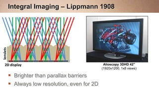
Time-shifted Parallax Barriers [Kim et al. 2007]
High Resolution through High Speed
t
t t
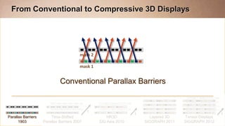
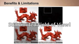
Parallax Barriers Time-Shifted HR3D Layered 3D Tensor Displays
1903 Parallax Barriers 2007 SIG Asia 2010 SIGGRAPH 2011 SIGGRAPH 2012](https://image.slidesharecdn.com/compressivelightfielddisplaysnoclips-121012172928-phpapp01/85/Compressive-Light-Field-Displays-22-320.jpg)
![From Conventional to Compressive 3D Displays
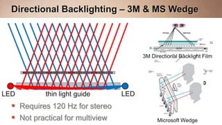
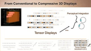
Perceptual Integration
time
Time-shifted Parallax Barriers [Kim et al. 2007]
High Resolution through High Speed
t
t t
Parallax Barriers Time-Shifted HR3D Layered 3D Tensor Displays
1903 Parallax Barriers 2007 SIG Asia 2010 SIGGRAPH 2011 SIGGRAPH 2012](https://image.slidesharecdn.com/compressivelightfielddisplaysnoclips-121012172928-phpapp01/85/Compressive-Light-Field-Displays-23-320.jpg)
![From Conventional to Compressive 3D Displays
mask 2
mask 1
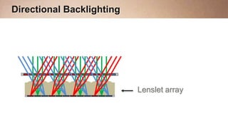
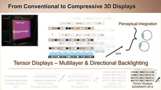
High-Rank 3D [Lanman et al., SIGGRAPH Asia 2010]
Compression in Time – Nonnegative Matrix Factorization
t
t t
Parallax Barriers Time-Shifted HR3D Layered 3D Tensor Displays
1903 Parallax Barriers 2007 SIG Asia 2010 SIGGRAPH 2011 SIGGRAPH 2012](https://image.slidesharecdn.com/compressivelightfielddisplaysnoclips-121012172928-phpapp01/85/Compressive-Light-Field-Displays-24-320.jpg)
![From Conventional to Compressive 3D Displays
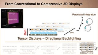
Perceptual Integration
time
High-Rank 3D [Lanman et al., SIGGRAPH Asia 2010]
Compression in Time – Nonnegative Matrix Factorization
t
t t
Parallax Barriers Time-Shifted HR3D Layered 3D Tensor Displays
1903 Parallax Barriers 2007 SIG Asia 2010 SIGGRAPH 2011 SIGGRAPH 2012](https://image.slidesharecdn.com/compressivelightfielddisplaysnoclips-121012172928-phpapp01/85/Compressive-Light-Field-Displays-25-320.jpg)
![From Conventional to Compressive 3D Displays
mask K
…
mask 2
mask 1
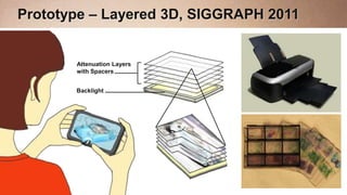
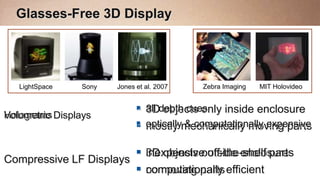
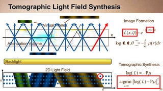
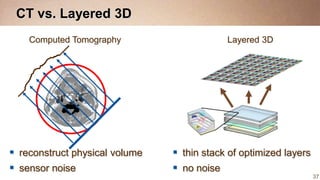
Layered 3D [Wetzstein et al., SIGGRAPH 2011]
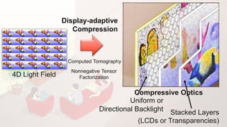
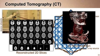
Compression in Pixels & Depth – Computed Tomography
t
t t
Parallax Barriers Time-Shifted HR3D Layered 3D Tensor Displays
1903 Parallax Barriers 2007 SIG Asia 2010 SIGGRAPH 2011 SIGGRAPH 2012](https://image.slidesharecdn.com/compressivelightfielddisplaysnoclips-121012172928-phpapp01/85/Compressive-Light-Field-Displays-26-320.jpg)
![From Conventional to Compressive 3D Displays
mask K
…
mask 2
mask 1
Layered 3D [Wetzstein et al., SIGGRAPH 2011]
Compression in Pixels & Depth – Computed Tomography
t
t t
Parallax Barriers Time-Shifted HR3D Layered 3D Tensor Displays
1903 Parallax Barriers 2007 SIG Asia 2010 SIGGRAPH 2011 SIGGRAPH 2012](https://image.slidesharecdn.com/compressivelightfielddisplaysnoclips-121012172928-phpapp01/85/Compressive-Light-Field-Displays-27-320.jpg)
![From Conventional to Compressive 3D Displays
mask K
…
mask 2
mask 1
Layered 3D [Wetzstein et al., SIGGRAPH 2011]
Compression in Pixels – Computed Tomography
t
t t
Parallax Barriers Time-Shifted HR3D Layered 3D Tensor Displays
1903 Parallax Barriers 2007 SIG Asia 2010 SIGGRAPH 2011 SIGGRAPH 2012](https://image.slidesharecdn.com/compressivelightfielddisplaysnoclips-121012172928-phpapp01/85/Compressive-Light-Field-Displays-28-320.jpg)
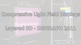


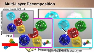
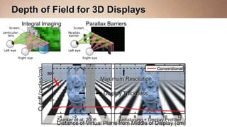
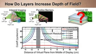
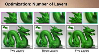
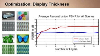
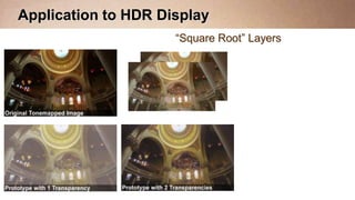

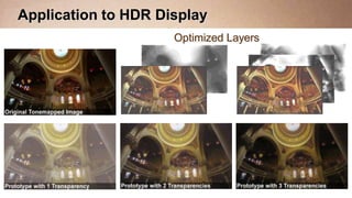

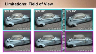
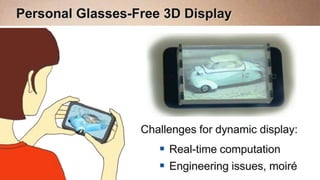
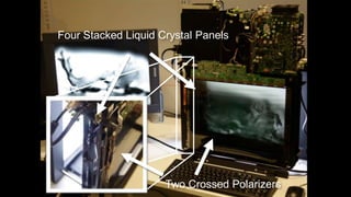
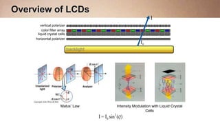
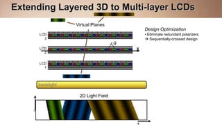
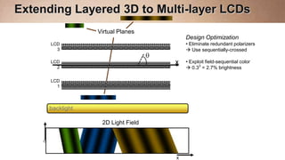
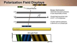
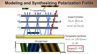
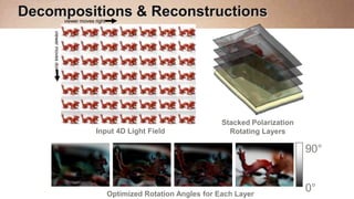
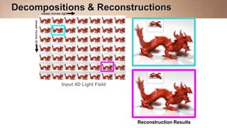
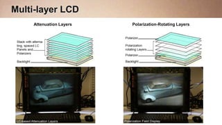

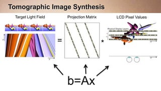
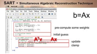

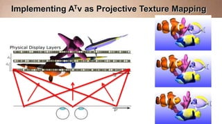
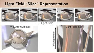
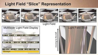
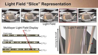
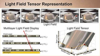
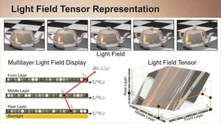
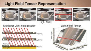
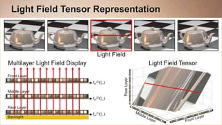
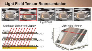
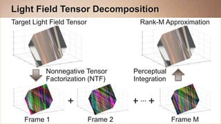

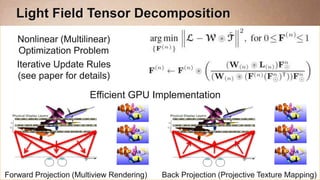

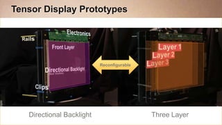
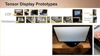


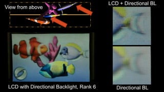


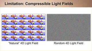
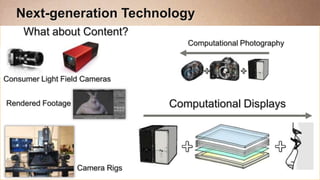
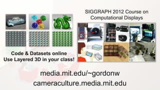

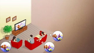
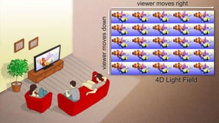
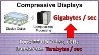
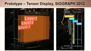
This document summarizes research on compressive light field displays. It begins by introducing the concept of light field displays and their collaborators. It then provides examples of prototypes from layered 3D displays to tensor displays. Finally, it outlines the evolution of display technologies from conventional parallax barriers to the most recent compressive displays that use techniques like nonnegative matrix factorization and computed tomography to achieve compression in time, pixels, and depth for glasses-free 3D viewing.